True TR-30 Operation manual

TRUE RESIDENTIAL®
TR-30
INSTALLATION / USER GUIDE
PRESERVE THE MOMENT®

THANK YOU
FOR YOUR PURCHASE

O W N E R S H I P, SAFETY PRECAUTIONS, DISPOSAL OF OLD REFRIGERATOR, CFC DISPOSAL
1-2
SITE PREPARATION, ELECTRICAL REQUIREMENTS
3-6
PLAN VIEWS
7-11
ANTI-TIP BRACKET INSTALLATION, LEVELING THE UNIT
12-15
BASIC ELECTRONIC CONTROL OPERATIONS REFRIGERATOR AND FREEZER
16-22
BASIC ELECTRONIC CONTROL OPERATIONS DUAL ZONE
23-29
SHELVING, REFRIGERATOR STORAGE, FREEZER STORAGE, REMOVING THE DOORS,
KICK PLATE INSTALLATION
30-32
STAINLESS STEEL EQUIPMENT CARE & CLEANING, GENERAL MAINTENANCE, CONDENSATION,
DATA TAG, WARRANTY STATEMENT, CONTACT US
33-36
NOTE:
AS WE STRIVE FOR CONTINUOUS IMPROVEMENTS, FEATURES AND SPECIFICATIONS ARE SUBJECT TO CHANGE WITHOUT NOTICE.
IND E X

Commercial refrigeration refined for the home, envied in the industry,
and crafted—gorgeously—in America.
30 INCH REFRIGERATOR, FREEZER & DUAL ZONE COLUMN
STAINLESS SOLID DOOR
30” FREEZER
COLUMN
30” REFRIGERATOR
COLUMN
STAINLESS SOLID DOOR
STAINLESS GLASS DOOR
30” DUAL ZONE
WINE COLUMN
STAINLESS GLASS DOOR
30” REFRIGERATOR
COLUMN

1
30 INCH COLUMNS
1 - 2
Ow n e r s h i p
sa f e t y p r e c a u t i O n s
Di s p O s a l O f t h e O l D r e f r i g e r a t O r
c f c D i s p O s a l
PRESERVE THE MOMENT®

2TRUE RESIDENTIAL®
OWNERSHIP
TO INSURE THAT YOUR UNIT WORKS PROPERLY
FROM THE FIRST DAY, IT MUST BE INSTALLED
PROPERLY.
NOTE: WE HIGHLY RECOMMEND A TRAINED
REFRIGERATION MECHANIC AND ELECTRICIAN
INSTALL YOUR TRUE RESIDENTIAL®C A B IN E T.
THE COST OF A PROFESSIONAL INSTALLATION
IS MONEY WELL SPENT.
Before you start to install your True Residential®
Cabinet, carefully inspect it for freight damage. If
damage is discovered, immediately file a claim with
the delivery freight carrier. True is not responsible for
damage incurred during shipment.
Any questions about the installation please
contact your True dealer or True Technical Service
Department at 844-746-9423. Please have your
model and serial numbers available when you call our
Service Department.
SAFETY PRECAUTIONS
• This refrigerator must be properly installed and
located in accordance with the installation
instructions before it is used.
• Do not allow children to climb, stand or hang
on the shelves in the refrigerator. They could
seriously injure themselves or damage the
refrigerator.
• Do not store or use gasoline or other flammable
vapors and liquids in the vicinity of this or any
other appliance.
• Keep hands away from the “pinch point” areas
(gaps between the doors and between the doors
and cabinet). Small areas are not necessarily safe.
• Unplug the refrigerator before cleaning and
making repairs.
• Setting temperature control to OFF only removes
power from the refrigeration system, it does not
remove power from other circuits. For example,
temperature control and lights.
NOTE: WE STRONGLY RECOMMEND THAT ANY
SERVICING BE PERFORMED BY A QUALIFIED
INDIVIDUAL.
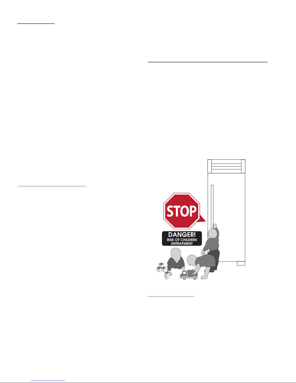
PROPER DISPOSAL OF THE OLD
REFRIGERATOR
Child entrapment and suffocation are not problems
of the past. Junked or abandoned refrigerators are
still dangerous...Even if they will sit for “just a few
days”. If you are getting rid of your old refrigerator,
please follow the instructions below to help prevent
accidents.
BEFORE YOU THROW AWAY YOUR OLD
REFRIGERATOR OR FREEZER:
• Take off the doors.
• Leave the shelves in place so that children may
not easily climb inside.
CFC DISPOSAL
Your old refrigerator may have a cooling system that
used CFCs (chlorofluorocarbons). CFCs are believed
to harm stratospheric ozone. If you are throwing away
your old refrigerator, make sure the CFC refrigerant
is removed for proper disposal by a qualified service.
If you intentionally release this CFC refrigerant you
can be subject to fines and imprisonment under
provisions of the environment legislation.

3
30 INCH COLUMNS
3 - 5
si t e p r e p a r a t i O n
el e c t r i c a l r e q u i r e m e n t s
PRESERVE THE MOMENT®

4TRUE RESIDENTIAL®
SITE PREPARATION
• Rough Opening dimensions. (See figure 1)
• For FLUSH installations the front face of the unit will be flush with the surrounding cabinets. (See figure 2)
• For PROUD (Standard) installations, the front face of the unit will extend beyond cabinets. (See figure 3)
TOP VIEW
FIGURE 2 - FLUSH INSTALL
TOP VIEW
FIGURE 3 - PROUD INSTALL
23 25/32"
604mm
PROUD INSTALL
25 25/32"
655mm
FLUSH INSTALL
TR-30REF-R-SG-A
R
23 25/32"
604mm
PROUD INSTALL
25 25/32"
655mm
FLUSH INSTALL
TR-30REF-R-SG-A
R
FRONT VIEW
FIGURE 1 - ROUGH OPENING
& ELECTRICAL AREA
84"
(2134 mm)
PROUD
INSTALL
841/4"
(2140 mm)
FLUSH
INSTALL
77"
(1956 mm)
2"
(51 mm)
8"
(204 mm)
Electrical located
in this area.
301/4"
(769 mm)
293/4"
(756 mm)
FLUSH
INSTALL
PROUD
INSTALL
TR-30
FLUSH OPENING DIMENSIONS PROUD OPENING DIMENSIONS
Width Depth Height
29 ¾" 23 ⁄"84"
Width Depth Height
30 ¼" 25 ⁄"84 ¼"
NOTE: DIMENSIONS MAY VARY BY ± 1/8”
* BECAUSE OF THE WEIGHT OF THIS UNIT, IT IS RECOMMENDED TO CONSULT A FLOORING EXPERT PRIOR TO INSTALLATION. THE
FLOORING BENEATH THE UNIT SHOULD BE RATED TO SUPPORT AT LEAST 150 POUNDS PER SQUARE FOOT.
NOTE: IT IS NOT RECOMMENDED TO INSTALL UNITS SIDE BY SIDE WITH HINGES TOUCHING EACH
OTHER. IF YOU PLAN TO INSTALL UNITS HINGE TO HINGE, CALL TECH SUPPORT AT 844-746-9423 FOR
INSTALLATION INSTRUCTIONS.

5
30 INCH COLUMNS
TOP VIEW
FRONT VIEW SIDE VIEW
83 15/16"
2132mm
30"
762mm
67 29/32"
1725mm
DOOR
HEIGHT
72 5/8"
1845mm
25 25/32"
655mm
27 29/32"
709mm
30 15/32"
774mm
2 9/16"
65mm
3 15/16"
100mm
90°
55 1/4"
1403mm
23 25/32"
604mm
29 15/32"
748mm
31 15/32"
799mm
29 9/16"
751mm
135°
20 11/16"
525mm
TR-30DZW-R-SG-A
R
83 15/16"
2132mm
30"
762mm
67 29/32"
1725mm
DOOR
HEIGHT
72 5/8"
1845mm
25 25/32"
655mm
27 29/32"
709mm
30 15/32"
774mm
2 9/16"
65mm
3 15/16"
100mm
90°
55 1/4"
1403mm
23 25/32"
604mm
29 15/32"
748mm
31 15/32"
799mm
29 9/16"
751mm
135°
20 11/16"
525mm
TR-30DZW-R-SG-A
R
30"
762mm
67 29/32"
1725mm
DOOR
HEIGHT
72 5/8"
1845mm
83 15/16"
2132mm
25 25/32"
655mm
27 29/32"
709mm
30 15/32"
774mm
2 9/16"
65mm
3 15/16"
100mm
135°
20 19/32"
523mm
23 25/32"
604mm
55 1/4"
1403mm
29 15/32"
748mm
31 15/32"
799mm
90°
29 9/16"
751mm
TR-30REF-R-SS-A
R
30"
762mm
67 29/32"
1725mm
DOOR
HEIGHT
72 5/8"
1845mm
83 15/16"
2132mm
25 25/32"
655mm
27 29/32"
709mm
30 15/32"
774mm
2 9/16"
65mm
3 15/16"
100mm
135°
20 19/32"
523mm
23 25/32"
604mm
55 1/4"
1403mm
29 15/32"
748mm
31 15/32"
799mm
90°
29 9/16"
751mm
TR-30REF-R-SS-A
R
NOTE: DIMENSIONS MAY VARY BY ± 1/8”

6TRUE RESIDENTIAL®
ELECTRICAL REQUIREMENTS
For all built-in models, the electrical supply should be located within the shaded area shown in
the illustration. Follow the National Electrical Code and local codes and ordinances when installing
the receptacle. A dedicated circuit, supplying only this appliance is required. A ground fault circuit
interrupter (GFCI) is not recommended and may cause interruption of operation.
NOTES:
• THE OUTLET MUST BE CHECKED BY A QUALIFIED ELECTRICIAN TO BE
SURE THAT IT IS WIRED WITH THE CORRECT POLARITY.
• VERIFY THAT THE OUTLET IS PROPERLY GROUNDED.
• POWER SUPPLY 115 V AC, 60 HZ
• CIRCUIT BREAKER 15 AMP
• RECEPTACLE 3-PRONG GROUNDING-TYPE
FRONT VIEW
ROUGH OPENING &
ELECTRICAL AREA
84"
(2134 mm)
PROUD
INSTALL
841/4"
(2140 mm)
FLUSH
INSTALL
77"
(1956 mm)
2"
(51 mm)
8"
(204 mm)
Electrical located
in this area.
301/4"
(769 mm)
293/4"
(756 mm)
FLUSH
INSTALL
PROUD
INSTALL

7
30 INCH COLUMNS
7 - 11
PRESERVE THE MOMENT®
pl a n V i e w s
t r - 3 0 / t r - 3 0
t r - 3 0 / t r - 3 0 / t r - 3 0
t r - 3 0 / t r - 4 8
t r - 3 0 / t r - 4 2

8TRUE RESIDENTIAL®
FLUSH VS. PROUD INSTALL
PLAN VIEW
TR-30 / TR-42
ROUGH OPENING & ELECTRICAL AREA
FLUSH OPENING DIMENSIONS PROUD OPENING DIMENSIONS
Width Depth Height
71¾" 23 ⁄"84"
Width Depth Height
72¼" 25 ⁄"84 ¼"
23 25/32"
604mm
PROUD INSTALL
25 25/32"
655mm
FLUSH INSTALL
TR-42,30DZW
R
23 25/32"
604mm
PROUD INSTALL
25 25/32"
655mm
FLUSH INSTALL
TR-42,30DZW
R
71 3/4" PROUD INSTALL
72 1/4" FLUSH INSTALL
84"
PROUD
INSTALL
84 1/4"
FLUSH
INSTALL
77"
2"
7" TYP
30 1/8"
TR-42,30DZW
R
72 1/32"
1829mm
83 15/16"
2132mm
3 15/16"
100mm
30 15/32"
774mm
2 9/16"
65mm
25 25/32"
655mm
27 29/32"
709mm
TR-42,30DZW
R
NOTE: DIMENSIONS MAY VARY BY ± 1/8”

9
30 INCH COLUMNS
TR-30 / TR-48
FLUSH OPENING DIMENSIONS PROUD OPENING DIMENSIONS
Width Depth Height
77¾" 23 ⁄"84"
Width Depth Height
78¼" 25 ⁄"84 ¼"
FLUSH VS. PROUD INSTALL
PLAN VIEW
23 25/32"
604mm
PROUD INSTALL
25 25/32"
655mm
FLUSH INSTALL
TR-48,30DZW
R
23 25/32"
604mm
PROUD INSTALL
25 25/32"
655mm
FLUSH INSTALL
TR-48,30DZW
R
77 3/4" PROUD INSTALL
78 1/4" FLUSH INSTALL
84"
PROUD
INSTALL
84 1/4"
FLUSH
INSTALL
77"
2"
7" TYP
30 1/8"
TR-48,30DZW
R
83 15/16"
2132mm
78 1/32"
1982mm
3 15/16"
100mm
27 29/32"
709mm
25 25/32"
655mm
30 15/32"
774mm
2 9/16"
65mm
TR-48,30DZW
R
NOTE: DIMENSIONS MAY VARY BY ± 1/8”
ROUGH OPENING & ELECTRICAL AREA

10 TRUE RESIDENTIAL®
TR-30 / TR-30
FLUSH OPENING DIMENSIONS PROUD OPENING DIMENSIONS
Width Depth Height
59¾" 23 ⁄"84"
Width Depth Height
60¼" 25 ⁄"84 ¼"
FLUSH VS. PROUD INSTALL
PLAN VIEW
23 25/32"
604mm
PROUD INSTALL
25 25/32"
655mm
FLUSH INSTALL
TR-30REF,30DZW
R
23 25/32"
604mm
PROUD INSTALL
25 25/32"
655mm
FLUSH INSTALL
TR-30REF,30DZW
R
59 3/4" PROUD INSTALL
60 1/4" FLUSH INSTALL
84"
PROUD
INSTALL
84 1/4"
FLUSH
INSTALL
77"
2"
7" TYP
30 1/8"
TR-30REF,30DZW
R
60 1/32"
1525mm
83 15/16"
2132mm
3 15/16"
100mm
25 25/32"
655mm
27 29/32"
709mm
30 15/32"
774mm
2 9/16"
65mm
TR-30REF,30DZW
R
NOTE: DIMENSIONS MAY VARY BY ± 1/8”
ROUGH OPENING & ELECTRICAL AREA

11
30 INCH COLUMNS
TR-30 / TR-30 / TR-30
FLUSH OPENING DIMENSIONS PROUD OPENING DIMENSIONS
Width Depth Height
89 ¾" 23 ⁄"84"
Width Depth Height
90¼" 25 ⁄"84 ¼"
FLUSH VS. PROUD INSTALL
PLAN VIEW
23 25/32"
604mm
PROUD INSTALL
25 25/32"
655mm
FLUSH INSTALL
TR-30REF,30FRZ,30DZW
R
23 25/32"
604mm
PROUD INSTALL
25 25/32"
655mm
FLUSH INSTALL
TR-30REF,30FRZ,30DZW
R
89 3/4" PROUD INSTALL
90 1/4" FLUSH INSTALL
84"
PROUD
INSTALL
84 1/4"
FLUSH
INSTALL
77"
2"
7" TYP
30 1/8" 30 1/8"
TR-30REF,30DZW
R
83 15/16"
2132mm
90 1/32"
2287mm
3 15/16"
100mm
25 25/32"
655mm
27 29/32"
709mm
30 15/32"
774mm
2 9/16"
65mm
TR-30REF,30FRZ,30DZW
R
ROUGH OPENING & ELECTRICAL AREA

12 TRUE RESIDENTIAL®
12 - 15
an t i -t i p B r a c k e t i n s t a l l a t i O n
le V e l i n g t h e u n i t
PRESERVE THE MOMENT®

13
30 INCH COLUMNS
ANTI-TIP BRACKET KIT:
• One (1) anti-tip bracket (Figure 1.1)
• Four (4) masonry 3/16” screws
• Eight (8) wood #12 – 2” screws
• Twelve (12) 1/4” washers
FOR ALL FULL SIZE RESIDENTIAL MODELS, THE ANTI-
TIP BRACKET ENGAGES WITH THE REAR LEVELING
LEGS TO SECURE THE UNIT. FOLLOW THESE STEPS
TO SECURE THE BRACKET BEFORE MOVING THE
UNIT INTO FINAL OPERATING POSITION.
1. Determine final location of the unit. For a FLUSH
install, measure back 24-31/32” (Dimension A)
from the surrounding cabinetry. For a PROUD
install, measure back 22-31/32” (Dimension B)
from the surrounding cabinetry. For either type of
install, place the anti-tip bracket centered in the
rough opening.
2. Using the bracket as a guide, drill pilot holes into the
wall/floor. It is recommended to secure the bracket
to as many floor joists and wall studs as possible.
3. Using the provided screws and washers, secure the
bracket to the wall/floor. Adjust the rear rollers to
just above their lowest position and move the unit to
its final position. Raise the rear rollers a minimum
of 1/8” to engage the bracket.
FIGURE 1.1 - ANTI-TIP BRACKET
987036
5.19.17 AL
TRUE RESIDENTIAL REFRIGERATION
UPRIGHT ANTI-TIP BRACKET INSTALLATION
30 INCH UNIT
22 31/32"
583mm
PROUD INSTALL
24 31/32"
634mm
FLUSH INSTALL
9 9/32"
236mm
9 9/32"
236mm
C
LC
L
TR-30REF-R-SG-A
R
NOTE: DIMENSIONS MAY VARY BY ± 1/8”

14 TRUE RESIDENTIAL®
NOTES:
• DUE TO THE WEIGHT OF UNITS, IT IS RECOMMENDED TO CONSULT A FLOORING EXPERT
PRIOR TO INSTALLATION. THE FLOORING BENEATH THE UNIT SHOULD BE RATED TO SUPPORT
AT LEAST 150 POUNDS PER SQUARE FOOT.
• EIGHT (8) ¼-20 X 1" LAG BOLTS SECURING THE UNIT TO THE SKID DURING SHIPPING MAY
ALSO BE USED ON THE INSTALLATION OF THE ANTI-TIP BRACKET.
WARNING
!
TIP OVER HAZARD
A child or adult could tip the refrigerator resulting in property damage or bodily harm. Follow these instructions
to properly install the anti-tip device. If the unit is moved, verify the device is properly engaged before normal
usage of unit commences.
48 INCH UNIT
22 31/32"
583mm
PROUD INSTALL
24 31/32"
634mm
FLUSH INSTALL
9 9/32"
236mm
23 25/32"
604mm
9 9/32"
236mm
C
LC
LC
L
Anti-Tip Kit Install TR-48SBS-SS-B
R
NOTE: DIMENSIONS MAY VARY BY ± 1/8”
42 INCH UNIT
24 31/32"
634mm
FLUSH INSTALL
22 31/32"
583mm
PROUD INSTALL
20 25/32"
528mm
9 9/32"
236mm
9 9/32"
236mm
C
LC
LC
L
Anti-Tip Kit Install TR-42SBS-SS-B
R
NOTE: DIMENSIONS MAY VARY BY ± 1/8”

15
30 INCH COLUMNS
LEVELING THE UNIT
It is very important that the refrigerator sits level. This will insure that the doors will align and seal properly
and that the drain pans will not spill over.
TO LEVEL THE UNIT:
STEP 1. Place a level on the interior floor. Check and adjust so the unit is level from front to back, and left
to right.
STEP 2. Adjust the front legs using a set of pliers or a wrench.
STEP 3. Adjust the rear using a 7/16" socket and ratchet. Turn clockwise to raise the rear of the unit.
LEG ADJUSTMENTS
REAR LEG
ADJUSTMENT
FRONT LEG
ADJUSTMENT

16 TRUE RESIDENTIAL®
16 - 22
Ba s i c e l e c t r O n i c c O n t r O l O p e r a t i O n s
re f r i g e r a t O r a n D f r e e z e r
PRESERVE THE MOMENT®
Table of contents
Other True Refrigerator manuals
Popular Refrigerator manuals by other brands

Norcold
Norcold MRFT630C parts list

Montpelier
Montpelier MICL88 Installation and operating instructions

Koolatron
Koolatron KCR-48B owner's manual

GE
GE GTZ18GCESS Owner's Manual & Installation Instructions

Frigidaire
Frigidaire FRT21LR7A Factory parts catalog

Bosch
Bosch KAN62V40 Operating and installation instructions