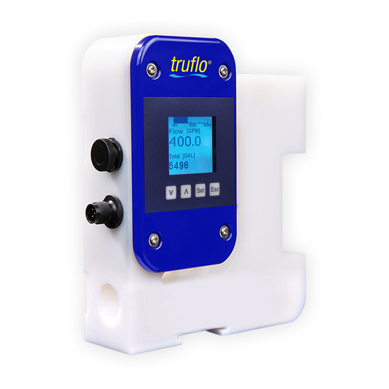
truflo TIB Series User manual

TIB SERIES
INSTRUCTION MANUAL
Battery Operated Paddle Wheel Flow Meter
TIB SERIES
Read the User's Manual Carefully.
Manufacturer Reserves the Right to Implement Changes Without Prior Notice.


General Data
02
Battery Operated Paddle Wheel Flow Meter
TIB SERIES
Specification Description
Battery Lithium Battery | 3 VDC
Life of Battery 3 Years | Sleep Mode
Current Consumption 60mA max.
Flow Totalizer GAL | LTR 0 -999999
Flow Rate GPM | LPM 0.0 -999.9 GPM
Fluid Water | Liquid Chemicals
Accuracy ± 0.5% of F.S. @ 25°C
Response frequency 5K Hz
Max Flow Rate 10m/s | 33ft/s
Min Flow Rate 0.1m/s | 0.3ft/s
Materialsof Construction Paddle | ETFE Tefzel®
Rotor | Bushings | Zirconium Ceramic
Sensor Body | PVC | PP | PVDF
O-Ring Material Viton (std) | EPDM*
Operating Temperature PVC < 60°C | PP < 80°C | PF < 100°C
Protection Class IP-65 | General Purpose
Approval CE | RoHS
*Optional
1. De-pressurize and Vent System Prior to Installation or Removal.
2. Confirm Chemical Compatibility Before Use.
3. DO NOT Exceed Maximum Temperature or Pressure Specifications.
4. ALWAYS Wear Safety Goggles or Face-Shield During Installation and/or Service.
5. DO NOTAlter Product Construction.
Safety Information
WARNING!
Indicates a potential hazard. Failure to follow all
warnings may lead to equipment damage, injury, or
death
Warning | Caution | Danger
Overtightening may permanently damage product
threads and lead to failure of the retaining nut.
Hand Tighten Only
Use of tool(s) may damage product beyond repair
and potentially void product warranty.
Do Not Use Tools
Always utilize the most appropriate PPE during
installation and service of Truflo products.
Personal Protective Equipment (PPE)
Sensor may be under pressure, take caution to vent
system prior to installation or removal. Failure to do so
may result in equipment damage and/or serious injury.
Pressurized System Warning
Highlights additional information or detailed
procedure.
Note | Technical Notes

03
Battery Operated Paddle Wheel Flow Meter
TIB SERIES
TIB Series
OP1 FTM OP2 GPM
Very Important
Lubricate O-rings with a Viscous Lubricant Compatible
with the Materials of Construction.
Using an Alternating | Twisting Motion Carefully Lower
the Sensor into the Fitting. | Do Not Force | Fig 5
Ensure Tab | Notch are Parallel to Flow Direction | Fig-2
Ensure Amble Silicon Grease
(Supplied) is Applied Prior to Insertion Ensure Location Tabs
Are Parallel to Direction of Flow
Fig-3
Screw Down
Retention Cap
Ensure O-Rings
are well Greased
Lubricate (Grease)
Inside of Insertion
Fitting
Positioning Tab
Notch
1¼" NPT
Fig-5
Hand Tighten the Sensor Cap. DO NOT use any tools on the sensor cap
or the cap threads or fitting threads may be damaged. | Fig-5
Process Pipe
(Top View)
Flow
Sensor Blade
Ensure Tab
is Parallel to
Flow Direction
Fig-4
TIB Series
OP1 FTM OP2 GPM
01 02 03
Engage one Thread of the Sensor Cap
then turn the Sensor until the Alignment
Tab is Seated in the Fitting Notch,
Ensure Tab is Parallel to Flow Direction.
Flow Meter Positioning Tab and
Clamp Saddle
Notch
Hand Tighten the Screw Cap.
DO NOT use any Tools, Threads
may be Damaged.
Ensure Meter is Firmly in Place
Notch
Flow Meter
Very Important
Lubricate O-rings
with a Viscous
Lubricant
Compatible
with the System
Correct Sensor Installation
Tab
Notch
Fig-1 Fig-2
Installation
Retention Cap
Flow

04
Battery Operated Paddle Wheel Flow Meter
TIB SERIES
* Maximum % Solids: 10% with particle size not exceeding 0.5 mm cross section or length.
Reducer
90° Elbow | Flow Upward
Flange
Outlet Outlet
2 X 90° Elbow
Inlet OutletInlet
OutletInlet
10xID 5xID 25xID 5xID 15xID 5xID
25xID 5xID 20xID 5xID
Good if NO
Sediment Present Good if NO Air
Bubbles Present Preferred Installation if Sediment* or Air
Bubbles may be Present
Installation Positions
Figure 1 Figure 2 Figure 3
Developed Turbulent Flow
Velocity
Profile
Flow
Ball Valve
OutletInlet
20xID 5xID
Correct Sensor Positioning
TIB
and
Series Flow Meters measure liquids only. No air bubbles should be present
the pipe must always be full. The sensors are not effective in laminar or
transitional flow applications. Minimum Reynolds number required is 4500.
For accurate flow measurement there must be a developed turbulent velocity
profile at the sensor location. This requires a straight run pipe with a minimum
number of pipe diameters distance upstream and downstream of the flow
sensor. These distances depend on the type of piping element (i.e. valves,
elbows, reducers etc.) causing the disturbance. To ensure maximum accuracy,
the following guidelines need to be observed when installing.
90° Elbow | Flow Downward
Inlet Outlet
Inlet

05
Battery Operated Paddle Wheel Flow Meter
TIB SERIES
Long Service Life
Maximum Pressure | Temperature
10
20
30
40
50
60
70
80
90
100
110
120
130
140
150
160
170
180
190
200
210
.7
1.4
2.1
2.8
3.4
4.1
4.8
5.5
6.2
6.9
7.6
8.3
9.0
9.7
10.3
11.0
11.7
12.4
13.1
13.8
14.5
(psi) (bar)
0-20 020 40 60 80 100
°F
°C -4 32 68 104 140 176 212
PVDF
Polypropylene
PVC
Note: During system design the specifications of
all components must be considered. | Non-Shock
The TIB Series is equipped with a Zirconium Ceramic Rotor Pin
and 2 Bushings. The TIB Series also incorporates a contoured,
'Low Drag' Paddle Wheel leading to reduced drag, longer wear
and a higher accuracy.
Dimensions | Display
36.5
9.0
Ø84.0
98.0
TIB
Series TKT
Series
OP
1FT
MOP
2GP
M
ECO GAL KL GPM LPM TPM
LTR
Flow Rate
Flow Total
Battery Life
(Eco) = Extended Battery Life
Highlighted to Indicated
Programmed Unit of
Measurement
4Blade ETFE (Tefzel®) Rotor
•Open Channel Design Avoids Cavitation
•Re-Designed Contoured Paddle
Integrated Solid State Electronics
•Encapsulated in Epoxy
Sensor Body
•Available in PVC | PP | PVDF
•2 Sensor Lengths to Measure 2" to 24" Pipes
Ceramic Rotor |Bushings
Rotor
Contoured
Paddle
High Chemical Resistance
Long Life - 40 years/m/s
Self Cleaning Design
•
•
•

06
Battery Operated Paddle Wheel Flow Meter
TIB SERIES
Current Flow Rate | Total
0-1
Programming
OPERATION
RANGE
DISPLAY
STEPS
Home Screen
Press & (HOLD)
Step-1
Screen Lock
Step-2 Programming Lock Out Feature
LCK= '0' Unlocked : Factory Default
LCK= '1' Locked
3 sec
Press Key
0.1-9999
K Factor
Step-3
Programming Display Units
OPERATION
RANGE
DISPLAY
STEPS
Display Units
Press (HOLD)
Step-1 Press to Select & Press To Confirm
Press
non | Eco
Display Mode
Step-4
dSP.non - LED Back Light | Default is set to 5 secs.
dSP-Eco - Back Light Function is not Active | Extended Battery Life
Press
Back Light Timer
Step-5
Time on for Back Light (Secs)
*Longer Time = Shorter Battery Life
Press
Flow Alarm Delay
Step-6
Press
Reset Totalizer
Step-7
rESEt.0 -Flow Totalizer Reset Disabled
rESEt.1(Default) -Flow Totalizer Reset Enabled
Press
Flow Rate - GPM | LPM | TPM
Flow Total - GAL | LTR | KL
1. Totalizer Reset Press Both Together for 3 Seconds
2. Sleep Mode Press for 3 Seconds to Reduce Power Consumption
3. Alarm Setup Press Both Together for 3 Seconds
Time Delay for Visual Alarm
3 sec
Press for Increase Value & Press for Decrease Value
Press to Save Value Press to Change Digit
1-9999
1-9999
Enter K Factor Value
See Chart on Page 9
0-1

07
Battery Operated Paddle Wheel Flow Meter
TIB SERIES
Battery Replacement Procedure

08
Battery Operated Paddle Wheel Flow Meter
TIB SERIES
04 05 06
01 02 03
08 0907
GENTLY tap pin with
Mallet or Hammer
GENTLY tap Rotor Pin
with Mallet or Hammer
Tap until Rotor is 50% out
Pull out Rotor Pin
Push in Rotor Pin
approx. 50%
Congratulations!
Replacement Procedure
Complete!
Pull Out Rotor Pin
entire way until
Paddle Wheel is loose
Paddle
Rotor Pin | Paddle Replacement Procedure
Insert New
Paddle in
Flow Meter
Rotor Hole
Line up Pin with Rotor Hole
Small Pin
Ensure Holes
are Aligned

1-¼"
1-¼"
CPVC Flange x 2
150 LB ANSI Flange
12. CPVC TEE FITTING (SCH80)
Socket Weld
CPVC Tee Style
Notch On Fitting
Ensure Notches
are Parallel to
Direction of Flow
Remember to Grease
Flowmeter & Fitting
09
Battery Operated Paddle Wheel Flow Meter
TIB SERIES
Pipe Size (O.D.) ANSI (ID) (Inches)
Sch (40) Sch (80)
DIN (ID)
(mm)
Flow Rate (LPM) / USGPM
0.3m/s min. 10m/s max.
1/2" | DN15 Ø20 3.5 | 1.0 120 | 32
3/4" | DN20 Ø25 5 | 1.5 170 | 45
1" | DN25 Ø32 9 | 2.5 300 | 79
1 ½" | DN40 Ø50 25 | 6.5 850 | 225
2" | DN50 Ø63 40 | 10.5 1350 | 357
2 ½ Ø75 60 | 16 1850 | 357
3" | DN80 90 | 24 2800 | 739
4" | DN100 125 | 33 4350 | 1149
0.55
0.74
0.96
1.50
1.90
2.30
2.90
3.80
0.62
0.82
1.00
1.40
2.00
2.50
3.10
4.00
Ø78
Ø96.50
Min | Max | Flow Rates
6" | DN150 Ø150 230 | 60 7590 | 1997
8" | DN200Ø200 315 | 82 10395 | 2735
5.70
7.56
6.06
7.94
K )DFWRU7DEOHV
Tee Fitting (Unit:inch)
Size DN Id
½"
¾"
1"
1-¼"
1-½"
2"
2-½"
3"
4"
15
20
25
32
40
50
65
80
100
0.55
0.74
0.96
1.30
1.50
1.90
2.30
2.90
3.83
1013.04
604.80
408.24
250.40
139.86
81.65
54.43
34.96
19.80
S
S
S
S
S
S
S
S
S
K-Factor
Sensor
Length
CPVC | SCH80
Clamp Saddles
Size DN Id
2"
3"
4"
6"
8"
50
65
80
100
150
1.9
2.3
2.9
3.8
5.7
81.65
34.96
19.80
9.18
5.21
S
S
S
L
L
K-Factor
Sensor
Length
CPVC | SCH80
Tee Fitting (Unit:inch)
Size DN Id
2"
2-½"
3"
4"
6"
8"
10"
12"
14"
16"
20"
24"
50
65
80
100
150
200
250
300
350
400
500
600
1.9
2.3
2.9
3.8
5.7
7.0
9.5
11.3
12.4
15.1
19.0
21.0
81.65
54.43
34.96
19.80
9.18
5.21
3.43
2.45
1.77
1.36
0.86
0.60
S
S
S
S
L
L
L
L
L
L
L
L
K-Factor
Sensor
Length
CPVC | SCH80
TEE FITTINGS CLAMP-ON SADDLES CPVC SOCKET WELD-ON
ADAPTERS
4
"
Warranty Information
All warranty and non-warranty repairs being returned must include The RGA number and a fully completed Service
Form and Flow Meter. must be returned to Icon Process Controls directly or to the authorized distributor. Product
returned without a RGA number and Service Form will not be warranty replaced or repaired. Truflo Flow Meters are
warranted out of box but not against any damage, due to Process or Misapplication Failures e.g. High Temperature,
Chemical Attack or Physical Mishandling of Product.

TIB SERIES
Battery Operated Paddle Wheel Flow Meter
TIW
Flow Transmitter
Frequency Pulse Output
TIP
Flow Rate + Flow Total
Pulse | RS485
TIR
Pulse + 4-20mA
TIM
Flow Rate + Total Pulse | 4-20mA
TI Series Products
•Industry's Highest Accuracy: ±0.50%
•PVC | PP | PVDF
•Retrofits into Signet® Fittings
•Size Range - ½" - 24"
•Low Pressure Drop
•Password Protected Security
•Lifetime Warranty on Paddle Wheel Assembly
10

FLOW + PRESSURE + LEVEL + TEMP
for more information visit www.iconprocon.com
for more information visit www.iconprocon.com
Table of contents
Other truflo Measuring Instrument manuals
truflo
truflo ULTRAFLO 5000 User manual
truflo
truflo UltraFlo 500 Series User manual
truflo
truflo TIM Series Instruction manual
truflo
truflo TK Series User manual
truflo
truflo TKS Series Instruction manual
truflo
truflo TIP Series User manual
truflo
truflo OBS-LE Series User manual
truflo
truflo ICON TIR Series User manual
truflo
truflo TKB Series Instruction manual

truflo
truflo TKB Series User manual

