TRUlink 40481 User manual

1
USER GUIDE
MULTI-FUNCTION CONVERTER
Model: 40481

1
Introduction....................................................................................................................................................2
Features........................................................................................................................................................3
Package Contents.........................................................................................................................................4
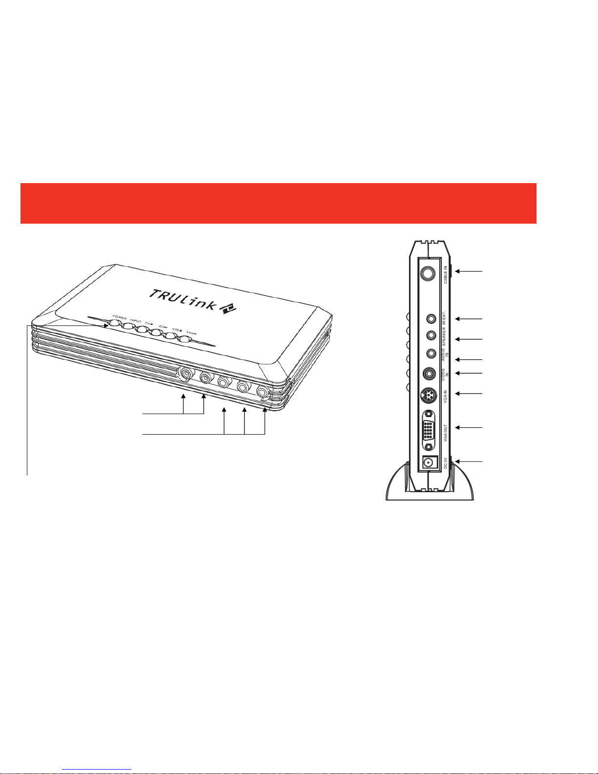
Device Overview...........................................................................................................................................5
Device Installation to a Display for TV Function............................................................................................6
Device Installation to a PC and Display........................................................................................................8
Device Installation Using a Component Video Connection.........................................................................10
Device Installation Using a Composite Video Connection..........................................................................11
Example Application Diagrams...................................................................................................................12
Remote Control Functions..........................................................................................................................13
Favorite Channel Operation........................................................................................................................21
Troubleshooting...........................................................................................................................................23
Technical Specifications..............................................................................................................................24
Warranty.....................................................................................................................................................25
Important Safety Information.......................................................................................................................26
TABLE OF CONTENTS

2
Thank you for purchasing the TruLink™ Multi-Function Converter. With this device you make your PC
monitor a dual-purpose screen for both computer and TV video. The Converter accepts component or
composite video signals and upconverts them to VGA. Connect a cable television feed and watch television
programs on your computer monitor. Picture-In-Picture (PIP) allows you to watch content on your monitor in
a separate window while surfing the internet, paying bills or doing school work. The pass-through function
sends VGA video directly to the monitor from your computer when the Converter is powered down. MTS
stereo output via a 3.5mm stereo jack is compatible with Dolby Pro-Logic™ for a complete theater
experience. We recommend that you read this manual thoroughly and retain for future reference.
INTRODUCTION

3
Converts composite video or component video to VGA
125 channel cable ready tuner
Display home theater sources, gaming systems and camcorders on your flat panel
Use in a school dorm to turn you standard PC monitor into a television
Output resolution up to 1920 x 1200 for 24 bit RGB true color
Plug-n-Play, no software required
FEATURES

4
Multi-Function Converter (1)
Remote Control (1)
Unit Stand (1)
3ft. Video cable (HD15 to 8-pin din) (1)
6ft. 3.5mm Stereo Audio M/M cable (1)
Power Supply
PACKAGE CONTENTS

5
DEVICE OVERVIEW
Component Video
Input
Audio Input
Rear View
CATV Input
IR Extender Port
3.5mm Speaker
Output
3.5mm Audio Input
RCA Video Input
VGA Input
VGA Output
5V DC Power
Input
POWER: Turns the Multi-Function
Converter On and off
INPUT: Toggles through the device
inputs
CH+ -: Changes the CATV channel
up and down
VOL+ -: Changes the speaker
volume up and down

6
STEP 1
Place your Multi-Function Video Converter near your display.
STEP 2
Connect the CATV cable to the “CABLE IN” jack on the back panel.
STEP 3
Connect the monitor’s VGA cable to the “VGA OUT” jack on the back panel of the Multi-Function Converter.
Tighten the screws as a loose connection can cause picture distortion.
STEP 4
Connect your multimedia (computer) speaker (please note the connector should be 3.5mm male stereo
type) to “SPEAKER” on the back panel.
STEP 5
Connect the supplied 3.5mm audio cable to the speaker output of your PC sound card and the opposite end
to the “AUDIO IN” on the back panel of the Multi-Function Converter.
STEP 6(OPTIONAL)
Connect an IR receiver extender to the “IR EXT” on the back panel of the Multi-Function Converter, and
route the emitter to an exposed area to receive signal from the remote.
DEVICE INSTALLATION TO A DISPLAY FOR TV FUNCTION

7
STEP 7
Connect the supplied AC/DC adapter to “DC 5V” on the back panel of the Multi-Function Converter and plug
the other end into an AC outlet.
STEP 8
Turn on your monitor and then push the “POWER” key on the Multi-Function Converter. You should have a
TV image on your LCD or CRT screen. Turn off the Multi-Function Converter and your computer should be
displayed.
DEVICE INSTALLATION TO A DISPLAY FOR TV FUNCTION
LCD or PDP
S
p
eakers
CATV
Back View
IR Extending Receiver (optional)
Power Su
pp
l
y

8
STEP 1
Connect the RF cable for the CATV to “CABLE IN” on the Multi-Function Converter.
STEP 2
Connect a VGA cable from your display to the “VGA OUT” on the back panel of the Multi-Function Converter.
Take the supplied VGA cable and connect the 8-pin end into the “VGA IN” on the back panel of the
Multi-Function Converter and connect the HD15 (VGA) connector to your PC.
STEP 3
Connect your speakers to the “SPEAKER” output on the back panel of the Multi-Function Converter.
Take the 3.5mm to 3.5mm audio cable, and connect one end to the “AUDIO IN” on the back panel of the
Multi-Function Converter, and the other end to your PC.
DEVICE INSTALLATION TO A PC AND DISPLAY

9
STEP 4
Connect the Power Supply to the unit and connect the other end to your AC outlet.
STEP 5
Turn on your display and the Multi-Function Converter. Press the “Input” key to “TV mode” and there
will be a label which shows “CATV”.
DEVICE INSTALLATION TO A PC AND DISPLAY
LCD or PDP
S
p
eakers
CATV
Power Su
pp
l
y
VGA Cable
3.5mmAudio Cable
PC VGA Port
Back View

10
STEP 1
Make the connection to your display as you would in the previous two Device Installation sections.
STEP 2
Take a component video cable (not included), and connect one end to the YPbPr output of your source
device (game console, DVD/VCR, etc.). Connect the other end of the component video cable to the “YPbPr”
input of the front panel of the Multi-Function Converter. Please note, the color coded cables should be the
same between the video source and the Multi-Function Converter. The wrong connection can cause no
picture or the wrong color for your image.
STEP 3
Take a stereo audio L/R cable, and connect one end to your source device, and the other end to the “stereo
audio L/R” input on the front panel of the Multi-Function Converter.
STEP 4
Use the supplied Power Supply and connect the DC end to the Multi-Function Converter and the other end to
an AC outlet.
STEP 5
Power up your source device, display, and Multi-Function Converter. Use the remote control or the top panel
INPUT key to switch to the component or YPbPr input, and you should see your picture.
An Application Diagram is on page 12.
DEVICE INSTALLATION USING A COMPONENT VIDEO CONNECTION

11
STEP 1
Make the connections to your display as you would in the first two Device Installation sections.
STEP 2
Using a composite RCA video cable, connect one end to the video output of your source device, and the
other end to the “VIDEO IN” of the Multi-Function Converter.
STEP 3
Take a stereo audio L/R cable, and connect one end to your source device, and the other end to the “stereo
audio L/R” input on the front panel of the Multi-Function Converter.
STEP 4
Use the supplied Power Supply and connect the DC end to the Multi-Function Converter and the other end to
an AC outlet.
STEP 5
Power up your source device, display, and Multi-Function Converter. Use the remote control or the top panel
INPUT key to switch to the composite input, and you should see your picture.
An Application Diagram is on page 12.
DEVICE INSTALLATION USING A COMPOSITE VIDEO CONNECTION

12
Device installation using a component video connection
Device installation using a composite video connection
EXAMPLE APPLICATION DIAGRAMS
DV
DVD
Front View
Front ViewRea
r
View

13
REMOTE CONTROLLER FUNCTIONS
VOL+/VOL-
CH +/CH-
( 1) Second Audio Program Select
( 3 ) Mute
( 5 ) CH+/CH-
( 6 ) operation with
menu key /switch
for PIP audio
( 8 )MENU
( 11 ) change channel within Favorite channel group
(12 ) Favorite Channel
( 14 )OSD
( 2 ) Power
( 4 ) Input Source
( 7 ) VOL+/VOL-
( 9 ) exit
( 10 ) Numeric Key
( 13 ) Return to LAST channel
( 15 ) PIP
( 17 ) Resolution
( 16 ) Channel Preview

14
( 1 ) MTS: Select the second audio program.
( 2 ) POWER:
Normally, this box is under “STANDBY” mode. The computer signal will loop through to your monitor.
If you push this key, and this device is active, you can watch television and use video sources
connected to this box.
Note: You must make all the connections that are described previously and your computer
should be on with an active VGA card.
( 3 ) MUTE:
You can mute the audio from a video source device by pushing this key. Re-push this key or press
VOL+/- key to deactivate mute.
( 4 ) INPUT:CHANGE THE INPUT SOURCE DEVICE
Different video sources can be connected to this device. This key will switch between those
different sources.
Note: This function is active only when the Converter is turned on. The process is cyclic:
TV→Video→YPbPr→PC
( 5 ) CHANNEL UP/DOWN:
Press “▲”or”▼” to select the adjacent channel
Note: Only valid when the Converter is turned on,
and the source should be CATV.
REMOTE CONTROLLER FUNCTIONS

15
( 6 ) SELECT:
This is only valid under MENU operation and PIP function.
( 7 ) VOLUME UP/DOWN:
Press “◄”or”►” to adjust the volume of the signal source.
Note: Only valid when the Converter is on. Under standby mode, this function is not active.
( 8 ) ADVANCED OPERATION WITH MENU FUNCTION:
When you press the “MENU” key on the remote control, there will display a main screen as illustrated,
use ▲or ▼arrow key to choose an item, then press “►”key to enter the next MENU screen, then use
▲or ▼key to highlight the item that you want to change and press the “Select” key on the remote
control, and use ◄or ►key to adjust the parameter.
REMOTE CONTROLLER FUNCTIONS

16
PICTURE OPERATION
BRIGHTNESS
CONTRAST
COLOR
TINT
SHARPNESS
Press ▲or ▼key for desired item, press ”Select”
key for confirmation, press”◄” or “►” to adjust the
value
Brightness : press”◄” or “►” to adjust the value
to meet your requirement
CONTRAST :press”◄” or “►” to adjust the
contrast that meets your need.
COLOR:press”◄” or “►” to adjust the color that
you like
TINT:press”◄” or “►” to adjust the tint for this
device
SHARPNESS :press”◄” or “►” to adjust the
sharpness of this device
TV FUNCTION
OPERATION
TV SYSTEM
CHANNEL EDIT
FINE TUNE
CHANNEL SCAN
AUTO SCAN
MTS
▲▼key for desired item, press ”Select” key for
confirmation, press”◄” or “►” to adjust the value
TV SYSTEM:CATV
CHANNEL EDIT:ADD Channel or delete channel
FINE TUNE:If there is some channel that does
not show up correctly, you can adjust to get a
better picture.
CHANNEL SCAN:Scan all the available
channels in your area
AUTO SCAN:Not functional with this device
MTS:Second Audio Program
REMOTE CONTROLLER FUNCTIONS

17
INPUT SOURCE OPERATION
TV
Video
YPBPR
PC
▲▼key for desired item, press ”Select” key for
confirmation
TV:Watch CATV TV Program
Video : View the AV input
YPBPR:View the Component Video
PC:Under PC mode
RESOLUTION OPERATION
1024 x 768
1280 x 1024
1280 x 768
1366 x 768
1440 x 900
1680 x 1050
1920 x 1200
▲▼key for desired item, press ”Select” key for
confirmation
Note: The maximum resolution of this device is
1920X1200. You must make sure that your
monitor supports this resolution.
REMOTE CONTROLLER FUNCTIONS

18
( 9 ) EXIT:
Press “EXIT” to exit the menu.
( 10 ) NUMERIC KEY 0~9:
You can directly press the number key to select the channel.
NOTE:
1. The Converter should be turned on and the source should be CATV.
2. If you want to watch channels above 100,please input the number 3 digit.
OSD SETTING OPERATION
LANGUAGE
TRANSPARENT
INFORMATION
SLEEP
RESET
Press ▲or ▼key for desired item, press ”Select”
key for confirmation, press”◄” or “►” to adjust
value
LANGUAGE: English for menu language
TRANSPARENT: Choose the OSD transparency
INFORMATION: Box information。
SLEEP: Auto shut-down function, you can choose
5/10/15/30/60/90/120 minutes or OFF
RESET: Reset this device to default setting
REMOTE CONTROLLER FUNCTIONS

19
( 11 ) FAVORITE CHANNEL SCAN (FC SCAN): More information for this in “Favorite Channel Operation” section.
( 12 ) FAVORITE CHANNEL MEMORY (FC MEMO): More information for this in “Favorite Channel Operation”.
( 13 ) RETURN TO LAST CHANNEL (RCL):
If you want to return to the previous channel you watched, you can press this key.
NOTE: The Converter should be turned on, and the source should be CATV
( 14 ) OSD:
Press this key, and there will be a pop-up window in the upper-left side on your monitor screen that
shows the channel information and resolution.
( 15 ) PIP:
If you want to use the PIP function (meaning when you are working with a PC and want to watch
television at the same time), you can press the “PIP” key to enter PIP mode. There are 2 modes for
PIP window sizes, 1/4>1/9>PC mode, then you can adjust the position of the PIP window by
【▲】【▼】【◄】【►】on your remote control.
NOTE
If you want to use PIP, the VGA IN should have a signal coming in.
PIP will be available at the resolutions of: 1920X1200 , 1680X1050,
1440X900, 1366x768, 1280x768, 1280X1024, 1024X768.
Under PIP mode, channel up/down is done by the “CH+” or ”CH-“ key
If the input source is under YPbPr, PIP will be disabled. PIP is only valid for the “TV” or “Video” signal
source
REMOTE CONTROLLER FUNCTIONS
Table of contents
Other TRUlink Media Converter manuals