Trumatic S 3002 P User manual

Trumatic S 3002 P / S 3002 / S 5002
Page 40
Einbauanweisung Seite 3
Installation instructions Page 8
Istruzioni di montaggio Pagina 18
Inbouwhandleiding Pagina 23
Monteringsanvisning Side 28
Instructions de montage Page 13 Instrucciones de montaje Página 33
Komfort für unterwegs
22
S 3002 (P)
E
F
A
AS 3002 (P) S 5002
S 3002 (P)
C
GS 3002 (P) GS 5002
S 3002 (P)
DS 5002
D
S 5002
C
ES 5002
ca. 5 - 10 cm
2 cm²
B

3
Einbauanweisung
Einbau und Reparatur der Heizung darf nur vom Fach-
mann durchgeführt werden. Vor Beginn der Arbeiten Ein-
bauanweisung sorgfältig durchlesen und befolgen!
Die Missachtung der Einbauvorschriften bzw.
ein falscher Einbau kann zur Gefährdung von
Personen und zu Sachschäden führen.
Verwendungszweck
Diese Heizung wurde für den Einbau in Caravans und sonstige
Anhänger konstruiert. Die Heizung S 3002 (P) ist zusätzlich für
den Einbau in Motorcaravans geeignet. Der Einbau in Boote
ist nicht zulässig. Andere Anwendungen sind nach Rückspra-
che mit Truma möglich.
Zulassung
Für das Heizen während der Fahrt ist in der Richtlinie
2004/78/EG für Motorcaravans eine Sicherheitsabsperrein-
richtung vorgeschrieben. Die Gasdruck-Regelanlagen Truma
SecuMotion / MonoControl CS erfüllen diese Anforderung.
Durch den Einbau einer Sicherheitsabsperreinrichtung, wie z. B.
der Gasdruck-Regelanlage Truma SecuMotion / MonoControl CS,
mit entsprechend ausgelegter Gasinstallation, ist der Betrieb
einer typgeprüften Flüssiggas-Heizung während der Fahrt
gemäß der EG-Richtlinie 2001/56/EG europaweit zulässig.
Für das Heizen während der Fahrt in Caravans empfehlen wir
zur Sicherheit ebenfalls die Sicherheitsabsperreinrichtung.
S 3002 (P)
Das Heizgerät S 3002 (P) ist für den Einbau in Kraftfahrzeugen
(Motorcaravans Fahrzeugklasse M1) für Personenbeförderung
mit höchstens 8 Sitzplätzen außer dem Fahrersitz sowie für
Anhänger (Caravans Fahrzeugklasse O) zugelassen.
Der Einbau in das Innere von Kraftomnibussen (Fahr-
zeugklasse M2 und M3) sowie in Fahrzeuge zum Trans-
port von gefährlichen Gütern ist nicht zulässig.
Bei Einbau in Sonderfahrzeuge müssen die dafür geltenden
Vorschriften berücksichtigt werden.
S 5002
Das Heizgerät S 5002 ist für den Einbau in Anhängern (Cara-
vans Fahrzeugklasse O) zugelassen.
Der Einbau in das Innere von Motorcaravans (Fahrzeug-
klasse M1), von Kraftomnibussen (Fahrzeugklasse M2
und M3) sowie in Fahrzeuge zum Transport von gefähr-
lichen Gütern ist nicht zulässig.
Bei Einbau in Sonderfahrzeuge müssen die dafür geltenden
Vorschriften berücksichtigt werden.
Konformitätserklärung
Die Trumatic S ist durch den DVGW geprüft und erfüllt die Gas-
geräte-Richtlinie (90/396/EWG) sowie die mitgeltenden EG-Richt-
linien. Für EU-Länder liegt die CE-Produkt-Ident-Nummer vor
S 3002 (P): CE-0085AP0325
S 5002: CE-0085AP0326
Die Heizung erfüllt die Heizgeräte-Richtlinie 2001/56/EG mit
den Ergänzungen 2004/78/EG und 2006/119/EG und trägt die
Typengenehmigungsnummer
S 3002 (P): e1 00 0140
S 5002: e1 00 0141
Die Heizung erfüllt die Richtlinie zur Funkentstörung von Kraft-
fahrzeugmotoren 2004/104/EG, 2005/83/EG und 2006/28/EG
und trägt die Typengenehmigungsnummer: e1 03 2603
Die Heizung erfüllt die EMV-Richtlinie 2004/108/EG, sowie die
Altfahrzeug-Richtlinie 2000/53/EG.
Vorschriften
Zum Erlöschen von Gewährleistungs- und Garantieansprüchen
sowie zum Ausschluss von Haftungsansprüchen führen
insbesondere:
– Veränderungen am Gerät (einschließlich Zubehörteilen),
– Veränderungen an der Abgasführung und am Kamin,
– Verwendung von anderen als Truma Originalteilen als
Ersatz- und Zubehörteile,
– das Nichteinhalten der Einbau- und Gebrauchsanweisung.
Außerdem erlischt die Betriebserlaubnis des Gerätes und
dadurch in manchen Ländern auch die Betriebserlaubnis des
Fahrzeuges.
Das Jahr der ersten Inbetriebnahme muss auf dem
Typenschild angekreuzt werden.
Der Einbau in Fahrzeuge muss den technischen und adminis-
trativen Bestimmungen des jeweiligen Verwendungslandes
entsprechen (z. B. EN 1949). Nationale Vorschriften und Re-
gelungen (in Deutschland z. B. das DVGW-Arbeitsblatt G 607)
müssen beachtet werden.
In anderen Ländern sind die jeweils gültigen Vorschriften zu
beachten.
Nähere Angaben zu den Vorschriften in den entsprechenden
Bestimmungsländern können über unsere Auslands-Vertre-
tungen (siehe Truma Serviceheft oder www.truma.com) ange-
fordert werden.
Die Verbrennungsluft darf nicht aus dem Fahrzeuginnen-
raum entnommen werden. Es muss immer die Verbren-
nungsluft von außen zugeführt werden.
Beim Einbau in Motorcaravans „Besondere Einbauhinweise“
beachten.
Platzwahl
1. Der Fahrer darf während der Fahrt von seinem Sitzplatz
aus nicht mit der Heizung in Berührung kommen. Die Hei-
zung darf nicht unmittelbar hinter dem Fahrersitz eingebaut
werden.
2. Das Gerät und seine Abgasführung ist grundsätzlich so ein-
zubauen, dass es für Servicearbeiten jederzeit gut zugänglich
ist und leicht aus- und eingebaut werden kann.
3. Die Heizung wird in der Regel im Kleiderschrank des Fahr-
zeuges eingebaut.
Einbauausschnitt
S 3002 (P): 480 x 480 mm
S 5002: 510 mm breit, 522 mm hoch.
Für eine einwandfreie Funktion der Heizung ist es wichtig,
dass Heizungssockel und Einbaukasten-Unterkante auf einer
Ebene montiert sind, damit der Bedienungsgriff mit der Ver-
kleidung bündig abschließt.
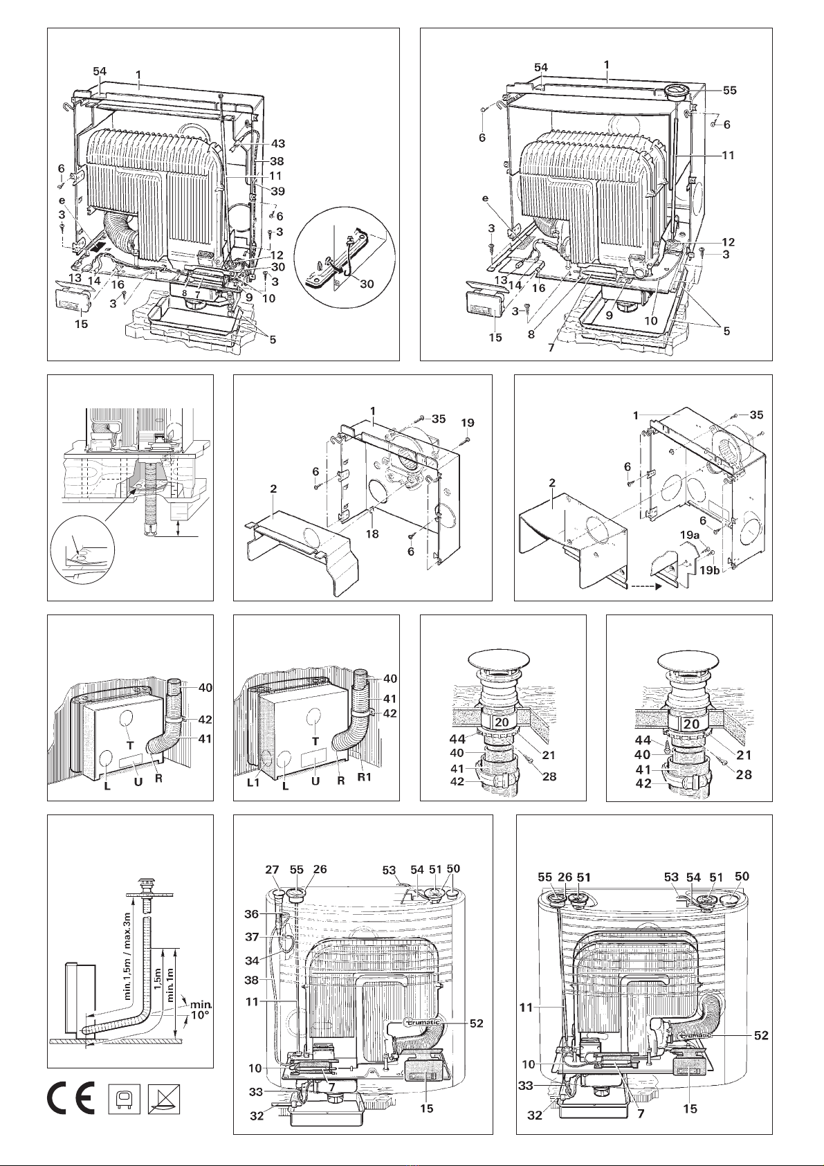
4. Anhand der Einbauschablone prüfen, ob der Bodenausschnitt
(S 3002 (P): 205 x 100 mm, S 5002: 235 x 230 mm) für die
Verbrennungsluftansaugung rechts oder links unterhalb des
Gerätes erfolgen soll (Bild A zeigt Rechtseinbau, Bild G Link-
seinbau). Die Verbrennungsluftansaugung darf nicht im
Spritzbereich der Räder liegen, ansonsten Spritzschutz
anbringen.
Unterhalb des Gerätes dürfen sich keine wärme-
empfindlichen Materialien befinden (Teppichboden
ausschneiden). Bei PVC-Böden kann eine Verfärbung durch
die Erwärmung des Heizungssockels auftreten. Auch am Fahr-
zeugunterboden im näheren Bereich der Verbrennungsluftan-
saugung dürfen sich keine brennbaren / wärmeempfindlichen
Materialien befinden, bzw. müssen diese vor thermischen Ein-
flüssen geschützt werden (z. B. durch ein Abschirmblech).

4
Heizungseinbau
Trumatic S 3002 P
1. Bild A: Heizgerät in den Bodenausschnitt stellen. Ther-
mostatfühler mit Abschirmblech (7) in Schlitz (8) einstecken
und bis zum hörbaren Einrasten unter die Befestigungslasche
(9) schieben (Bild A zeigt Rechtseinbau, Bild G Linkseinbau).
Der Thermostatfühler (7) muss immer vorne an der Hei-
zung (Raumseite) montiert sein. Thermostatfühler (7)
und Kapillarrohr (10) dürfen auf keinen Fall am Wärmetau-
scher bzw. an der Heizungsverkleidung anliegen!
2. Bild C: Heizung an die hinteren Distanzwinkel (18) im Ein-
baukasten heranschieben.
3. Bild A: Heizung mit den 5 Schrauben (3) an den vorgesto-
chenen Punkten in den Ecken und vorne mittig befestigen.
Eventuell Bodenkonstruktion durch Leisten verstärken.
4. Bild A: Die Massefeder (30) aus der Transportsicherung
herausdrücken, damit diese am Einbaukasten anliegt (sonst
funktioniert die Zündung nicht).
5. Bild A: Druckstange mit Ösenfeder (11) in das Zündsiche-
rungsventil (12) einstecken.
Zündkabel (38) auf der Seite der Druckstange in den 3 Haltela-
schen (39) des Einbaukastens befestigen.
Trumatic S 3002
1. Bild A: Heizgerät in den Bodenausschnitt stellen. Ther-
mostatfühler mit Abschirmblech (7) in Schlitz (8) einstecken
und bis zum hörbaren Einrasten unter die Befestigungslasche
(9) schieben (Bild A zeigt Rechtseinbau, Bild G Linkseinbau).
Der Thermostatfühler (7) und der Zündautomat (15)
müssen sich immer vorne an der Heizung (Raumseite)
befinden. Thermostatfühler (7) und Kapillarrohr (10) dürfen auf
keinen Fall am Wärmetauscher bzw. an der Heizungsverklei-
dung anliegen!
2. Bild C: Heizung an die hinteren Distanzwinkel (18) im Ein-
baukasten heranschieben.
3. Bild A: Zündautomat (15) aus der Halterung entnehmen.
Heizung mit den 5 Schrauben (3) an den vorgestochenen
Punkten in den Ecken und vorne mittig befestigen. Eventuell
Bodenkonstruktion durch Leisten verstärken.
4. Am Zündautomat (15) den korrekten Sitz der Steckan-
schlüsse (13 + 14) überprüfen. Dann Zündautomat (15) bis
zum Anschlag in die Laschen (16) einschieben (Bild A zeigt
Rechtseinbau, Bild G Linkseinbau).
5. Bild A: Druckstange mit Ösenfeder (11) in das Zündsiche-
rungsventil (12) einstecken.
Trumatic S 5002
Für den Einbau einer Heizung Trumatic S 5002 ab
Baujahr 05/98 im Tausch gegen eine Heizung Trumatic
S 5002 bis Baujahr 05/98 liefert Truma einen zusätzlich benöti-
gten Montageblendensatz (bitte fragen Sie Ihren Händler).
1. Bild A: Heizgerät in den Bodenausschnitt stellen. Ther-
mostatfühler mit Abschirmblech (7) in Lasche (8) einstecken
und mit Schraube (9) befestigen (Bild A zeigt Rechtseinbau,
Bild G Linkseinbau).
Thermostatfühler (7) und Zündautomat (15) müssen
sich immer vorne an der Heizung (Raumseite) befinden.
Thermostatfühler (7) und Kapillarrohr (10) dürfen auf keinen
Fall am Wärmetauscher bzw. an der Heizungsverkleidung
anliegen!
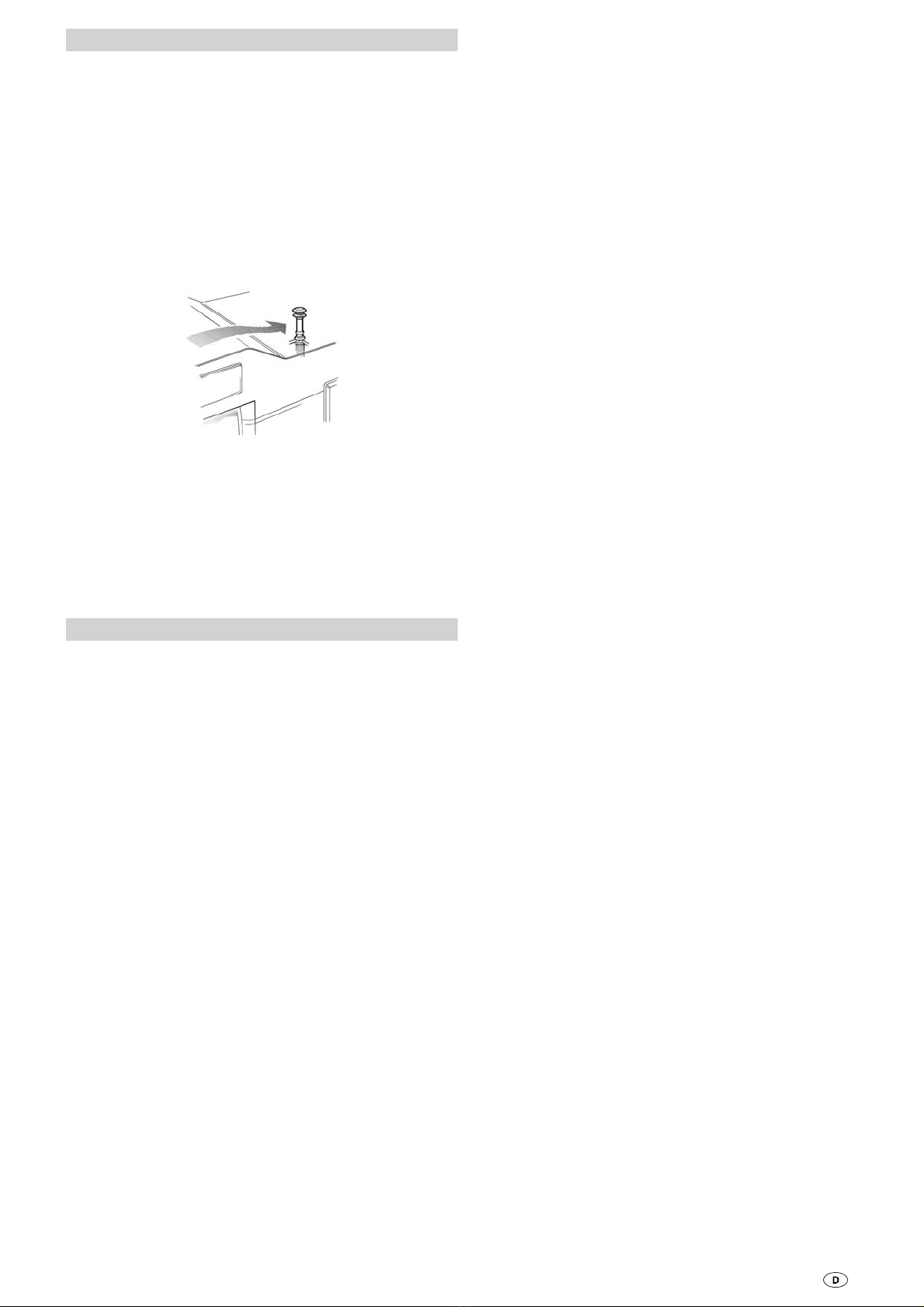
Bild B: Wird die Heizung auf einen Sockel, Doppelboden
oder Ähnlichem montiert, muss zwingend die Ansaugver-
längerung (Art.-Nr. 30030-04800, Länge 50 cm) verwendet
werden. Die Ansaugverlängerung muss frei im Luftstrom ca.
5 bis 10 cm unter der tiefsten Stelle des Fahrzeuges heraus-
ragen (Länge bei Bedarf kürzen). Für die Trumatic S 5002 sind
2 Ansaugverlängerungen erforderlich.
Der Sockel oder Doppelboden muss dicht gegenüber
dem Fahrzeuginnenraum sein und wegen der Gefahr
eines Zurückbrennens unter ungünstigen Windverhältnis-
sen aus nicht brennbarem Material gefertigt oder innen mit
Blech verkleidet werden. Zur Vermeidung der Ansamm-
lung von unverbranntem Gas, muss der Sockel eine Ent-
lüftung von min. 2 cm² an tiefster Stelle haben oder nach
unten offen sein.
5. Abgasleitungen und Kamine müssen so installiert
sein, dass das Eindringen von Abgas in das Fahrzeug-
innere nicht möglich ist.
Um eine gleichmäßige und rasche Warmluftverteilung
sowie eine Absenkung der Oberflächentemperaturen am
Heizgerät sicherzustellen, empfehlen wir den Einbau einer
Trumavent Warmluftanlage.
Auf Wunsch ist die Heizung Trumatic S 5002 auch mit
einem speziellen Einbaukasten für zwei Trumavent Ge-
bläse lieferbar.
Vorarbeiten und Einbaukasten
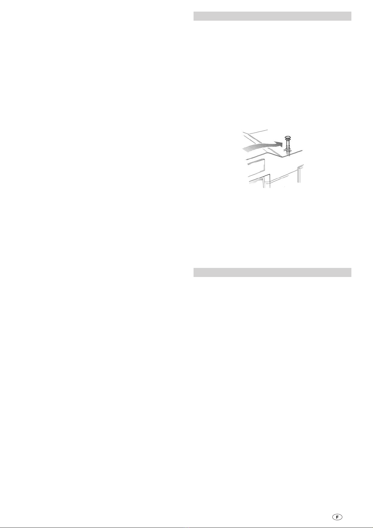
1. Bodenschablone im Einbauausschnitt mit Reißnägeln be-
festigen, der Pfeil muss genau auf die Vorderkante des Aus-
schnittes zeigen (R = Rechtseinbau, L = Linkseinbau).
2. Bodenausschnitt aussägen und die 5 Punkte für die Befes-
tigungsschrauben vorstechen. Die Maße müssen genau
eingehalten werden!
3. Bild A: Rahmenhälften (5) in den Bodenausschnitt ein-
legen, nach außen drücken und festschrauben (evtl. vorher
durch Aufbiegen der Schenkel vorspannen, damit der Rahmen
gut sitzt).
4. Bild D: Am Einbaukasten-Außenteil die vorgestanzten
Durchbrüche für das Abgasrohr ausbrechen (R = Rechts-
einbau, L = Linkseinbau). Bei geringer Einbautiefe kann bei
der Heizung S 5002 das Abgasrohr auch seitlich durchgeführt
werden (R1 oder L1).
Bei Einbau des Spezialrohres für Innen-Gasanschluss (siehe
„Gasanschluss“) beide Durchführungen ausbrechen.
Falls ein Trumavent Gebläse und/oder die Elektro-Zusatz-
heizung Truma Ultraheat montiert wird, die entsprechend
vorgestanzten Deckel (T) bzw. (U) entfernen und diese ent-
sprechend der jeweils beiliegenden Einbauanweisung am Ein-
baukasten vormontieren.
5. Bild C: Einbaukasten-Außenteil (1) und Innenteil (2) aufein-
anderlegen und mit 5 Blechschrauben (19) befestigen.
Bei der Heizung S 5002 müssen die Schrauben (19a) für
Rechtseinbau und die Schrauben (19b) für Linkseinbau
verwendet werden.
Wird kein Trumavent Gebläse angebaut, die 3 Bestigungs-
schrauben (35) trotzdem fest eindrehen.
6. Den vormontierten Einbaukasten im Einbau-Ausschnitt mit
6 Schrauben (6) jeweils schräg nach außen verschrauben.

5
2. Bild A: Zündautomat (15) aus der Halterung entnehmen.
Heizung mit den 5 Schrauben (3) an den vorgestochenen
Punkten in den Ecken und vorne mittig befestigen. Eventuell
Bodenkonstruktion durch Leisten verstärken.
3. Am Zündautomat (15) den korrekten Sitz der Steckan-
schlüsse (13 + 14) überprüfen. Dann Zündautomat (15) bis
zum Anschlag in die Laschen (16) einschieben (Bild A zeigt
Rechtseinbau, Bild G Linkseinbau).
4. Bild A: Druckstange mit Ösenfeder (11) in das Zündsi-
cherungsventil (12) einstecken. Bedienungsgriff (55) auf die
Druckstange (11) so aufstecken, dass der Pfeil zur „0“ Stel-
lung (Heizungsmitte) zeigt.
Abgaskamin
Die Heizung ist nur mit Dachkamin zulässig. Dieser darf
nur senkrecht oder mit maximal 15 Grad Neigung einge-
baut werden!
Bild F: Dachkamin so platzieren, dass von der Heizung zum
Kamin eine direkte, auf ganzer Länge steigende Rohrverle-
gung (min. 1,5 m, max. 3 m) möglich ist. Bei einer Rohrlänge
von 1,5 m muss eine Mindesthöhe von 1 m erreicht sein. Die
weitere Rohrverlegung zum Dachkamin muss nahezu senk-
recht erfolgen.
Trumatic S 3002 (P)
Bild E: Öffnung von Ø 60 mm in einem Mittelabstand von
min. 55 mm zu seitlichen Wänden ausschneiden.
Trumatic S 5002
1. Bild E: Öffnung von Ø 70 mm in einem Mittelabstand von
min. 60 mm zu seitlichen Wänden ausschneiden.
2. Bild E: Bei doppelschaligen Dächern den Hohlraum mit
Holz ausfüttern oder einen kreisförmig eingerollten Blechstrei-
fen (20) von etwa 220 mm Länge und 1 mm Stärke einschie-
ben, um das Dach so zu versteifen, dass es beim Anziehen
der Verschraubung nicht verformt wird und regendicht bleibt.
3. Bild E: Kamin von oben durch das Dach stecken und innen
mit Schraubring (21) festziehen. Anschließend Schraubring (21)
mit der Schraube (44) sichern.
Abdichtung erfolgt mit beigelegter Gummidichtung ohne wei-
tere Dichtmittel.
Abgasführung
Für die Trumatic S darf nur das Truma Edelstahl-Abgasrohr
AE 3 bzw. AE 5 mit Truma Überrohr ÜR bzw. ÜR 5 (APP) ver-
wendet werden, da die Geräte nur in Verbindung mit diesen
Rohren geprüft und zugelassen sind.
Länge des Abgasrohres min. 1,5 m, max. 3 m!
Eine erhebliche Montage-Erleichterung für das Biegen des
Edelstahlrohres und das Aufziehen des O-Ringes bringt die
Verwendung des Biege-Boys (Art.-Nr. 30030-33000).
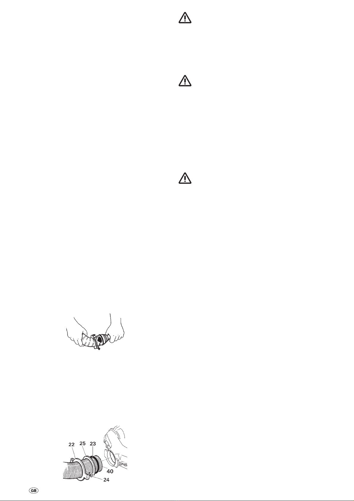
1. Abgasrohr an die Heizung anschließen:
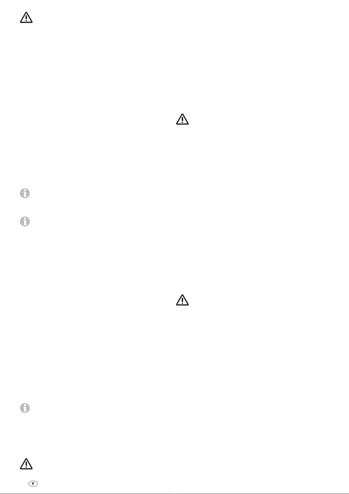
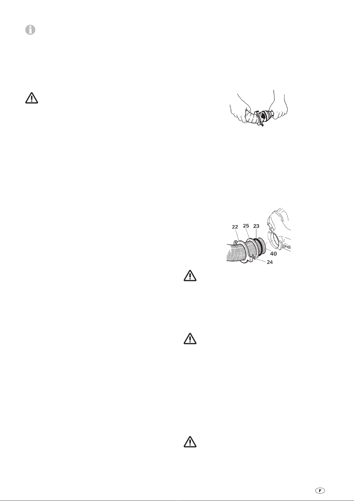
Dichtplatte (22) etwa 3 cm auf das Abgasrohr schieben (Kralle
zeigt zum Abgasstutzen der Heizung). Druckring (25) aufschie-
ben. O-Ring (23) durch Ausweiten vorsichtig über die Rohr-
schnittkante führen und Abgasrohr bis auf Anschlag in den
Abgasstutzen stecken.
O-Ring, Druckring und Dichtplatte an den Abgasstutzen her-
anschieben. Dichtplatte (22) durch Drehen einhängen und mit
Schraube (24) fest anziehen.
Nach jeder Demontage muss ein neuer O-Ring (23)
montiert werden.
2. Überrohr (41) auf das Abgasrohr schieben (muss vom Kamin
bis zur Rückwand des Einbaukastens reichen, siehe Bild E + D).
3. Bild D + E: Rohre an der Wand mit wenig Krümmungen
hochführen. Abgasrohr (40) bis Anschlag in den Kamin ein-
schieben und mit Blechschraube (28) sichern.
Abgasrohr (40) mit Überrohr (41) muss auf ganzer
Länge steigend und mit mehreren Schellen (42) fest
und dauerhaft montiert sein, da sich sonst ein Wasser-
sack bilden kann, welcher den freien Abzug der Abgase
verhindert.
Gasanschluss
Bild A (e): Der Betriebsdruck der Gasversorgung 30 mbar
muss mit dem Betriebsdruck des Gerätes (siehe Typenschild)
übereinstimmen.
Bild G: Die Gaszuleitung (32) muss mit Schneidringverschrau-
bung am Stutzen (33), 8 mm Außendurchmesser, angeschlos-
sen werden.
Der Gasanschlussstutzen an der Heizung darf
nicht verbogen werden! Beim Festziehen des An-
schlussnippels diesen sorgfältig mit einem Schlüssel
gegenhalten!
Die Rohrverlegung ist so zu wählen, dass für Service-Arbeiten
die Heizung wieder ausgebaut werden kann.
Vor dem Anschluss an die Heizung sicherstellen, dass die
Gasleitungen frei von Schmutz, Spänen und Ähnlichem sind!
Auf Wunsch steht ein Spezialrohr für Innen-Gasanschluss
zur Verfügung, das mittels Winkelverschraubung am Gas-
anschlussstutzen (33) verschraubt wird.
Die Gasanlage muss den technischen und administrativen Be-
stimmungen des jeweiligen Verwendungslandes entsprechen
(in Europa z. B. EN 1949 für Fahrzeuge).
Nationale Vorschriften und Regelungen (in Deutschland z. B.
das DVGW-Arbeitsblatt G 607 für Fahrzeuge) müssen beach-
tet werden.
Heizungsverkleidung
1. Bild G: Griffbuchse (26), falls vorhanden Piezo-Druckzün-
der (27) und das integrierte Bedienteil (51) für das Trumavent
Gebläse TEB in die Aussparungen eindrücken (Rechts- oder
Linkseinbau beachten!). Freie Aussparungen mit Verschluss-
deckel (50) verschließen.
6
Nur Trumatic S 3002 P
Massekabel (34) am Druckzünder (27) und am Massekontakt
(37) der Verkleidung anstecken.
2. Typenschild (52) in die Sichtfenster-Aussparung eindrücken
(Rechts- oder Links-einbau beachten!).
3. Bei integriertem Bedienteil (51) das Verbindungskabel (53)
des Trumavent Gebläses TEB am Bedienteil anstecken. Lasche
(54) am Einbaukasten nach hinten umbiegen und Verbin-
dungskabel (53) durchführen.
Nur Trumatic S 3002 P
Flachstecker des Zündkabels (38) auf den Anschluss (36) am
Druckzünder (27) schieben und Isolierung (43) aufschieben
(siehe Bild A).
Trumatic S 3002 (P)
4. Verkleidung auf die unteren Haltelaschen stellen. Druck-
stange (11) von unten in die Griffbuchse (26) einführen und
Verkleidung oben einrasten lassen. Bedienungsgriff (55) von
oben so auf die Druckstange (11) aufstecken, dass der Pfeil
zur „0“-Stellung zeigt.
Trumatic S 5002
4. Verkleidung auf die unteren Haltelaschen stellen. Druck-
stange (11) mit Bedienungsgriff (55) von unten in die Griff-
buchse (26) einführen und Verkleidung oben einrasten lassen.
Verkleidung Kaminfeuer
Elektrischer Anschluss 12 V
Elektrische Leitungen, Schalt- und Steuergeräte für Heiz-
geräte müssen im Fahrzeug so angeordnet sein, dass ihre
einwandfreie Funktion unter normalen Betriebsbedingungen
nicht beeinträchtigt werden kann. Alle nach außen führenden
Leitungen müssen am Durchbruch spritzwasserdicht verlegt
sein.
Beiliegendes Kabel (1,5 m) am abgesicherten Bordnetz (Zen-
tralelektrik 5 A) anschließen. Auf Polarität muss nicht geachtet
werden.
An die Zuleitung dürfen keine weiteren Verbraucher ange-
schlossen werden!
Bei Verwendung von Netz- bzw. Stromversorgungsgeräten
beachten, dass diese eine geregelte Ausgangsspannung
zwischen 11 V und 15 V liefern und die Wechselspannungs-
welligkeit < 1,2 Vss beträgt. Für die unterschiedlichen Anwen-
dungsfälle empfehlen wir die Ladeautomaten von Truma. Bitte
fragen Sie Ihren Händler. Andere Ladegeräte nur mit einer
12 V-Batterie als Puffer verwenden.
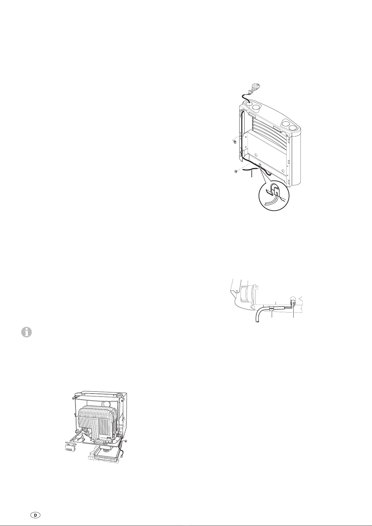
Die Zuleitung 12 V am Boden nach hinten durchführen und
mittels der beiliegenden Klammer am Heizungssockel fixieren.
+ 12 V
Bedienteil
Die Verkleidung Kaminfeuer ist für den Standard-Rechtseinbau
ausgelegt. Für den Linkseinbau muss an der Verkleidung Ka-
minfeuer das Bedienteil auf die rechte Seite versetzt werden.
Hierzu am Bedienteil das Kabel abziehen, die beiden Rastna-
sen zusammendrücken und das Bedienteil herausnehmen.
Bedienteil in die rechte Seite eindrücken. Anschließend das
Kabel entsprechend der Abbildung an der rechten Verklei-
dungsseite zum Bedienteil verlegen.
12 V
Montage der Verkleidung
Zuleitung 12 V an die Elektronik anstecken (Stecker so aufste-
cken, dass die beiden Steckerleitungen nach unten gehen).
Zuleitung in die Klammer (d) am Verkleidungsboden einhän-
gen. Verkleidung auf die unteren Haltelaschen stellen. Druck-
stange (11) mit Bedienungsgriff (55) von unten in die Griff-
buchse (26) einführen und Verkleidung oben einrasten lassen.
d12 V
Funktionsprüfung
Nach dem Einbau muss die Dichtigkeit der Gaszuleitung
nach der Druckabfallmethode geprüft werden. Eine Prüf-
bescheinigung (in Deutschland z. B. gemäß DVGW-Arbeits-
blatt G 607) ist auszustellen.
Anschließend gemäß der Gebrauchsanweisung sämtliche
Funktionen des Gerätes prüfen.
Die Gebrauchsanweisung mit ausgefüllter Garantiekarte ist
dem Fahrzeughalter auszuhändigen.
Warnhinweise
Der dem Gerät beiliegende gelbe Aufkleber mit den Warnhin-
weisen ist durch den Einbauer bzw. Fahrzeughalter an einer
für jeden Benutzer gut sichtbaren Stelle im Fahrzeug (z. B. an
der Kleiderschranktür) anzubringen! Aufkleber ggf. bei Truma
anfordern.
7
Besondere Einbauhinweise
Die Heizung ist nur mit Dachkamin zulässig. Bei Betrieb
der Heizung während der Fahrt ist unbedingt der Ka-
minaufsatz T3 (Art.-Nr. 30700-03) erforderlich, der frei im
Luftstrom liegen muss. Gegebenenfalls ist zusätzlich eine
Kaminverlängerung AKV (Art.-Nr. 30010-20800) einzubauen.
Diese muss mit einer Schraube gesichert werden.
Der Reisemobilhersteller bzw. Heizungseinbauer muss die
Kombination von Kaminaufsatz und ggf. Verlängerungen bei
den einzelnen Auslieferungszuständen der Fahrzeuge durch
Versuchsfahrten ermitteln und ggf. mit Truma abstimmen. Ab-
hängig vom Fahrzeugtyp und von den Dachaufbauten kann der
Kaminaufsatz T1 (Art.-Nr. 30700-01) oder T2 (Art.-Nr. 30700-02)
erforderlich sein.
Dachaufbauten sowie verstautes Gepäck im Umkreis des
Abgaskamins stören die Funktion der Heizung, insbesondere
während der Fahrt. Die Flamme kann dadurch zurück-
brennen und Schäden an der Heizung und am Fahrzeug
verursachen. In diesen Fällen müssen weitere Kaminverlän-
gerungen verwendet werden, so dass der Kaminaufsatz min-
destens 10 cm über die Gegenstände hinausragt. Bei Nicht-
beachtung dieser Hinweise besteht kein Garantieanspruch für
entstandene Schäden an der Heizung und am Fahrzeug.
Allgemeine Hinweise
1. Wird der Fahrzeugboden mit Unterbodenschutz versehen,
müssen alle unter dem Wagen befindlichen Heizungsteile
abgedeckt werden, damit der entstehende Spritznebel nicht
zu Funktionsstörungen der Heizungsanlage führt. Nach Ab-
schluss der Arbeiten Abdeckungen wieder entfernen.
2. Falls beim Einbau Frischluft-Ansaugöffnungen ange-
bracht werden, müssen diese so angeordnet sein, dass keine
verunreinigte Luft (Abgase, Benzin- oder Öldämpfe) ins Fahr-
zeuginnere gelangen kann.
3. In Sonderfällen kann es zum Eindringen von Staub usw.
kommen. Für diese Fälle empfehlen wir den Einbau eines
Dichtungssatzes
S 3002 (P): Art.-Nr. 30030-89800
S 5002: Art.-Nr. 30050-32700.

8
Installation instructions
Installation and repair jobs on the heater are only to be
carried out by an expert. Read and follow the installation
instructions carefully prior to starting any work!
Non-compliance with installation instructions or
incorrect installation can result in endangerment
of persons and property.
Intended use
This heater was built for installing in caravans and other trail-
ers. The S 3002 (P) heater is also suitable for installing in mo-
tor homes. It is not approved for installation in boats. Other
forms of use are also possible after consultation with Truma.
Approval
Directive 2004/78/EC stipulates that a safety shut-off device
is required if motor homes are being heated while driving.
The Truma gas pressure control systems SecuMotion /
MonoControl CS satisfy these requirements.
The installation of a safety shut-off device, such as e.g. the gas
pressure control system Truma SecuMotion / MonoControl CS
with the correct gas installation configuration, means that the
operation of a type-approved liquid gas heating system when
the vehicle is on the move is approved throughout Europe in
accordance with the EC Directive 2001/56/EC.
The safety shut-off device is also recommended for safety
reasons if caravans are being heated while driving.
S 3002 (P)
The S 3002 (P) heater is approved for installation in motor
vehicles for transporting passengers (vehicle class M1 motor
homes) that have no more than 8 seats (excluding the driver’s
seat) and for installation in trailers (vehicle class O caravans).
The equipment must not be installed in busses (vehicle
classes M2 and M3) or vehicles for transporting hazard-
ous goods.
For installation in special-purpose vehicles, the regulations ap-
plicable in each case must be observed.
S 5002
The S 5002 heater is approved for installation in trailers (vehi-
cle class O caravans).
The equipment must not be installed in motor homes
(vehicle class M1), busses (vehicle classes M2 and M3)
or vehicles for transporting hazardous goods.
For installation in special-purpose vehicles, the regulations ap-
plicable in each case must be observed.
Declaration of conformity
The Trumatic S has been tested by the DVGW and complies
with the gas equipment directive (90/396/EEC) and the other
applicable EC directives. The product ID No. for EU countries is
S 3002 (P): CE-0085AP0325
S 5002: CE-0085AP0326
The heater complies with heater directive 2001/56/EC and
annexes 2004/78/EC and 2006/119/EC and bears the
type approval number
S 3002 (P): e1 00 0140
S 5002: e1 00 0141
The heating system satisfies the directive relating to the
radio interference of vehicles 2004/104/EC, 2005/83/EC and
2006/28/EC and bears the type approval number:
e1 03 2603
The heating system satisfies the EMC directive 2004/108/EC
and the End-Of-Life Vehicle directive 2000/53/EC.
Regulations
Guarantee claims, warranty claims and acceptance of liability
will be ruled out in the event of the following:
– modifications to the unit (including accessories),
– modifications to the exhaust duct and the cowl,
– failure to use original Truma parts as replacement parts
and accessories,
– failure to follow the installation and operating instructions.
It also becomes illegal to use the appliance, and in some
countries this even makes it illegal to use the vehicle.
The year when the equipment was first taken into oper-
ation must be indicated with a check on the type plate.
Installation in vehicles must accord with the technical and
administrative provisions of the individual country of use (e.g.
EN 1949). National specifications and regulations (in Germany,
for example, DVGW Worksheet G 607) must be respected.
In other countries always observe the respectively valid
regulations.
More information on the regulations in the relevant destina-
tion countries can be requested from our foreign representa-
tives (see Truma Service Booklet or www.truma.com).
The combustion air must not be taken from the vehicle
interior. The combustion air must always be obtained
from the outside.
Please pay attention to the “Special installation instructions”
when installing the equipment in motor homes.
Choice of location
1. The driver must not be able to come into contact with the
heater when sitting in his seat. The heater must not be in-
stalled directly behind the driver’s seat.
2. Always install the appliance and its exhaust gas duct in
such a way that it is easily accessible for service work at all
times and can be removed and installed easily.
3. As a rule, the heater should be installed inside the wardrobe
in the vehicle.
Installation cut-out
S 3002 (P): 480 x 480 mm
S 5002: 510 mm wide, 522 mm high.
For satisfactory operation of the heater it is important that the
heater base and bottom edge of the installation box are as-
sembled on one level so that the control knob is flush with the
casing.
4. Using the installation template, check whether the floor cut-
out section (S 3002 (P) 205 x 100 mm, S 5002: 235 x 230 mm)
for the combustion air intake is to be on the right or on the
left, under the appliance (fig. A shows right-handed instal-
lation, fig. G left-handed installation). The combustion air
intake must not be subjected to wheel spray, otherwise
fit a spray guard.
There should be no heat-sensitive materials under
the appliance (cut away carpeting). In the case of PVC
flooring, the heating of the heater base may cause some dis-
coloration. Never allow flammable / heat sensitive material to
be near the combustion-air suction, not even in close proximi-
ty to the vehicle underbody. Alternatively, these must be pro-
tected from thermal influences (e.g. by using an air shield).
Fig. B: If the heater is installed on a plinth, false floor or
the like, the intake extension (part no. 30030-04800, length
50 cm) must be used. The intake extension must be freely
suspended in the air flow approximately 5 to 10 cm below the
lowest point of the vehicle (shorten if necessary). Two intake
extensions are required for the Trumatic S 5002.

9
2. Fig. C: Slide heater to the rear spacer brackets (18) in the
installation box.
3. Fig. A: Fasten heater with 5 screws (3) to the pre-drilled
points in the corners and at the front in the center. If neces-
sary, reinforce the floor structure with battens.
4. Fig. A: Press ground spring (30) out of the transportation
safety device so that it rests against the installation box (other-
wise the ignition will not work).
5. Fig. A: Insert push rod with eye spring (11) into the ignition
safety valve (12).
Fasten ignition cable (38) on the side of the push rod in the
3 retaining straps (39) of the installation box.
Trumatic S 3002
1. Fig. A: Place the heater unit in the floor opening. Plug the
thermostat probe with the screening plate (7) in the slot (8)
and slide it under the attachment piece (9) until you hear it
engage (fig. A shows right-handed installation, fig. G shows
left-hand installation).
The thermostat probe (7) and automatic ignitor (15)
must always be at the front of the heater (facing the
room). The thermostat probe (7) and the capillary tube (10)
must never touch the heat exchanger or the heater casing!
2. Fig C: Slide heater to the rear spacer brackets (18) in the
installation box.
3. Fig A: Remove automatic ignitor (15) from its mount. Fas-
ten heater with 5 screws (3) to the pre-drilled points in the
corners and at the front in the center. If necessary, reinforce
the floor structure with battens.
4. Check the automatic ignition device (15) to ensure that the
plug-in connections (13 + 14) are mounted properly. Then
push the automatic ignition device (15) into the link plates (16)
as far as the stop (fig. A shows right-hand installation, fig. G
shows left-hand installation).
5. Fig. A: Insert push rod with eye spring (11) into the ignition
safety valve (12).
Trumatic S 5002
When installing a Trumatic S 5002 heater starting from
date of manufacture 05/98 as a replacement for a
Trumatic S 5002 heater up to date of manufacture 05/98,
Truma supplies an additionally required assembly-cover set
(please ask your dealer).
1. Fig. A: Place the heater unit in the floor opening. Insert the
thermostat probe (7) with screening plate into strap (8) and
fasten it with self-tapping screw (9). (Fig. A shows right-hand
installation, fig. G shows left-hand installation.)
Thermostat probe (7) and automatic ignitor (15) must al-
ways be at the front of the heater (facing the room).
Thermostat probe (7) and capillary tube (10) must never be al-
lowed to touch the heat exchanger or heater casing!
2. Fig A: Remove automatic ignitor (15) from its holder.
Fasten the heater by means of the 5 screws (3 – holes are
pre-punched in the corners and front centre). If necessary, re-
inforce the floor structure with battens.
3. Check the automatic ignition device (15) to ensure that the
plug-in connections (13 + 14) are mounted properly. Then
push the automatic ignition device (15) into the link plates (16)
as far as the stop (fig. A shows right-hand installation, fig. G
shows left-hand installation).
4. Fig. A: Insert push rod with eye spring (11) into ignition
safety valve (12). Insert control knob (55) onto push rod (11)
so that the arrow points to „0” (heater middle position).
The plinth or false floor must be sealed from the vehi-
cle interior and must be made from a non-flammable
material or lined on the inside with sheet metal because of
the risk of blow-back under unfavourable wind conditions.
To prevent non-burned gas from building up the plinth
must have a vent at least 2 cm² in size at its lowest point,
or must be open at the bottom.
5. Exhaust ducts and cowls must be installed in such
a way that exhaust gas cannot find its way into the
vehicle.
To ensure even and rapid warm air distribution as well as
lower surface temperatures on the heating unit, we rec-
ommend installing a Trumavent warm-air system.
If desired, the Trumatic S 5002 heating system is also
available with a special installation box for two
Trumavent fans.
Preparatory work and installation boxes
1. Secure the template for the floor opening in the cut-out
section by means of thumb tacks, the arrow must point exact-
ly to the front edge of the opening (R = right-hand installation,
L = left-hand installation).
2. Cut the floor opening using a saw and pre-drill 5 holes
for the fixing screws. The exact dimensions must be
observed!
3. Fig. A: Insert half-frames (5) in the floor opening and press
them outwards and screw tight (pretension as needed by
bending the sides upward so that the frame fits firmly).
4. Fig. D: Break out the pre-stamped apertures for the waste
gas pipe on the outer part of the installation box (R = right-
hand installation, L = left-hand installation). If the installation
depth is small, the waste gas pipe can also be conducted
through the side with the S 5002 heating system (R1 or L1).
When installing the special pipe for internal gas connection
(refer to “Gas connection”), break out both apertures.
If a Trumavent fan and / or Truma Ultraheat electrical
supplementary heating are being fitted, remove the pre-
stamped cover (T) or (U) respectively, and fit the units to the
installation box in accordance with the installation instructions
provided in each case.
5. Fig. C: Separate the outer part (1) and inner part (2) of
the installation box, and secure them with 5 sheet metal
screws (19).
For the S 5002 heating system, the screws (19a) must
be used for right-hand installation and the screws (19b)
for left-hand installation.
Firmly screw in the 3 screws (35), even if you are not installing
a Trumavent fan.
6. Place the pre-assembled installation box in the opening and
screw at an angle to the outside using 6 bolts (6) respectively.
Installation of the heater
Trumatic S 3002 P
1. Fig. A: Place the heater unit in the floor opening. Plug the
thermostat probe with the screening plate (7) in the slot (8)
and slide it under the attachment piece (9) until you hear it
engage (fig. A shows right-hand installation, fig. G shows left-
hand installation).
The thermostat probe (7) must always be at the front of
the heater (facing the room). Thermostat probe (7) and
the capillary tube (10) must never touch the heat exchanger or
the heater casing!
10
Exhaust gas cowl
The heater is only approved when used with a roof cowl.
This must be installed vertically or with no more than a
15 degree slope!
Fig. F: Position the roof cowl so that the duct (minimum
length 1.5 m, maximum length 3 m) can be routed direct from
the heater unit, sloping upward all the way to the cowl. A
1.5 metre long duct must reach a height of at least 1 metre.
The remainder of the duct to the roof cowl must be installed
more or less vertically.
Trumatic S 3002 (P)
Fig. E: Cut out an opening with a Ø of 60 mm at a centre dis-
tance of at least 55 mm from the side walls.
Trumatic S 5002
1. Fig. E: Cut out an opening with a Ø of 70 mm at a centre
distance of at least 60 mm from the side walls.
2 Fig. E: In the case of a double-skin roof, line the cavity with
wood or slide in a rolled circular sheet metal strip (20) of about
220 mm in length and 1 mm in thickness, to stiffen the roof so
that when the screws are tightened it does not warp and stays
weatherproof.
3. Fig. E: Push the cowl through the roof from above and
fasten it on the inside with screw ring (21). Next, secure the
screw ring (21) with a screw (44).
Use the enclosed rubber sealing ring without further sealing
materials.
Exhaust duct
For the Trumatic S, only the Truma stainless-steel waste gas
pipe AE 3 or AE 5 with the Truma pipe sheath UR or UR 5 (APP)
may be used, since the devices have only been tested and ap-
proved in conjunction with these pipes.
Length of exhaust duct: min. 1.5 m, max. 3 m!
Fitting and bending the stainless steel duct and stretch-
ing open the O-ring are made considerably easier by using
“Biege-Boy“ (part no. 30030-33000).
1. Connecting the exhaust duct to the heater:
Slide sealing plate (22) about 3 cm onto the exhaust duct
(with the claw pointing towards the heater exhaust outlet).
Slide on pressure ring (25). Stretch open O-Ring (23) and
carefully pass it over the cut edge of the duct. Then plug the
exhaust duct into the exhaust outlet as far as the stop.
Slide the O-ring, pressure ring and sealing plate to the exhaust
outlet. Twist on sealing plate (22) and fasten it securely by
tightening screw (24).
A new O-ring (23) must be fitted each time the
exhaust duct is dismantled.
2. Slide insulating duct (41) onto the exhaust duct (it must
reach from the cowl to the rear wall of the installation box,
refer to fig. E + D).
3. Fig. D + E: Take the ducting up the wall with as few bends
as possible. Slide exhaust gas duct (40) into the cowl as far as
the stop and secure with self-tapping screw (28).
The flue gas pipe (40) with insulating duct (41)
must be ascending along its entire length and se-
curely and permanently installed using several clamps
(42), since otherwise a water pocket may form that will
prevent the flue gas from exiting freely.
Gas connection
Fig. A (e): The gas supply’s operating pressure (30 mbar)
must be the same as the unit´s operating pressure (see type
plate).
Fig. G: The gas supply pipe (32) must be connected using a
cutting ring screw fitting with an outer diameter of 8 mm at
the connecting piece (33).
The gas connection fitting on the heating appli-
ance must not be bent! When tightening the connec-
tion nipple, hold it carefully in place with a second wrench!
Route the ducting in such a way that the heater can be re-
moved for servicing work.
Make sure the gas lines are free of dirt, chips and such prior
to connecting!
A special duct for internal gas connection is available on re-
quest. It is screwed onto gas connection fitting (33) with an
elbow.
The gas system must accord with the technical and adminis-
trative provisions of the individual country of use (in Europe,
for example, EN 1949 for motor vehicles).
National regulations and rulings (in Germany, for example,
the DVGW worksheet G 607 for motor vehicles) must be
respected.
Heater casing
1. Fig. G: Push the handle connector (26), the piezo pressure
igniter (27) if applicable, and the integrated operating element
(51) for the Trumavent TEB fan into the cut-outs (take care to
respect right-hand or left-hand installation!). Close off any un-
occupied cut-outs with the closure cover (50).
For Trumatic S 3002 P only
Plug the earthing cable (34) to the pressure igniter (27) and
the earth contact (37) on the casing.
2. Press type plate (52) into the observation window opening
(note right-handed or left-handed installation!).
3. With integrated control panel (51) plug connecting cable
(53) of the Trumavent fan TEB into the control panel. Bend
back strap (54) on the installation box and insert connecting
cable (53).
For Trumatic S 3002 P only
Slide flat connector of ignition cable (38) on the connection
(36) on the piezo ignitor (27) and slide on insulation (43 – refer
to fig. A).

11
Trumatic S 3002 (P)
4. Place the casing onto the lower retaining shackles. Guide
the pressure rod (11) from below into the handle connector
(26) and engage the casing at the top. Push the operating
handle (55) from above onto the pressure bar (11) in such a
way that the arrow points to the “0“ position.
Trumatic S 5002
4. Place the casing onto the lower retaining shackles. Guide
the pressure rod (11) with operating handle (55) from below
into the handle connector (26) and engage the case at the top.
Front case with flame effect
Electrical connection 12 V
Electric cables, switching units and control units for heaters
must be arranged in the vehicle in such a way that their satis-
factory operation cannot be adversely affected under normal
operating conditions. All cables leading to the outside must be
splash proof at the leadthrough opening.
Connect provided cable (1.5 m) to fuse-protected on-board
power supply (5 A central electrical system). The polarity is
not important.
No other consumers must be connected to the supply line!
When power packs or power supply units are being
used, note that the output voltage is between 11 V and
15 V and the alternating current ripple is < 1.2 Vpp. We rec-
ommend the automatic chargers from Truma for the different
applications. Please ask your dealer. Other chargers may be
used only with a 12 V battery as a buffer.
Route 12 V supply line along the floor towards the rear and at-
tach to the heater pedestal using the provided clip.
+ 12 V
Control panel
The front case with flame effect is designed for standard right-
hand installation. The control panel must be moved to the
right-hand side of the front case with flame effect if left-hand
installation is required.
To do this, detach cable from control panel, push both catches
together and remove control panel. Push control unit into
right-hand side. Then route cable along right-hand side of
front case to control panel as shown in figure.
12 V
Fitting the front case
Connect 12 V supply line to electronic system (connect plug
so that both plug wires are routed downwards). Engage sup-
ply line in clip (d) at bottom of front case. Place the casing
onto the lower retaining shackles. Guide the pressure rod (11)
with operating handle (55) from below into the handle con-
nector (26) and engage the case at the top.
d12 V
Function check
After installation, the sealing tightness of the gas feed
line must be tested in accordance with the pressure
drop method. A test certificate (in Germany, for example, in
accordance with the DVGW operational data sheet G 607) is
to be issued.
Following this inspection, test all functions of the appliance as
specified in the operating instructions.
The operating instructions and completed guarantee card are
to be given to the owner of the vehicle.
Warning information
The installer or vehicle owner must display the yellow sticker
with the warning information, enclosed with the appliance, in
the vehicle so it is clearly visible to all users (e.g. on the ward-
robe door)! Ask Truma to send you a sticker if necessary.

12
Special installation instructions
The heater is only approved when used with a roof
cowl. When the heater is being operated when driving,
cowl top T3 (part no. 30700-00) must be used, and must be
freely suspended in the air flow. A cowl extension AKV (part
no. 30010-20800) must also be installed if necessary. This
must be secured with a screw.
The camper manufacturer or heater installer must perform
test drives to determine the combination of flue top and ex-
tensions (if required) for the individual as-delivered vehicle
configurations and consult Truma if necessary. Depending on
the vehicle model and the equipment installed on the roof,
flue top T1 (part no. 30700-01) or T2 (part no. 30700-02) may
be required.
Roof extensions and luggage stowed in the vicinity of the
exhaust cowl impede the operation of the heater, especially
when the vehicle is moving. The flame may flash back,
causing damage to the heater and vehicle. In this case,
additional cowl extensions must be used so that the top of the
cowl projects at least 10 cm above any objects. Failure to ob-
serve this will result in the refusal of any guarantee claim for
resulting damage to the heater and vehicle.
General instructions
1. If the vehicle floor is given a body underseal, all parts of
the heater located under the vehicle must be covered up so
that the underseal spray does not impede the operation of the
heater system. The covers must be removed again when the
work is finished.
2. If fresh air intake vents are installed they must be posi-
tioned so that air which has been polluted (such as by exhaust
gases, petrol fumes or oil vapour) cannot find its way into the
vehicle.
3. In exceptional cases dust penetration etc. may occur.
For these cases we recommend installing a sealing kit
S 3002 (P): part no. 30030-89800
S 5002: part no. 30050-32700.

13
Instructions de montage
Le montage et les réparations du chauffage ne doivent
être effectués que par un spécialiste. Avant de commen-
cer les travaux, étudier attentivement les instructions et s’y
conformer !
Le non-respect des consignes de montage ou un
montage erroné peuvent entraîner des dommages
corporels et matériels.
Utilisation
Ce chauffage a été conçu pour être monté dans des carava-
nes et autres remorques. Le chauffage S 3002 (P) se prête
également au montage dans des camping-cars. Le montage
dans des bateaux n’est pas autorisé. D’autres applications
sont possibles après consultation de Truma.
Homologation
curité pour le chauffage des camping-cars pendant le tra-
jet. Les systèmes de détendeurs gaz Truma SecuMotion /
MonoControl CS remplissent cette exigence.
Grâce à l‘installation d‘un dispositif d‘arrêt de sécurité comme
par ex. un système de régulation de la pression du gaz Truma
SecuMotion / MonoControl CS, avec une installation à gaz
correspondante, l‘utilisation d‘un chauffage homologué au
gaz liquéfié durant la conduite est autorisée en Europe
conformément à la directive CE 2001/56/CE.
Par sécurité, nous recommandons également le dispositif d'arrêt
de sécurité pour le chauffage des caravanes pendant le trajet.
S 3002 (P)
L’appareil de chauffage S 3002 (P) est homologué pour le
montage dans les véhicules à moteur (camping-cars de classe
de véhicule M1) pour le transport de personnes avec 8 places
assises maximum hors siège conducteur ainsi que pour les
remorques (caravanes de classe de véhicule O).
Le montage à l’intérieur d’autobus (classe de véhicule
M2 et M3) ainsi que dans les véhicules de transport de
marchandises dangereuses n’est pas autorisé.
Si l’on monte le chauffage dans des véhicules spéciaux, il faut
observer les règlements applicables dans chaque cas.
S 5002
L’appareil de chauffage S 5002 est homologué pour le mon-
tage dans les remorques (caravanes de classe de véhicule O).
Le montage à l’intérieur de camping-cars (classe de
véhicule M1), d’autobus (classe de véhicule M2 et M3)
ainsi que dans les véhicules de transport de marchandi-
ses dangereuses n’est pas autorisé.
Si l’on monte le chauffage dans des véhicules spéciaux, il faut
observer les règlements applicables dans chaque cas.
Déclaration de conformité
Le Trumatic S a fait l’objet d’un contrôle par la DVGW et ré-
pond à la directive CE sur les appareils à gaz (90/396/CEE) ain-
si qu’aux directives CE également applicables. Pour les pays
de la CE, le numéro d’identification de produit CE a été délivré
S 3002 (P) : CE-0085AP0325
S 5002 : CE-0085AP0326
Le chauffage répond à la directive relative aux appareils de
chauffage 2001/56/CE avec les compléments 2004/78/CE et
2006/119/CE et porte le numéro d‘autorisation de type
S 3002 (P) : e1 00 0140
S 5002 : e1 00 0141
Le chauffage est conforme à la directive concernant l‘antipara-
sitage des moteurs de véhicules 2004/104/CE, 2005/83/CE et
2006/28/CE et porte le numéro d‘homologation : e1 03 2603
Le chauffage est conforme à la directive CEM 2004/108/CE ain-
si qu‘à la directive sur les véhicules hors d‘usage 2000/53/CE.
Prescriptions
Les actions suivantes en particulier invalident les droits à
garantie et entraînent l‘exclusion de toute demande de répara-
tion du préjudice subi :
– modifications apportées à l‘appareil (y compris accessoires) ;
– modifications apportées au guidage des gaz brûlés et à la
cheminée ;
– utilisation de pièces de rechange et accessoires autres que
des pièces originales Truma ;
– non-respect des instructions de montage et du mode
d‘emploi.
En outre, l'autorisation d'utiliser l'appareil est annulée et en-
traîne dans de nombreux pays l'annulation de l'autorisation
pour tout le véhicule.
L‘année de la première mise en marche doit être cochée
sur la plaque signalétique.
Le montage dans les véhicules doit répondre aux disposi-
tions techniques et administratives définies par les pays dans
lesquels les appareils sont utilisés (par ex. norme EN 1949).
Les directives et les réglementations nationales (par ex., en
Allemagne, la feuille de travail G 607 du DVGW) doivent être
prises en considération.
Dans les autres pays, observer les consignes en vigueur.
Il est possible de demander de plus amples informations sur
les prescriptions dans les pays d‘utilisation correspondants
auprès de nos représentants hors Allemagne (voir livret de
service Truma ou www.truma.com).
Il est interdit de prélever l’air de combustion à partir de
l’intérieur du véhicule. L’air de combustion doit toujours
être prélevé à partir de l’extérieur.
Respecter les « instructions de montage spéciales » pour le
montage dans des camping-cars.
Choix de l’emplacement
1. Pendant le trajet, le conducteur ne doit pas entrer en
contact avec le chauffage à partir de sa place. Le chauffage
ne doit pas être monté immédiatement derrière le siège du
conducteur.
2. En vue des travaux de maintenance, toujours monter le
chauffage et les conduites d’évacuation des gaz brûlés en des
endroits bien accessibles, d’où ils pourront être déposés et
reposés facilement.
3. En règle générale, le chauffage sera monté dans la penderie
du véhicule.
Dimensions pour l'encastrement
S 3002 (P) : 480 x 480 mm
S 5002 : largeur 510 mm, hauteur 522 mm
Pour un parfait fonctionnement du chauffage, il est impor-
tant que le socle du chauffage et le bord inférieur de la niche
soient dans un même plan, pour que le bouton de réglage soit
à fleur de la façade.
4. Vérifier tout d’abord au vu du gabarit si la découpe au sol
(S 3002 (P) : 205 x 100 mm, S 5002 : 235 x 230 mm) pour
l’aspiration de l’air de combustion doit s’effectuer à gauche
ou à droite sous l’appareil. (voir fig. A pour le montage à
droite, fig. G pour le montage à gauche). L’aspiration d’air
de combustion ne doit pas se trouver dans la zone d’as-
persion des roues, sinon poser une protection contre les
projections.
14
Sous l’appareil, il ne doit pas se trouver de maté-
riaux sensibles à la chaleur (en présence d’une mo-
quette, la découper). Dans le cas de sols en CPV, une altéra-
tion de couleur suite à l’échauffement du socle du chauffage
peut survenir. Aucun matériau inflammable / thermosensible
ne doit se trouver même dans le dessous de caisse d’un véhi-
cule dans la zone avoisinant l’aspiration d’air de combustion
ou ces matériaux doivent être protégés contre des influences
thermiques (p. ex. par une tôle de protection).
Fig. B : si le chauffage est monté sur un socle, un double-
fond ou dispositif semblable, il faut impérativement utiliser
la rallonge d’aspiration (n° d’art. 30030-04800, longueur
50 cm). La rallonge d’aspiration doit dépasser librement dans
le flux d’air environ 5 à 10 cm sous le point le plus bas du vé-
hicule (raccourcir la longueur si besoin est). 2 rallonges d’aspi-
rations sont nécessaires pour le Trumatic S 5002.
Le socle ou double-fond doit être étanche par rapport à
l’intérieur du véhicule et, en raison du risque de retour
de combustion par conditions de vent défavorables, être fa-
briqué en matériau non combustible ou être revêtu de tôle
à l’intérieur. Pour éviter l’accumulation de gaz non brûlés,
le socle doit posséder une purge d’air de 2 cm² minimum
sur le point le plus bas ou être ouvert vers le bas.
5. Les conduites d’évacuation des gaz brûlés et les
cheminées doivent être installées de telle sorte qu’une
intrusion de gaz brûlés dans l’intérieur du véhicule ne
soit pas probable.
Pour assurer une répartition rapide et uniforme de l’air
chaud et pour limiter la température superficielle de
l’appareil, nous recommandons le montage d’un système d’air
chaud pulsé Trumavent.
Sur demande, le chauffage Trumatic S 5002 est égale-
ment disponible avec un caisson d'installation spécial
pour deux ventilateurs Trumavent.
Travaux préliminaires et caisson
d'installation
1. Fixer le gabarit de plancher dans la découpe de montage
avec des punaises; la flèche doit être orientée exactement sur
le bord avant de la découpe (R = montage à droite,
L = montage à gauche).
2. Découper l’orifice du plancher et pointer les 5 positions
pour les vis de fixation. Respecter exactement les côtés !
3. Fig. A : placer les demi-cadres (5) dans la découpe du
plancher, les pousser vers l’extérieur et les boulonner (si né-
cessaire, tirer au préalable sur les branches pour les ouvrir lé-
gèrement, de sorte à ce que le cadre s’applique élastiquement
et soit bien en place).
4. Fig. D : sur la partie extérieure du caisson d'installation,
enfoncer les percements préestampés pour le tuyau d'évacua-
tion des gaz (R = montage à droite, L = montage à gauche).
Pour le chauffage S 5002, le tuyau d'évacuation peut égale-
ment être monté latéralement en cas de profondeur de mon-
tage réduite (R1 ou L1).
Pour le montage du tuyau spécial pour un raccord intérieur de gaz
(voir « Raccordement du gaz »), enfoncer les deux percements.
En cas de montage d'un ventilateur Trumavent et / ou
d'un chauffage électrique auxiliaire Truma Ultraheat, reti-
rer les couvercles préestampés correspondants (T) ou (U) et
prémonter ceux-ci sur le caisson d'installation conformément
aux instructions de montage ci-jointes.
5. Fig. C : placer la partie extérieure (1) et la partie intérieure
(2) du caisson d'installation l'une sur l'autre et fixer celles-ci
avec 5 vis Parker (19).
Avec le chauffage S 5002, utiliser les vis (19a) pour le
montage à droite et les vis (19b) pour le montage à
gauche.
Si on ne monte pas de ventilateur, visser néanmoins les 3 vi-
set (35) les serrer.
6. Boulonner la niche préassemblée dans la découpe avec
6 vis (6) engagées obliquement vers l’extérieur.
Montage du chauffage
Trumatic S 3002 P
1. Fig. A : placer le chauffage dans la découpe du plancher.
Enficher la sonde du thermostat avec le pare-feu (7) dans
la fente (8) et l’enfoncer sous la patte de fixation (9) jusqu’à
l’entendre s’encliqueter (voir fig. A pour le montage à droite,
fig. G pour le montage à gauche).
La sonde du thermostat (7) doit toujours être montée à
l’avant du chauffage (côté intérieur du véhicule). La son-
de du thermostat (7) et le tube capillaire (10) ne doivent en
aucun cas toucher l’échangeur de chaleur ni la façade du
chauffage !
2. Fig. C : pousser le chauffage contre les cornières d’espa-
cement arrière (18) dans la niche.
3. Fig. A : fixer le chauffage avec emplacements précédem-
ment pointés dans les coins et le milieu de la partie avant avec
les 5 vis (3). Si nécessaire, renforcer le sol par des poutres.
4. Fig. A : chasser le ressort de masse (30) de la sécurité de
transport, de telle sorte qu’il touche la niche (sinon, l’allumage
ne fonctionne pas).
5. Fig. A : enficher la tige de pression avec le ressort à an-
neau (11) dans la valve de sécurité d’allumage (12).
Fixer le câble d’allumage (38) sur le côté de la tige de pression
dans les 3 pattes de fixation (39) de na niche.
Trumatic S 3002
1. Fig. A : placer le chauffage dans la découpe du plancher.
Enficher la sonde du thermostat avec le pare-feu (7) dans
la fente (8) et l’enfoncer sous la patte de fixation (9) jusqu’à
l’entendre s’encliqueter (voir fig. A pour le montage à droite,
fig. G pour le montage à gauche).
La sonde de thermostat (7) et l’allumeur automatique
(15) doivent toujours se trouver à l’avant du chauffage
(côté intérieur du véhicule). La sonde du thermostat (7) et le
tube capillaire (10) ne doivent en aucun cas toucher l’échan-
geur de chaleur ni la façade du chauffage !
2. Fig. C : pousser le chauffage contre les cornières d’espa-
cement arrière (18) dans la niche.
3. Fig. A : sortir l’allumeur automatique (15) de l’attache. Vis-
ser le chauffage avec les 5 vis de fixation (3) aux quatre coins
et au milieu de la partie avant. Si nécessaire, renforcer le sol
par des poutres.
4. Sur le dispositif d'allumage (15), contrôler le bon position-
nement des connexions enfichables (13 + 14). Enfoncer en-
suite le dispositif d'allumage (15) dans les éclisses (16) jusqu'à
la butée (la fig. A illustre le montage à droite, la fig. G le mon-
tage à gauche).
5. Fig. A : enficher la tige de pression avec le ressort à an-
neau (11) dans la valve de sécurité d’allumage (12).
15
Trumatic S 5002
Pour l‘insertion d‘un chauffage Trumatic S 5002 à partir
de l‘année de construction 05/98 en échange contre un
chauffage Trumatic S 5002 jusqu‘à l‘année de construction
05/98, Truma livre un kit de panneaux de montage nécessaires
(veuillez demander à votre commerçant).
1. Fig A : placer le chauffage dans la découpe du plancher.
Enficher la sonde du thermostat avec le pare-feu (7) dans la
patte de fixation (8) et la fixer avec une vis Parker (9 – voir
fig. A pour le montage à droite, fig. G pour le montage à
gauche).
La sonde de thermostat (7) et l’allumeur automatique
(15) doivent toujours se trouver à l’avant du chauffage
(côté intérieur du véhicule). La sonde du thermostat (7) et le
tube capillaire (10) ne doivent en aucun cas toucher l’échan-
geur de chaleur ni la façade du chauffage !
2. Fig A : sortir l’allumeur automatique (15) de l’attache. Vis-
ser le chauffage avec les 5 vis de fixation (3) aux quatre points
percés et au milieu de la partie avant. Si nécessaire, renforcer
le sol par des poutres.
3. Sur le dispositif d'allumage (15), contrôler le bon position-
nement des connexions enfichables (13 + 14). Enfoncer en-
suite le dispositif d'allumage (15) dans les éclisses (16) jusqu'à
la butée (la fig. A illustre le montage à droite, la fig. G le mon-
tage à gauche).
4. Fig. A : enficher la tige de pression avec le ressort à an-
neau (11) dans la valve de sécurité d’allumage (12). Emman-
cher la manette de réglage (55) sur la tige de pression (11) de
telle sorte que la flèche pointe sur la position « 0 » (milieu du
chauffage).
Cheminée
Le chauffage n’est agréé qu’avec la cheminée de toit.
Cette dernière ne doit être installée que verticalement
ou inclinée de 15 degrés au maximum !
Fig. F : placer la cheminée de toit de telle sorte que le tuyau
d’évacuation des gaz brûlés (min. 1,5 m, max. 3 m) puisse
être installé directement du chauffage à la cheminée, ascen-
dant sur toute sa longueur. Au bout de 1,5 m de longueur de
tuyau, celui-ci doit avoir atteint une hauteur d’au moins 1 m.
La longueur de tuyau restante doit être installée presque verti-
calement à la cheminée de toit.
Trumatic S 3002 (P)
Fig. E : découper une ouverture de Ø 60 mm en observant
une distance latérale de l’axe d’au moins 55 mm aux parois
latérales.
Trumatic S 5002
1. Fig E : découper une ouverture de Ø 70 mm en observant
une distance latérale de l’axe d’au moins 60 mm aux parois
latérales.
2. Fig. E : si le toit est à double paroi, revêtir l’espace creux
de bois ou intercaler une feuille de tôle roulée d’environ
220 mm de longueur et d’1 mm d’épaisseur (20) pour raidir le
toit, de telle sorte qu’il ne se déforme pas lors du serrage de la
fixation vissée et qu’il reste étanche à la pluie.
3. Fig. E : enfiler la cheminée à travers le toit par en haut et la
serrer de l’intérieur avec la bague taraudée (21). Puis bloquer
la bague taraudée (21) avec une vis (44).
Etancher la cheminée avec la garniture en caoutchouc ci-jointe,
sans autre matériel d’étanchéité.
Evacuation des gaz brûlés
Pour le Trumatic S, n'utiliser que le tuyau d'évacuation des gaz
Truma en acier fin AE 3 ou AE 5 avec le fourreau ÜR ou ÜR 5
(APP), car les appareils ne sont contrôlés et agréés que s'ils
sont munis de ces tuyaux.
Longueur du tuyau d’évacuation min. 1,5 m, max. 3 m !
L’utilisation du « Biege-Boy » (nº d’art. 30030-33000) facilite
considérablement le cintrage du tuyau en inox ainsi que le
montage et la mise en place du joint torique.
1. Brancher le tuyau d’évacuation au chauffage :
Glisser la plaque d’étanchéité (22) d’env. 3 cm sur le tuyau
d’évacuation (la griffe orientée vers la tubulure d’évacuation
du chauffage). Enfiler la bague de pression (25). En élargissant
délicatement le joint torique (23), le passer sur le bord de cou-
pe du tuyau d’évacuation des gaz brûlés et enfoncer le tuyau
en butée dans la tubulure.
Approcher de la tubulure le joint torique, la bague de pression
et la plaque d’étanchéité. Accrocher la plaque d’étanchéité (22)
en la tournant et la serrer avec la vis (24).
Après chaque démontage, il faut monter un joint
torique (23) neuf.
2. Glisser le tuyau d’isolation (41) sur le tuyau d’évacuation
(il doit aller de la cheminée à la paroi arrière de la niche, voir
fig. E + D).
3. Fig. D + E : installer les tuyaux sur la cloison en évitant les
sinuosités. Enfoncer le tuyau d’évacuation des gaz brûlés (40)
en butée dans la cheminée et le freiner avec une vis Parker (28).
Le tuyau de gaz d'échappement (40) avec le tuyau
d'isolation (41) doit être monté en pente ascen-
dante sur toute la longueur et fixé durablement à de-
meure avec plusieurs colliers (42) afin d'éviter la formation
d'une poche d'eau empêchant la libre évacuation des
gaz d'échappement.
Raccordement du gaz
Fig. A (e) : La pression de service de l´alimentation en gaz
de 30 mbars doit concorder avec la pression de service de
l´appareil (voir la plaque signalétique).
Fig. G : la conduite de gaz (32) doit être raccordée à la tu-
bulure (33) de 8 mm de diamètre extérieur avec le raccord à
bague coupante.
Ne pas déformer la tubulure de raccordement sur
le chauffage ! En serrant le raccord, le maintenir déli-
catement avec une clé !
Installer les tuyaux de telle sorte que le chauffage puisse être
déposé pour les travaux de maintenance.

16
Avant de les raccorder au chauffage, s’assurer que les condui-
tes sont exemptes d’impuretés, de copeaux et autres !
En option, nous proposons un tuyau spécial pour branche-
ment intérieur du gaz que l’on visse à la tubulure de raccorde-
ment du gaz (33) à l’aide d’un raccord coudé.
L’installation de gaz doit satisfaire aux prescriptions techni-
ques et administratives du pays d’utilisation respectif
(en Europe, par exemple, EN 1949 pour les véhicules).
Les directives et les réglementations nationales (en Allemagne
p. ex. la fiche DVGW G 607 pour les véhicules) doivent être
respectées.
Façade du chauffage
1. Fig. G : introduire dans les évidements la douille (26), l'allu-
meur piézo électrique (27) si existant et la pièce de commande
intégrée (51) pour le ventilateur Trumavent TEB (tenir compte
du montage à droite et à gauche !). Fermer les évidements
libres avec le couvercle de fermeture (50).
Pour Trumatic S 3002 P uniquement
Raccorder le câble de mise à la masse (34) à l'allumeur (27) et
au contact de masse (37) du cache.
2. Enfoncer la plaque signalétique (52) dans l’évidement de la
fenêtre (observer le sens de montage, à gauche ou à droite !).
3. Si la pièce de commande (51) est intégrée, brancher le câ-
ble de liaison (53) du ventilateur Trumavent TEB sur la pièce
de commande. Plier sur la niche la patte (54) vers l’arrière et
passer le câble de liaison (53).
Pour Trumatic S 3002 P uniquement
Glisser la fiche plate du câble d’allumage (38) sur le branche-
ment (36) de l’allumeur piézo (27) et tirer l’isolant (43) pardes-
sus (voir fig. A).
Trumatic S 3002 (P)
4. Placer le cache sur les attaches inférieures. Introduire par le
bas la tige de pression (11) dans la douille (26) et veiller à ce
que le cache s'encliquette en haut. Placer par le haut la poi-
gnée de manœuvre (55) sur la tige de pression (11) de sorte
que la flèche pointe sur la marque « 0 ».
Trumatic S 5002
4. Placer le cache sur les attaches inférieures. Introduire par le
bas la tige de pression (11) avec la poignée de manœuvre (55)
dans la douille (26) et veiller à ce que le cache s'encliquette en
haut.
Façade effet « feu de cheminée »
Branchement électrique 12 V
Les câbles électriques, les contacteurs et les unités de com-
mande servant à des ap-pareils de chauffage doivent être
disposés dans le véhicule de telle sorte que leur bon fonction-
nement ne puisse pas être gêné sous les conditions de service
normales. Tous les câbles menant à l'extérieur doivent être
étanchés à la traversée contre les projections d'eau.
Raccorder le câble joint (1,5 m) au réseau électrique de bord
protégé par fusible (système électrique central 5 A). Inutile de
veiller à la polarité.
Il est interdit de raccorder d’autres consommateurs à la
conduite d’alimentation !
En cas d‘utilisation de convertisseurs, veiller à ce qu‘ils
fournissent une tension de sortie régulée entre 11 V et
15 V et que l‘ondulation de tension alternative soit < 1,2 Vcc.
Pour les différentes conditions d‘utilisation, nous recomman-
dons le chargeur automatique de Truma. Veuillez demander à
votre concessionnaire. Les autres chargeurs doivent être utili-
sés uniquement avec une batterie de 12 V servant de tampon.
Faire passer la conduite d’alimentation 12 V sur le sol à l’arriè-
re et la fixer au socle de chauffage à l’aide de la fixation jointe.
+ 12 V
Pièce de commande
La façade effet « feu de cheminée » est conçue pour le mon-
tage standard à droite. Pour le montage à gauche, la pièce
de commande doit être décalée sur le côté droit de la façade
effet « feu de cheminée ».
À cet effet, retirer le câble de la pièce de commande, com-
presser les deux becs de retenue et extraire la pièce de com-
mande. Enfoncer la pièce de commande dans le côté droit.
Ensuite, poser le câble conformément à l’illustration sur le
côté droit de la façade où se trouve la pièce de commande.
12 V
Montage de la façade
Brancher la conduite d'alimentation 12 V à l'électronique
(brancher la prise de telle sorte que les deux conduites aillent
vers le bas). Accrocher la conduite d'alimentation dans la fixa-
tion (d) au fond de la façade. Placer le cache sur les attaches
inférieures. Introduire par le bas la tige de pression (11) avec
la poignée de manœuvre (55) dans la douille (26) et veiller à ce
que le cache s'encliquette en haut.
d12 V
17
Contrôle du fonctionnement
Après avoir effectué le montage, il faut contrôler l’étan-
chéité de la conduite d’arrivée de gaz, suivant la mé-
thode de la chute de pression. Il faut établir un certificat de
contrôle (par ex., conformément, en Allemagne, à la feuille de
travail G 607 du DVGW).
Ensuite, vérifier toutes les fonctions de l’appareil au vu du
mode d’emploi.
Remettre le mode d’emploi au détenteur du véhicule avec la
carte de garantie dûment remplie.
Plaque d’avertissement
L’équipementier ou le détenteur du véhicule est tenu d’appo-
ser la plaque autocollante jaune jointe à l’appareil et portant
les avertissements en un endroit bien visible de chaque uti-
lisateur (par ex. sur la porte de la penderie). Le cas échéant,
réclamer la plaque auprès de Truma.
Instructions de montage spéciales
Le chauffage n’est agréé qu’avec la cheminée de toit. En
cas de fonctionnement du chauffage pendant le trajet,
le chapeau de cheminée T3 (n° d’art. 30700-03) qui doit se
trouver exposé au flux d’air est impérativement nécessaire.
Le cas échéant, monter en plus une rallonge de cheminée
AKV (n° d’art. 30010-20800). Celle-ci doit être bloquée par une
vis.
Le constructeur de camping-car ou le monteur de chauffage
doit déterminer la combinaison de chapeau de cheminée et
éventuellement de rallonges dans les différents états de livrai-
son des véhicules en procédant à des trajets d’essai et le cas
échéant en s’entendant avec Truma. En fonction du type de
véhicule et des superstructures de toit, le chapeau de che-
minée T1 (n° d’art. 30700-01) ou T2 (n° d’art. 30700-02) peut
être nécessaire.
Des accessoires montés sur le toit, de même que des bagages
fixés au voisinage de la cheminée, gênent le fonctionnement
du chauffage, en particulier pendant la marche. Il peut se
produire des retours de flamme, causant des dommages
à l’appareil de chauffage et au véhicule. Dans ces cas, il
faut prévoir des rallonges supplémentaires, de telle sorte que
le chapeau de la cheminée dépasse de ces objets d’au moins
10 cm. L’inobservation de ces instructions invalide tout re-
cours en garantie pour dommages consécutifs, à l’appareil de
chauffage comme au véhicule.
Remarques générales
1. Si on procède à un traitement de dessous de caisse
du véhicule, il faut recouvrir toutes les pièces du chauffage
situées sous le plancher, pour éviter que les gouttelettes du
matériau protecteur ne causent des anomalies de fonctionne-
ment de l’appareil de chauffage. Les travaux terminés, décou-
vrir les pièces à nouveau.
2. Si, lors du montage, on perce des orifices d’aspiration
d’air frais, ces derniers doivent être disposés de telle sorte
qu’une intrusion d’air pollué (gaz d’échappement, vapeurs
d’essence ou d’huile) dans l’intérieur du véhicule ne soit pas
possible.
3. Dans certains cas particuliers, il peut se produire une intru-
sion de poussière, etc. Dans ces cas, nous recommandons
le montage d’un jeu de joints
S 3002 (P): n° d’art. 30030-89800
S 5002: n° d’art. 30050-32700.

18
Far effettuare il montaggio e la riparazione esclusiva-
mente da personale qualificato. Prima di iniziare i lavori
leggere e seguire attentamente le istruzioni di montaggio!
L´inosservanza delle istruzioni di montaggio e/o
l´errata installazione del dispositivo può essere
causa di lesioni personali o danni materiali.
Destinazione d’impiego
Questa stufa è stata concepita per l’installazione in caravan
e altri rimorchi. La stufa S 3002 (P) è adatta, inoltre, per l’in-
stallazione in autocaravan. Il montaggio in imbarcazioni non è
permesso. Destinazioni d’impiego diverse sono possibili solo
d’intesa con la Truma.
Omologazione
Per il riscaldamento durante la marcia negli autocaravan, è
obbligatorio il montaggio di un dispositivo di intercettazione
di sicurezza conforme alla Direttiva 2004/78/CE. I regolatori
di pressione del gas di Truma SecuMotion / MonoControl CS
soddisfano questi requisiti.
Montando un dispositivo di intercettazione d‘emergenza,
come ad esempio il regolatore di pressione del gas di Truma
SecuMotion / MonoControl CS, con apposita installazione a gas,
il funzionamento di una stufa a gas liquido durante la marcia è
autorizzato in tutta Europa secondo la direttiva CE 2001/56/CE.
Per il riscaldamento durante la marcia nei caravan, consiglia-
mo di installare ugualmente un dispositivo di intercettazione
per maggiore sicurezza.
S 3002 (P)
La stufa S 3002 (P) è omologata per l’installazione in auto-
veicoli (autocaravan, classe di veicoli M1) per il trasporto di
persone con un massimo di 8 posti a sedere, conducente
escluso, e in rimorchi (caravan, classe di veicoli O).
Non è consentito installare l’apparecchio all’interno di
autobus (classe di veicoli M2 e M3) e in veicoli adibiti al
trasporto di merci pericolose.
Per il montaggio in veicoli speciali osservare le norme vigenti
in materia.
S 5002
La stufa S 5002 è omologata per l’installazione in rimorchi
(caravan, classe di veicoli O).
Non è consentito installare l’apparecchio all’interno di auto-
caravan (classe di veicoli M1), autobus (classe di veicoli M2
e M3) e in veicoli adibiti al trasporto di merci pericolose.
Per il montaggio in veicoli speciali osservare le norme vigenti
in materia.
Dichiarazione di conformità
La stufa Trumatic S è stata testata dal DVGW e soddisfa i
requisiti della Direttiva sugli apparecchi a gas (90/396/CEE) e
delle direttive CE covigenti. Per Paesi comunitari è disponibile
il numero d’identificazione CE
S 3002 (P): CE-0085AP0325
S 5002: CE-0085AP0326
La stufa soddisfa i requisiti della Direttiva sugli apparecchi
per riscaldamento 2001/56/CE e delle relative integrazioni
2004/78/CE e 2006/119/CE e reca il numero di omologazione:
S 3002 (P): e1 00 0140
S 5002: e1 00 0141
La stufa soddisfa i requisiti della Direttiva sulla soppressione di
disturbi radioelettrici provocati dai veicoli a motore 2004/104/CE,
2005/83/CE e 2006/28/CE e reca il numero di omologazione:
e1 03 2603
Istruzioni di montaggio La stufa soddisfa la Direttiva EMC 2004/108/CE, nonché la
Direttiva 2000/53/CE relativa ai veicoli fuori uso.
Prescrizioni
Alla revoca dei diritti di garanzia e all’esclusione da eventuali
risarcimenti per responsabilità civile concorrono soprattutto:
– l’esecuzione di modifiche all’apparecchio (accessori compresi),
– l’esecuzione di modifiche alla conduttura dei gas di scarico
e al camino,
– l’utilizzo di accessori e parti di ricambio non originali Truma,
– l’inosservanza delle istruzioni per l’uso e di montaggio.
Inoltre decade anche l’approvazione per il funzionamento del-
l’apparecchio ed in alcuni Paesi anche il permesso di utilizzare
il veicolo.
L‘anno della prima messa in esercizio deve essere
contrassegnato con una croce sulla targa dati.
L‘installazione nei veicoli deve essere conforme alle norme
tecniche e amministrative del rispettivo paese di utilizzo (ad
es. EN 1949). Devono essere osservati le disposizioni e i re-
golamenti nazionali (in Germania ad es. le istruzioni di lavoro
DVGW G 607).
In altri paesi rispettare le norme ivi vigenti.
Ulteriori indicazioni sulle normative in vigore nei rispettivi pae-
si di destinazione possono essere richieste attraverso le nostre
rappresentanze all‘estero (v. opuscolo dei centri di assistenza
o il sito www.truma.com).
L’aria di combustione non deve essere prelevata dal-
l’interno del veicolo. L’aria di combustione deve essere
sempre alimentata dall’esterno.
Per l’installazione in autocaravan, attenersi alle «Particolari
indicazioni di montaggio».
Scelta del posto
1. Durante la marcia, il conducente non deve venire a contatto
con la stufa dal proprio posto di guida. La stufa non deve es-
sere installata subito dietro il sedile del conducente.
2. Installare l’apparecchio e la relativa tubazione per gas di
scarico in modo da agevolare in ogni momento i lavori di assi-
stenza, lo smontaggio ed il montaggio.
3. La stufa viene di regola montata nel guardaroba del veicolo.
Nicchia di montaggio
S 3002 (P): 480 x 480 mm
S 5002: 510 mm di larghezza, 522 mm di altezza.
Per il funzionamento ottimale della stufa allineare lo zocco-
lo della stufa e il bordo inferiore della nicchia su un piano,
in modo che la manopola di regolazione risulti a filo con la
mascherina.
4. Verificare con la dima se il ritaglio nel pianale (S 3002 (P):
205 x 100 mm, S 5002: 235 x 230 mm) per la presa dell’aria
di combustione debba essere eseguito a destra o a sinistra
sotto l’apparecchio (la figura A mostra il montaggio a destra,
la figura G quello a sinistra). L’aspirazione dell’aria di com-
bustione non deve essere collocata in un’area in cui può
essere raggiunta dagli spruzzi delle ruote; in caso contrario,
installare un paraspruzzi.
Sotto l’apparecchio non dovranno essere sistemati
componenti sensibili al calore (ritagliare la moquet-
te). Per pavimenti in PVC si possono verificare sbiadimenti di
colore per il riscaldamento dello zoccolo della stufa. Anche sul
pavimento del mezzo nelle immediate vicinanze dell‘aspirazio-
ne dell‘aria di combustione non debbono esservi materiali
combustibili / termosensibili, ovvero essi dovranno essere pro-
tetti dagli influssi termici (ad esempio mediante il posiziona-
mento di una schermatura di lamiera).

19
Installazione della stufa
Trumatic S 3002 P
1. Figura A: Sistemare il riscaldatore nel vano pianale. Infi-
lare il sensore termostato con la lamiera schermante (7) nella
feritoia (8) ed infilare sotto la linguetta di fissaggio (9) fino ad
avvertire lo scatto di serraggio (la figura A mostra il montaggio
a destra, la figura G il montaggio a sinistra).
Il sensore termostato (7) dovrà essere sistemato sempre
anteriormente sulla stufa (lato ambiente). Sensore ter-
mostato (7) e tubo capillare (10) non dovranno assolutamente
essere collocati sullo scambiatore di calore o sulla mascherina
della stufa!
2. Figura C: Spingere la stufa sugli angolari distanziali poste-
riori (18) nella nicchia.
3. Figura A: Fissare la stufa con le 5 viti (3) sui punti già incisi
agli angoli e anteriormente al centro del pianale. Rinforzare
eventualmente la struttura pianale con listelli.
4. Figura A: Espellere dal fermo di trasporto la molla di rea-
zione (30) in modo che essa sia a contatto sulla nicchia (altri-
menti l’accensione non funziona).
5. Figura A: Infilare il puntalino di spinta con la molla ad
occhiello (11) nella valvola di sicurezza accensione (12).
Fissare il cavo d’accensione (38) sul lato del puntalino di spinta
nelle 3 linguette di ritegno (39) della nicchia.
Trumatic S 3002
1. Figura A: Sistemare il riscaldatore nel vano pianale. Infi-
lare il sensore termostato con la lamiera schermante (7) nella
feritoia (8) ed infilare sotto la linguetta di fissaggio (9) fino ad
avvertire lo scatto di serraggio (la figura A mostra il montaggio
a destra, la figura G il montaggio a sinistra).
Sensore termostato (7) e accenditore automatico (15)
dovranno essere sistemati sempre anteriormente sulla
stufa (lato ambiente). Sensore termostato (7) e tubo capillare
(10) non dovranno assolutamente essere collocati sullo scam-
biatore di calore o sulla mascherina della stufa!
2. Figura C: Spingere la stufa sugli angolari distanziali poste-
riori (18) nella nicchia.
3. Figura A: Estrarre l’accenditore automatico (15) dalla staffa
di fissaggio. Fissare la stufa con le 5 viti (3) sui punti già incisi
agli angoli e anteriormente al centro del pianale. Rinforzare
eventualmente la struttura pianale con listelli.
4. Verificare che i connettori (13 + 14) sull'accenditore auto-
matico (15) siano posizionati correttamente. Quindi inserire
l’accenditore automatico (15) nelle linguette (16) fino all’arre-
sto (la figura A indica il montaggio a destra, la figura G quello
a sinistra!).
5. Figura A: Infilare il puntalino di spinta con la molla ad oc-
chiello (11) nella valvola di sicurezza accensione (12).
Trumatic S 5002
Per l‘installazione di un riscaldamento di tipo Trumatic
S 5002 anno di costruzione a partire da 05/98 con un ri-
scaldamento Trumatic S 5002 anno di costruzione fino a 05/98
Truma fornisce inoltre un necessario set di pannelli di montag-
gio (rivolgersi al proprio rivenditore).
1. Figura A: Sistemare il riscaldatore nel vano pianale. Infilare
il sensore termostato con la lamiera schermante (7) nella feri-
toia (8) e fissare con la vite autofilettante (9). (La figura A mo-
stra il montaggio a destra, la figura G il montaggio a sinistra.)
Figura B: Se la stufa viene montata su una base, un doppio
pianale o simili, utilizzare obbligatoriamente la prolunga
del sistema di aspirazione (n° art. 30030-04800, lunghezza
50 cm). La prolunga del sistema di aspirazione deve sporgere
liberamente nel flusso d'aria di ca. 5 – 10 cm al di sotto del
punto più basso del veicolo (accorciare la lunghezza in caso di
necessità). Per Trumatic S 5002 sono necessarie 2 prolunghe.
La base o il doppio pianale deve essere stagno rispetto
all’abitacolo del veicolo e, a causa del pericolo di un
ritorno di fiamma in condizioni di vento sfavorevoli, deve
essere prodotto in materiale non infiammabile o rivestito
internamente di lamiera. Per evitare l’accumulo di gas in-
combusto, la base deve essere provvista di sfiato di min.
2 cm² nel punto più basso o essere aperta verso il basso.
5. Installare le tubazioni di scarico e i camini in modo
da escludere infiltrazioni di gas di scarico all’interno del
veicolo.
Per garantire la distribuzione dell’aria calda uniforme e ra-
pida e l’abbassamento della temperatura sulla superficie
della stufa, far funzionare la stufa con l’impianto di ventilazio-
ne Trumavent.
La stufa Trumatic S 5002 è disponibile su richiesta anche
provvista di uno speciale telaio di montaggio per due
ventilatori Trumavent.
Operazioni preliminari e telaio di
montaggio
1. Inserire la dima per il ritaglio del pianale nella nicchia, posi-
zionandola esattamente agli angoli sul lato posteriore, fissare
con puntine, la freccia contrassegna il bordo anteriore della
nicchia (R = montaggio a destra, L = montaggio a sinistra).
2. Segare il ritaglio del pianale ed incidere 5 punti per le viti di
fissaggio. Rispettare esattamente le misure!
3. Figura A: Infilare i semitelai (5) nel vano pianale, spingere
all’esterno e serrare a fondo (precaricare piegando eventual-
mente le estremità, in modo da assicurare un perfetto allog-
giamento dei telai).
4. Figura D: Praticare le aperture prepunzonate per il tubo di
scarico sulla parte esterna del telaio di montaggio (R = mon-
taggio a destra, L = montaggio a sinistra). Nella stufa S 5002,
se la profondità di montaggio è minima è possibile far passare
il tubo di scarico lateralmente (R1 o L1).
All'atto del montaggio del tubo speciale per il collegamento
del gas all'interno (ved. «Collegamento del gas») praticare en-
trambi i passanti.
Nel caso in cui venga installato un ventilatore Trumavent
e/o la stufa elettrica supplementare Truma Ultraheat,
rimuovere il relativo coperchio prepunzonato (T) o (U) ed
effettuarne il montaggio preliminare sul telaio di montaggio
seguendo le istruzioni allegate.
5. Figura C: Sovrapporre la parte esterna (1) e quella interna
(2) del telaio di montaggio e fissare con 5 viti per lamiera (19).
La stufa S 5002 prevede l’impiego delle viti (19a) per il
montaggio a destra e delle viti (19b) per il montaggio a
sinistra.
Se non vengono montati ventilatori Trumavent, serrare
comunque a fondo le 3 viti (35).
6. Avvitare obliquamente verso l’esterno la nicchia già predi-
sposta nel ritaglio d’installazione con 6 viti (6).

20
Sensore termostato (7) e accenditore automatico (15)
dovranno essere sistemati sempre anteriormente sulla
stufa (lato ambiente). Sensore termostato (7) e tubo capillare
(10) non dovranno assolutamente essere collocati sullo scam-
biatore di calore o sulla mascherina della stufa!
2. Figura A: Estrarre l’accenditore automatico (15) dalla staffa
di fissaggio. Fissare la stufa con le 5 viti (3) sui punti già incisi
agli angoli e anteriormente al centro del pianale. Rinforzare
eventualmente la struttura pianale con listelli.
3. Verificare che i connettori (13 + 14) sull'accenditore auto-
matico (15) siano posizionati correttamente. Quindi inserire
l’accenditore automatico (15) nelle linguette (16) fino all’arre-
sto (la figura A indica il montaggio a destra, la figura G quello
a sinistra).
4. Figura A: Infilare il puntalino di spinta con la molla ad oc-
chiello (11) nella valvola di sicurezza accensione (12). Inserire
la manopola di comando (55) sul puntalino di spinta (11) di
modo che la freccia sia sulla posizione «0» (centro della stufa).
Camino di scarico
La stufa è ammessa solo con l’installazione del camino
di scarico a tetto. Installare il camino solo in posizione
verticale o con un’inclinazione massima di 15°!
Figura F: Sistemare il camino di scarico a tetto in un punto
sufficiente per garantire un montaggio diretto ed ascendente
del tubo dalla stufa al camino per l’intera lunghezza (min. 1,5 m,
max 3 m). Con tubi lunghi 1,5 m l’altezza minima dovrà essere
di 1 m. Il successivo montaggio del tubo verso il camino deve
venire effettuato quasi verticalmente.
Trumatic S 3002 (P)
Figura E: Praticare un foro di Ø 60 mm alla distanza mezzeria
foro 55 mm pareti laterali.
Trumatic S 5002
1. Figura E: Praticare un foro di Ø 70 mm alla distanza media
di almeno 60 mm rispetto alle pareti laterali.
2. Figura E: In caso di doppio tetto riempire l’intercapedine di
legno o introdurre una striscia di lamiera arrotolata (20) della
lunghezza di circa 220 mm e dello spessore di 1 mm per rin-
forzare il tetto in modo che, nel fissare la ghiera, lo stesso non
si deformi e rimanga impermeabile.
3. Figura E: Introdurre dall’alto il camino attraverso il tetto e
fissare all’interno con la ghiera (21). Quindi fissare la ghiera
filettata (21) con una vite (44).
L’ermetizzazione avviene grazie alla guarnizione di gomma
allegata non è necessario utilizzare ulteriore mastice.
Passaggio scarico gas
Il modello Trumatic S consente l’impiego esclusivo del tubo di
scarico Truma in acciaio legato AE 3 o AE 5 con tubo di prote-
zione Truma ÜR o ÜR 5 (APP), dal momento che gli apparec-
chi possono essere collaudati e omologati soltanto unitamente
a questi tubi.
Lunghezza del tubo di scarico: min. 1,5 m, max. 3 m!
Per facilitare il piegamento del tubo d’acciaio e l’applicazione
dell’anello toroi dale usare l’apposito piegatubi (Biege-Boy,
N° art. 30030-33000).
1. Collegare il tubo di scarico alla stufa:
Infilare la piastra di tenuta (22) per circa 3 cm sul tubo di
scarico (con gancio in direzione del bocchettone della stufa).
Calzare l’anello di spinta (25). Allargando con cautela inserire
sul bordo tagliato del tubo l’anello toroidale (23) ed infilare a
battuta il tubo di scarico nel bocchettone di scarico.
Infilare anello toroidale, anello di spinta e piastra di tenuta sul
bocchettone di scarico. Girando agganciare la piastra di tenu-
ta (22) e serrare a fondo con la vite (24).
Dopo ogni smontaggio montare un nuovo anello
toroidale (23).
2. Infilare il tubo di protezi-one (41) sul tubo di scarico (deve
andare dal camino fino al pannello posteriore della nicchia,
vedi fig. E + D).
3. Figura D + E: Installare i tubi in alto lungo la parete con
meno pieghe possibili. Infilare il tubo di scarico (40) a battuta
nel camino e fissare con la vite autofilettante (28).
Il condotto di scarico (40) con tubo aereo (41) de-
ve essere montato in modo fisso e permanente in
direzione ascendente su tutta la lunghezza e con più fib-
bie (42), in quanto altrimenti può formarsi una sacca
d’acqua che impedisce il libero tiraggio dei gas di
scarico.
Collegamento del gas
Figura A (e): La pressione d´esercizio dell’alimentazione del
gas (30 mbar) deve coincidere con la pressione d´esercizio
dell´apparecchio (v. targa dati).
Figura G: La conduttura del gas (32) deve essere collegata al
raccordo (33) di diametro esterno di 8 mm con collegamento
ad anello tagliente.
Non piegare il bocchettone di raccordo per il gas
sulla stufa! Per il serraggio del nipplo di raccordo eser-
citare sul medesimo una forza antagonista con una seconda
chiave ed usare la massima cautela!
Sistemare i tubi in modo che sia possibile smontare la stufa
per l’esecuzione di lavori di manutenzione.
Prima di collegare i tubi alla stufa assicurarsi che essi non sia-
no otturati da fango, trucioli ecc.!
Su richesta è disponibile un tubo speciale per il raccordo inter-
no del gas che viene avvitato con raccordo filettato angolare
sul bocchettone per il raccordo di scarico (33).
L'impianto del gas deve essere conforme alle disposizioni tec-
niche ed amministrative del paese d'uso rispettivo
(in Europa ad es. EN 1949 per i veicoli).
Occorre osservare le disposizioni ed i regolamenti nazionali
(in Germania ad es. le istruzioni di lavoro DVGW G 607 per i
veicoli).
This manual suits for next models
2
Table of contents
Languages:
Other Trumatic Heater manuals


Popular Heater manuals by other brands


Bimar
Bimar KPT-500 Instruction booklet

EUROM
EUROM EK3000R-2 operating instructions

Fenix
Fenix LDTS 8 installation manual

DEVOLA
DEVOLA Platinum DVSH3000WHS instruction manual

Sealey
Sealey EH3001.V2 quick start guide

Empire Comfort Systems
Empire Comfort Systems GWT-50-1 Installation instructions and owner's manual

IVIGO
IVIGO EPK4550P05 user manual

Consort
Consort LST500RX Installation & Control Guide

Princess
Princess 01.348630.02.001 instruction manual

Ouellet
Ouellet OCC Series instructions

cecotec
cecotec Ready Warm 5250 Swing Box Ceramic instruction manual

Paramount Fitness
Paramount Fitness PH-F-121-BK MO Use and care guide