Truper CEPEL-3-1/4A4 User manual
Manual
Electric Planer
CEPEL-3-1/4A4
Code Model
100502
Applies for:
CEPEL-3-1/4A4
Power
1.1 Hp
ENGLISH
ESPAÑOL
CAUTION Read the user’s manual thoroughly
before operating this tool.
2
Technical Data
Power Requirements
General Power Tool Safety Warnings
Safety Warnings for Electric Planers
Parts
Assembly
Start Up
Maintenance
Notes
Authorized Service Centers
Warranty Policy
3
3
4
5
6
7
8
10
10
11
12
CEPEL-3-1/4A4
ENGLISH
CAUTION
Contents
Keep this manual for future references.
The illustrations in this manual are for reference
only. They might be different from the real tool.
To gain the best performance of
the tool, prolong the duty life,
make the Warranty valid if
necessary, and to avoid hazards
of fatal injuries please read and
understand this Manual before
using the tool.

3
CEPEL-3-1/4A4
100502
30 minutes’ work per 15 minutes’ idle. Maximum 3 hours per day.
Code
Duty Cycle
18 AWG x 2C with 221 °F insulating temperature.
Conductors
Left-Right
Dust Collecting
System
Class II IP20
IP Grade
60 Hz
Frequency
Insulating
Power cord grips used in this product: Type “Y”.
Build quality: Basic and Supplementary
Thermal insulation on motor winding: Class E
Electric Planer
17000 RPM
6.7 A
1.1 Hp
Description
Voltage
Current
Power
Speed
127 V
Technical Data
Power Requirements
WARNING
WARNING Avoid the risk of electric shock or severe injury. When the power cable gets damaged
it should only be replaced by the manufacturer or at a Authorized Service Center.
The build quality of the electric insulation is altered if spills or liquid gets into the tool while in use.
Do not expose to rain, liquids and/or dampness.
Before gaining access to the terminals all power sources should be disconnected.
*It is safe to use only if the extensions have a built-in artifact for over current protection.
AWG = American Wire Gauge - Reference NMX - J - 195 - ANCE
When operating power tools outdoors, use a grounded
extension cable labeled “For Outdoors Use”. These extensions are especially designed for
operating outdoors and reduce the risk of electric shock.
WARNING
From 0 and up to 10 A
From 10 and up to 13 A
From 13 and up to 15 A
From 15 and up to 20 A
18 AWG
16 AWG
14 AWG
8 AWG
16 AWG
14 AWG
12 AWG
6 AWG
3 (one grounded)
From 6 ft to 49 ft | Higher than 49 ft
Ampere
Capacity Number of
Conductors Extension Gauge
Tools with double insulation are equipped with a polarized plug
(one prong is wider than the other). This plug will only fit in the right way into a
polarized outlet. If the plug cannot be introduced into the outlet, reverse the plug. If
it still doesn’t fit, call a qualified electrician to install for you a polarized outlet. Do
not alter the plug in any way. Double insulation eliminates the need of both a
grounded third power cord with three prongs or a grounded power connection.
When using an extension cable, verify the gauge is enough for
the power that your product needs. A lower gauge cable will cause voltage drop in the line, resulting in power loss and
overheating. The following table shows the right size to use depending on cable’s length and the ampere capability shown in
the tool’s nameplate. When in doubt use the next higher gauge.
WARNING
WARNING
ENGLISH
0 - 3.5 mm
Depth
4ENGLISH
This tool is in compliance with
the Official Mexican Standard
(NOM - Norma Oficial Mexicana).
Work area
Keep your work area clean, and well lit.
Cluttered and dark areas may cause accidents.
Never use the tool in explosive atmospheres, such as in the
presence of flammable liquids, gases or dust.
Sparks generated by power tools may ignite the flammable material.
Keep children and bystanders at a safe distance while operating
the tool.
Distractions may cause loosing control.
Electrical Safety
The tool plug must match the power outlet. Never modify
the plug in any way. Do not use any adapter plugs with
grounded power tools.
Modified plugs and different power outlets increase the risk of electric shock.
Avoid body contact with grounded surfaces, such as pipes,
radiators, electric ranges and refrigerators.
The risk of electric shock increases if your body is grounded.
Do not expose the tool to rain or wet conditions.
Water entering into the tool increases the risk of electric shock.
Do not force the cord. Never use the cord to carry, lift or unplug
the tool. Keep the cord away from heat, oil, sharp edges or
moving parts.
Damaged or entangled cords increase the risk of electric shock.
When operating a tool outdoors, use an extension cord suitable
for outdoor use.
Using an adequate outdoor extension cord reduces the risk of electric shock.
If operating the tool in a damp location cannot be avoided, use
a ground fault circuit interrupter (GFCI) protected supply.
Using a GFCI reduces the risk of electric shock.
Personal safety
Stay alert, watch what you are doing and use common sense
when operating a tool. Do not use a power tool while you are
tired or under the influence of drugs, alcohol or medication.
A moment of distraction while operating the tool may result in personal injury.
Use personal protective equipment. Always wear eye
protection.
Protective equipment such as safety glasses, anti-dust mask, non-skid shoes,
hard hats and hearing protection used in the right conditions significantly
reduce personal injury.
Prevent unintentional starting up. Ensure the switch is in the
“OFF” position before connecting into the power source and /
or battery as well as when carrying the tool.
Transporting power tools with the finger on the switch or connecting power
tools with the switch in the “ON” position may cause accidents.
Remove any wrench or vice before turning the power tool on.
Wrenches or vices left attached to rotating parts of the tool may result in personal
injury.
Do not overreach. Keep proper footing and balance at all times.
This enables a better control on the tool during unexpected situations.
Dress properly. Do not wear loose clothing or jewelry. Keep
hair, clothes and gloves away from the moving parts.
Loose clothes or long hair may get caught in moving parts.
If you have dust extraction and recollection devices connected
onto the tool, inspect their connections and use them correctly.
Using these devices reduce dust-related risks.
Power Tools Use and Care
Do not force the tool. Use the adequate tool for your
application.
The correct tool delivers a better and safer job at the rate for which it was designed.
Do not use the tool if the switch is not working properly.
Any power tool that cannot be turned ON or OFF is dangerous and should be
repaired before operating.
Disconnect the tool from the power source and / or battery
before making any adjustments, changing accessories or
storing.
These measures reduce the risk of accidentally starting the tool.
Store tools out of the reach of children. Do not allow persons
that are not familiar with the tool or its instructions to
operate the tool.
Power tools are dangerous in the hands of untrained users.
Service the tool. Check the mobile parts are not misaligned or
stuck. There should not be broken parts or other conditions that
may affect its operation. Repair any damage before using the
tool.
Most accidents are caused due to poor maintenance to the tools.
Keep the cutting accessories sharp and clean.
Cutting accessories in good working conditions are less likely to bind and are
easier to control.
Use the tool, components and accessories in accordance with
these instructions and the projected way to use it for the type of
tool when in adequate working conditions.
Using the tool for applications different from those it was designed for, could
result in a hazardous situation.
Service
Repair the tool in a Authorized Service Center
using only identical spare parts.
This will ensure that the safety of the power tool is maintained.
General power tool
safety warnings
WARNING! Read carefully all safety warnings and instruction listed below. Failure to comply with any of
these warnings may result in electric shock, fire and / or severe damage. Save all warnings and instructions for
future references.
• Unroll completely the extension cord to prevent potential
overheating.
• Double check the power outlet voltage matches
the rated voltage described in the tool nameplate.
• Remove from the workplace all the
rags, clothes, cables, ropes or any object that could get
caught in the tool’s blades.
• Remove nails, screws or any object
from the workpiece. These materials would damage the
blades and the tool and represent a risk for your safety.
• Before starting any job, double check
the blades fixing screws are perfectly tight.
• Before operating the tool, turn it ON and let it run for a
few moments. Check if there are vibrations indicating a
poor setting or an unbalanced blade.
5
Before Operating the Tool
• When finishing operating the tool, turn it OFF and activate the rest support turning it downwards on top of a wood block,
so that the blades are not making contact with any type of materials.
• Before trying to carry out adjustments, turn the machine OFF and wait for the blades to stop completely.
• Never put your finger into the shavings discharge orifice. To remove excess of shavings, turn OFF and
disconnect the tool. Use a stick to remove the shavings.
• When necessary, replace both blades at the same time. Otherwise, the resulting imbalance will cause vibrations and will
shorten the useful life of the blades and the tool. Handle blades with extreme caution!
After Operating the Tool
• When possible, use a dust extraction system.
• When operating the tool, hold it only
by the handle and the insulated parts. In the event of
making contact with a hidden cable in the tool, the
exposed metallic parts may pass a discharge to the
operator.
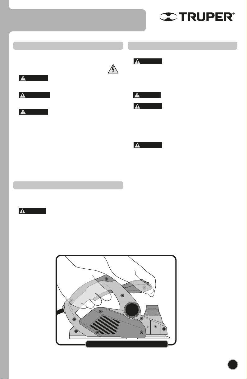
• Hold the tool firmly using both hands.
• Keep your hands away from the
rotating parts.
• Double check the blades are not
making contact with the work piece when turning ON the
machine.
• Before cutting, wait until the blades reach the maximum
speed.
• Work with the machine setting it at least 8” away from
your face and body.
• Never leave the tool running with no
supervision. Handle the tool only when you can control it
with both hands. Turn it OFF before leaving it aside.
• After long periods of functioning, the tool metallic parts
may be very hot.
While Operating the Tool
DANGER
DANGER
CAUTION
CAUTION
CAUTION
CAUTION
CAUTION
WARNING
Right Way to Operate the Planer
ENGLISH
Safety warnings for
electric planers
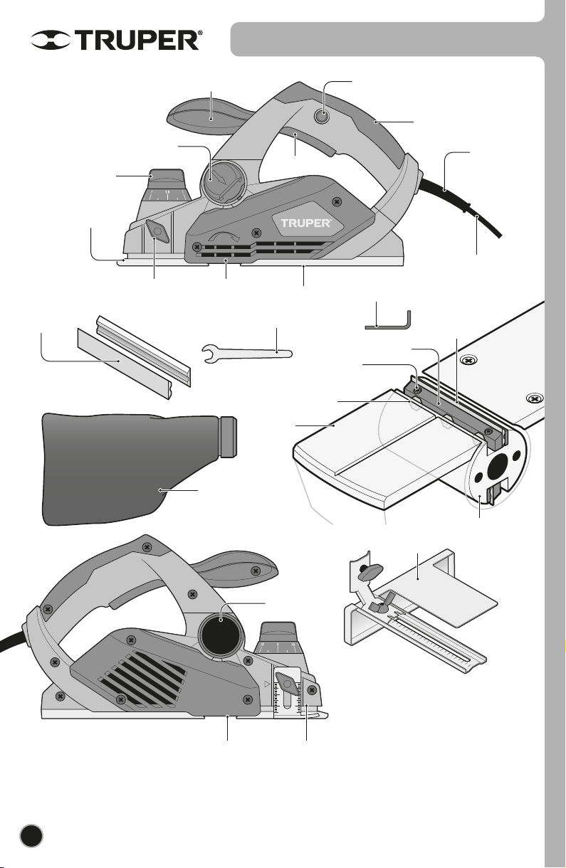
Parts
Cutting Depth
Adjusting Knob
Handle
Switch
Lock
Supporting
Block
Adjustable
Base
Dust
Collecting
Pouch
Blades
Adjusting
Screws
Fixed Base
Fixed
Base
Parallel Guide
Fastening Knob
Cutter
Head
Band Cover
0.31” Spanner
Cut-off
Guide
Cutter
Head Guard
Adjustable
Base
Auxiliar
Handle
Blocking
Lock
Blade
Blades
Parallel Guide
Switch
6
Power Cord
Protector
Power
Cord
Height
Control
Screws
0.09”
Hexagonal Wrench
ENGLISH
Shavings
Expelling
Duct
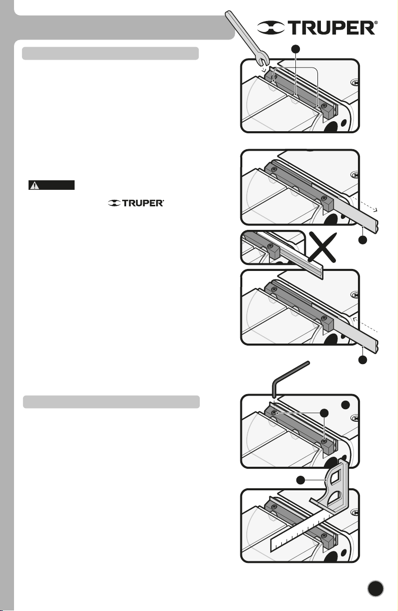
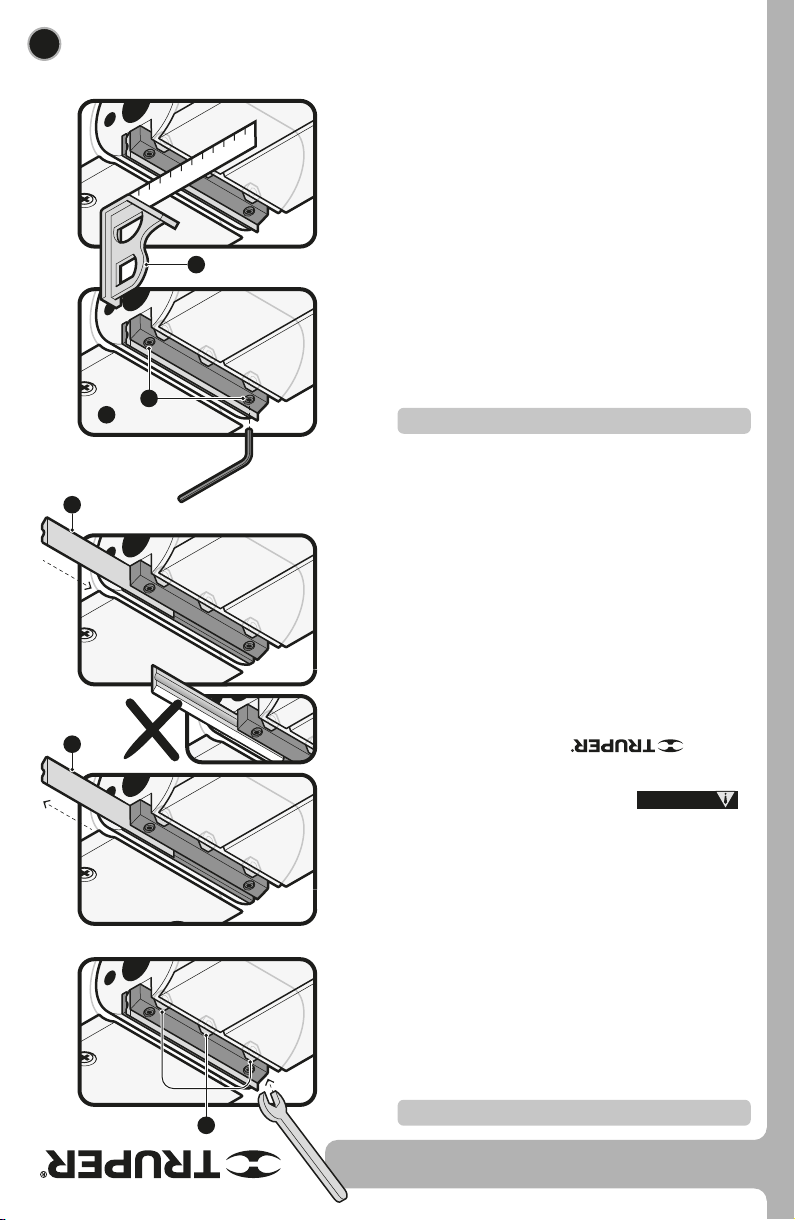
Blades Set Up
7
Assembly
ENGLISH
The blades must be adjusted so that the cutting edge is
level with the fixed base. (See "Blade leveling" below).
• To remove the worn blades, loosen the three adjusting
screws (A) with the included 8 mm wrench, turning them
counterclockwise.
• Slide the worn-out blade (B) through the cutting head
support block.
• With the worn blade out, now slide the new blade (C)
through the block and align the blades across the block.
• Tighten the three adjusting screws firmly. Remember that
a loose screw could be extremely dangerous. Check
regularly to see if they are tightened properly.
• Repeat the operation with the other blade.
Before installing the blades, turn off and
disconnect the tool, and clean any chips or foreign matter
from the cutting head. Use
replacement blades with the same dimensions and weight
or the cutting head will oscillate and vibrate causing poor
planning and perhaps machine breakdown.
• The blades are sharp on both sides. If one side becomes
dull or worn, turn it over to use the sharp side. When both
blades are worn, replace the blade. Do not attempt to
sharpen it.
If you are replacing the blades, replace both at the same
time, otherwise vibration may occur which shortens the
life of the blades and the tool.
Blades leveling
The blades must be adjusted to the height of the base (D),
If this is not the case, follow the instructions below:
• Slightly loosen the adjusting screws (A) with the 8 mm
wrench.
• Using the 2.5 mm hexagonal wrench provided, turn the
height control screws (E) clockwise to go up, and
counterclockwise to go down, as required by the planner.
• Level the height by resting a set square (F) on the fixed
base and the adjustable base (set to 0).
• Finally, tighten the adjusting screws with the 8 mm
wrench.
B
C
D
A
E
F
CAUTION
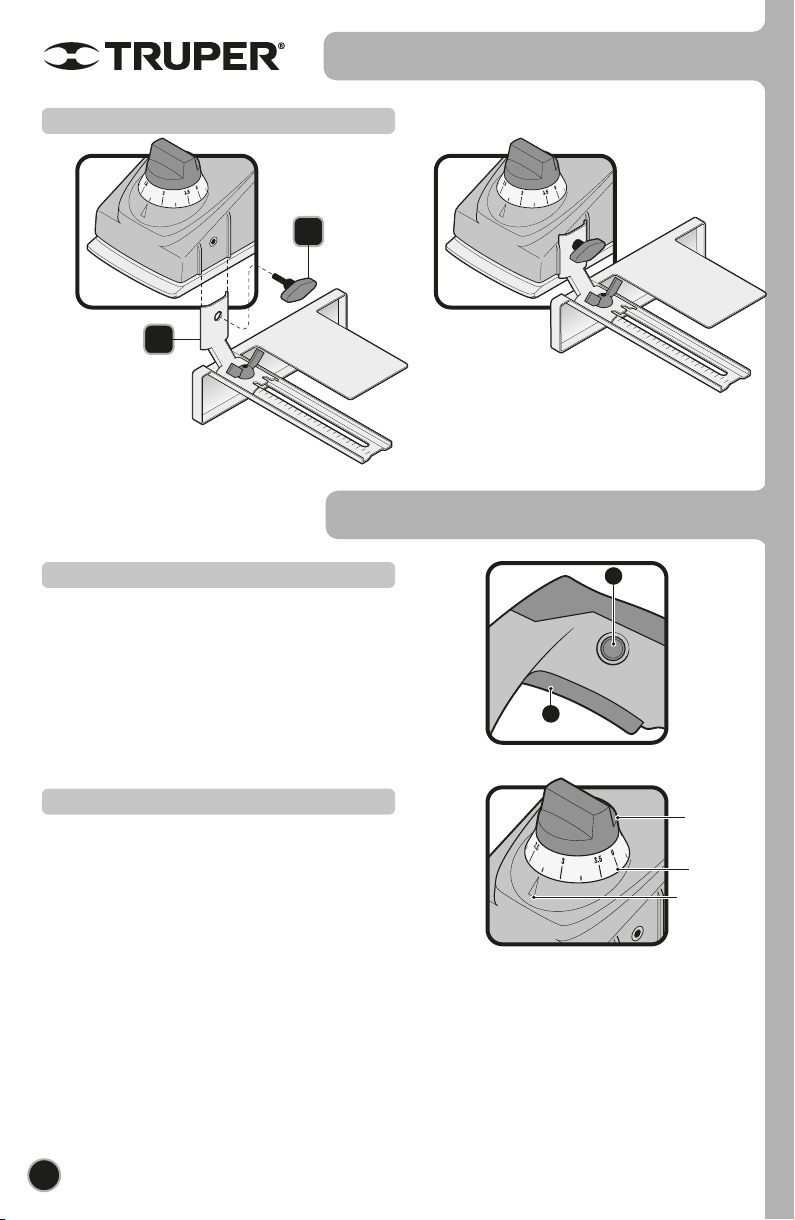
Triangular
Mark
Cutting
Depth
Adjusting
Knob
Graded
Ring
8
Start and Operation Control
• Connect the plug into the power outlet.
• Keep the switch lock (B) pressed to unblock the switch (A).
The switch lock prevents from accidentally starting up the tool.
• Press the switch (A) to start the cutter head in motion.
• To stop the cutter head, release the switch (A).
Cutting Depth Adjustment
• Turn the cutting depth adjusting knob and match the
measurement in millimeters indicated in the knob graded
ring with the triangular mark so that the adjustable base is
set in the desired height.
• To determine precise cutting depths, plan a piece of
scrap wood, measure the thickness difference and if
necessary, adjust to the needed value.
Assembly
Parallel Guide Set Up
1
2
Start Up
ENGLISH
A
B

• Set the adjustable base onto the work piece surface. The
blades should not make contact with the piece (figure 1).
• Start the tool and wait for the blades to reach the maximum
speed.
• Holding the tool with both hands, advance it gently by
applying pressure to the front of the auxiliary handle (2). Planing
will be easier if the workpiece is slightly inclined so that the
planing is downwards.
• Push the tool beyond the work piece but not leaning
downwards (3).
• The planing speed and cutting depth determine the finish
quality. To get a rough cut increase the cutting depth. To get a
fine finish diminish the cutting depth and push the tool slower.
An extremely fast pass of the tool may produce
bad quality cuts and will damage the blades or the motor. If the
movement is to slow, you may burn or damage the cut.
The right advancing speed will be dependent of the type of
material being cut and the planning depth. Before planning the
work piece, make some tests using a piece of scrap wood to
gauge the right speed and the dimensions of the cut.
Secure the work piece using clamps to prevent
accidents and defects in the cut.
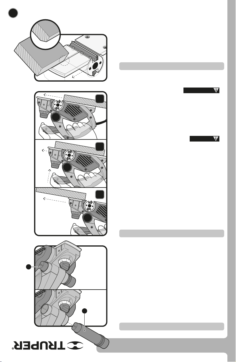
Planing
• For bevel cuts or chamfers, match the work piece edge with
one of the two notches in the adjustable base.
• Make passes with the planer aligning the notch on the corner
edge.
Bevel Cuts
• The brush has a shavings ejector duct that can be positioned to
eject from the right or left (A)
• The duct runs through the brush from side to side through the
ejector ducts, blocking one of the ducts and allowing shavings to
exit through the other. To release the duct, move the locking
latch (B) in the direction indicated by the arrow and push it out.
To place it, insert it from the right or left and push it until it is
locked by the lock.
• You can attach the dust collection bag to the open chip ejector
for easy disposal.
• You can connect a workshop dust extraction system or a
household vacuum cleaner to the chip ejector, making the
working environment safer and cleaner.
Shaving extraction
9
Start Up
1
2
3
CAUTION
WARNING
ENGLISH
A
B

• Keep the tool dust-free. Never use water or chemical
substances to clean the tool. Use only a clean and dry
cloth.
• Always keep the ventilation slots clean and free of
obstructions to guarantee the adequate cooling of the
motor.
• Inspect regularly all the mounting screws. Make sure that
are tightly fastened. If a screw is loose, tighten immediately.
• The armature and motor are the power tool’s heart. Use
extreme care not to affect the tool with oil or water.
• In a regular basis, double-check the power cable. Look
for any type of damage. If the cable is damaged take it to a
Authorized Service Center.
Disconnect the cable from the power outlet before carrying out any adjustment,
service or maintenance to the tool.
Servicing the tool shall only be carried out in a
Authorized Service Center.
Service and maintenance carried out by non-qualified
people may be dangerous and may cause personal
injuries. It also makes the Warranty void.
Cleaning and Care
Carbon Brush Replacement
Service
WARNING
10
Notas
• Carbon Brushes should be periodically checked and
when worn, replaced always in a
Authorized Service Center.
• After replacing the carbon brushes request to inspect if
the new carbon brushes can move freely in the carbon
housing. Also request to run the tool 5 minutes to make
even the contact with the carbon brushes and the
commuter.
• Use only original spare carbon
brushes specifically designed with the hardness and
resistance adequate for each type of motor. Carbons
that are out of specification could damage the motor.
• When replacing carbon brushes, always replace both.
ENGLISH
Maintenance

11
Authorized Service Centers
ENGLISH
In the event of any problem contacting a Authorized Service Center, please see our webpage
www.truper.com to get an updated list, or call our toll-free numbers 800 690-6990 or 800 0187-8737 to get
information about the nearest Service Center.
AGUASCALIENTES
BAJA
CALIFORNIA
BAJA
CALIFORNIA SUR
CAMPECHE
CHIAPAS
CHIHUAHUA
MEXICO CITY
COAHUILA
COLIMA
DURANGO
ESTADO DE
MÉXICO
GUANAJUATO
GUERRERO
HIDALGO
JALISCO
MICHOACÁN
MORELOS
NAYARIT
NUEVO LEÓN
OAXACA
PUEBLA
QUERÉTARO
QUINTANA ROO
SAN LUIS
POTOSÍ
SINALOA
SONORA
TABASCO
TAMAULIPAS
TLAXCALA
VERACRUZ
YUCATÁN
DE TODO PARA LA CONSTRUCCIÓN
GRAL. BARRAGÁN #1201, COL. GREMIAL, C.P. 20030,
AGUASCALIENTES, AGS. TEL.: 449 994 0537
SUCURSAL TIJUANA
AV. LA ENCANTADA, LOTE #5, PARQUE INDUSTRIAL EL
FLORIDO II, C.P 22244, TIJUANA, B.C.
TEL.: 664 969 5100
FIX FERRETERÍAS
FELIPE ÁNGELES ESQ. RUIZ CORTÍNEZ S/N, COL. PUEBLO
NUEVO, C.P. 23670, CD. CONSTITUCIÓN, B.C.S.
TEL.: 613 132 1115
TORNILLERÍA Y FERRETERÍA AAA
AV. ÁLVARO OBREGÓN #324, COL. ESPERANZA
C.P. 24080 CAMPECHE, CAMP. TEL.: 981 815 2808
FIX FERRETERÍAS
AV. CENTRAL SUR #27, COL. CENTRO, C.P. 30700,
TAPACHULA, CHIS. TEL.: 962 118 4083
SUCURSAL CHIHUAHUA
AV. SILVESTRE TERRAZAS #128-11, PARQUE INDUSTRIAL
BAFAR, CARRETERA MÉXICO CUAUHTÉMOC, C.P. 31415,
CHIHUAHUA, CHIH. TEL. 614 434 0052
FIX FERRETERÍAS
EL MONSTRUO DE CORREGIDORA, CORREGIDORA # 22,
COL. CENTRO, C.P. 06060, CUAUHTÉMOC, CDMX.
TEL: 55 5522 5031 / 5522 4861
SUCURSAL TORREÓN
CALLE METAL MECÁNICA #280, PARQUE INDUSTRIAL
ORIENTE, C.P. 27278, TORREÓN, COAH.
TEL.: 871 209 68 23
BOMBAS Y MOTORES BYMTESA DE MANZANILLO
BLVD. MIGUEL DE LA MADRID #190, COL. 16 DE
SEPTIEMBRE, C.P. 28239, MANZANILLO, COL.
TEL.: 314 332 1986 / 332 8013
TORNILLOS ÁGUILA, S.A. DE C.V.
MAZURIO #200, COL. LUIS ECHEVERRÍA, DURANGO,
DGO.TEL.: 618 817 1946 / 618 818 2844
SUCURSAL CENTRO JILOTEPEC
AV. PARQUE INDUSTRIAL #1-A, C.P. 54240, JILOTEPEC,
EDO. DE MÉX. TEL: 761 782 9101 EXT. 5728 Y 5102
CÍA. FERRETERA NUEVO MUNDO S.A. DE C.V.
AV. MÉXICO - JAPÓN #225, CD. INDUSTRIAL, C.P. 38010,
CELAYA, GTO. TEL.: 461 617 7578 / 79 / 80 / 88
CENTRO DE SERVICIO ECLIPSE
CALLE PRINCIPAL MZ.1 LT. 1, COL. SANTA FE, C.P. 39010,
CHILPANCINGO, GRO. TEL.: 747 478 5793
FERREPRECIOS S.A. DE C.V.
LIBERTAD ORIENTE #304 LOCAL 30, INTERIOR DE PASAJE
ROBLEDO, COL. CENTRO, C.P. 43600, TULANCINGO,
HGO. TEL.: 775 753 6615 / 775 753 6616
SUCURSAL GUADALAJARA
AV. ADOLFO B. HORN # 6800, COL: SANTA CRUZ DEL
VALLE, C.P.: 45655, TLAJOMULCO DE ZUÑIGA, JAL.
TEL.: 33 3606 5285 AL 90
FIX FERRETERÍAS
AV. PASEO DE LA REPÚBLICA #3140-A, COL.
EX-HACIENDA DE LA HUERTA, C.P. 58050, MORELIA,
MICH. TEL.: 443 334 6858
FIX FERRETERÍAS
CAPITÁN ANZURES #95, ESQ. JOSÉ PERDIZ, COL.
CENTRO, C.P. 62740, CUAUTLA, MOR.
TEL.: 735 352 8931
HERRAMIENTAS DE TEPIC
MAZATLAN #117, COL. CENTRO, C.P. 63000, TEPIC, NAY.
TEL.: 311 258 0540
SUCURSAL MONTERREY
CARRETERA LAREDO #300, 1B MONTERREY PARKS,
COLONIA PUERTA DE ANÁHUAC, C.P. 66052, ESCOBEDO,
NUEVO LEÓN, TEL.: 81 8352 8791 / 81 8352 8790
FIX FERRETERÍAS
AV. 20 DE NOVIEMBRE #910, COL. CENTRO, C.P. 68300,
TUXTEPEC, OAX. TEL.: 287 106 3092
SUCURSAL PUEBLA
AV PERIFÉRICO #2-A, SAN LORENZO ALMECATLA,
C.P. 72710, CUAUTLACINGO, PUE.
TEL.: 222 282 8282 / 84 / 85 / 86
ARU HERRAMIENTAS S.A DE C.V.
AV. PUERTO DE VERACRUZ #110, COL. RANCHO DE
ENMEDIO, C.P. 76842, SAN JUAN DEL RÍO, QRO.
TEL.: 427 268 4544
FIX FERRETERÍAS
CARRETERA FEDERAL MZ. 46 LT. 3 LOCAL 2, COL EJIDAL,
C.P. 77710 PLAYA DEL CARMEN, Q.R.
TEL.: 984 267 3140
FIX FERRETERÍAS
AV. UNIVERSIDAD #1850, COL. EL PASEO, C.P. 78320,
SAN LUIS POTOSÍ, S.L.P. TEL.: 444 822 4341
SUCURSAL CULIACÁN
AV. JESÚS KUMATE SUR #4301, COL. HACIENDA DE LA
MORA, C.P. 80143, CULIACÁN, SIN.
TEL.: 667 173 9139 / 173 8400
FIX FERRETERÍAS
CALLE 5 DE FEBRERO #517, SUR LT. 25 MZ. 10, COL.
CENTRO, C.P. 85000, CD. OBREGÓN, SON.
TEL.: 644 413 2392
SUCURSAL VILLAHERMOSA
CALLE HELIO LOTES 1, 2 Y 3 MZ. #1, COL. INDUSTRIAL,
2A ETAPA, C.P. 86010, VILLAHERMOSA, TAB.
TEL.: 993 353 7244
VM ORINGS Y REFACCIONES
CALLE ROSITA #527 ENTRE 20 DE NOVIEMBRE Y GRAL.
RODRÍGUEZ, FRACC. REYNOSA, C.P. 88780, REYNOSA,
TAMS. TEL.: 899 926 7552
SERVICIOS Y HERRAMIENTAS INDUSTRIALES
PABLO SIDAR #132, COL . BARRIO DE SAN BARTOLOMÉ,
C.P. 90970, SAN PABLO DEL MONTE, TLAX.
TEL.: 222 271 7502
LA CASA DISTRIBUIDORA TRUPER
BLVD. PRIMAVERA. ESQ. HORTENSIA S/N, COL.
PRIMAVERA C.P. 93308, POZA RICA, VER.
TEL.: 782 823 8100 / 826 8484
SUCURSAL MÉRIDA
CALLE 33 #600 Y 602, LOCALIDAD ITZINCAB Y MULSAY,
MPIO. UMÁN, C.P. 97390, MÉRIDA, YUC.
TEL.: 999 912 2451

12 ENGLISH
2
YEARS
www.truper.com
10-2020
CEPEL-3-1/4A4
Warranty
policy
Stamp of the business. Delivery date:
Model
100502
Code Brand
This product is guaranteed for 2 years. To make the warranty valid or purchase parts and components you
must present the product in Corregidora 22, Col. Centro, Alc. Cuauhtémoc, CDMX C.P. 06060 or at the
establishment where you purchased it, or at any Truper®Service Center listed in the annex to the warranty
policy and/or in www.truper.com . Transportation costs resulting from compliance of this warranty will be
covered by
For questions or comments, call 800-690-6990. Made in China. Imported by Truper S.A. de C.V. Parque
Industrial 1, Jilotepec, Edo. de Méx. C.P. 54240

12 ESPAÑOL
2
AÑOS
CEPEL-3-1/4A4
Póliza de
Garantía
www.truper.com
10-2020
Sello del establecimiento comercial. Fecha de entrega:
Modelo
100502
Código Marca
Este producto está garantizado por 2 años. Para hacer válida la garantía o adquirir piezas y componentes deberá
presentar el producto en Corregidora 22, Col. Centro, Alc. Cuauhtémoc, CDMX C.P. 06060 o en el
establecimiento donde lo compró, o en algún Centro de Servicio Truper®de los enlistados en el anexo de la
póliza de garantía y/o en www.truper.com . Los gastos de transportación que resulten para su cumplimiento
serán cubiertos por
Para dudas o comentarios, llame al 800-690-6990. Hecho en China. Importado por Truper S.A. de C.V. Parque
Industrial 1, Jilotepec, Edo. de Méx. C.P. 54240

11
Centros de Servicio Autorizados
ESPAÑOL
En caso de tener algún problema para contactar un Centro de Servicio Autorizado
consulte nuestra página www.truper.com donde obtendrá un listado actualizado, o llame al:
800 690-6990 ó800 0187-8737 donde le informarán cuál es el Centro de Servicio más cercano.
AGUASCALIENTES
BAJA
CALIFORNIA
BAJA
CALIFORNIA SUR
CAMPECHE
CHIAPAS
CHIHUAHUA
CIUDAD DE
MÉXICO
COAHUILA
COLIMA
DURANGO
ESTADO DE
MÉXICO
GUANAJUATO
GUERRERO
HIDALGO
JALISCO
MICHOACÁN
MORELOS
NAYARIT
NUEVO LEÓN
OAXACA
PUEBLA
QUERÉTARO
QUINTANA ROO
SAN LUIS
POTOSÍ
SINALOA
SONORA
TABASCO
TAMAULIPAS
TLAXCALA
VERACRUZ
YUCATÁN
DE TODO PARA LA CONSTRUCCIÓN
GRAL. BARRAGÁN #1201, COL. GREMIAL, C.P. 20030,
AGUASCALIENTES, AGS. TEL.: 449 994 0537
SUCURSAL TIJUANA
AV. LA ENCANTADA, LOTE #5, PARQUE INDUSTRIAL EL
FLORIDO II, C.P 22244, TIJUANA, B.C.
TEL.: 664 969 5100
FIX FERRETERÍAS
FELIPE ÁNGELES ESQ. RUIZ CORTÍNEZ S/N, COL. PUEBLO
NUEVO, C.P. 23670, CD. CONSTITUCIÓN, B.C.S.
TEL.: 613 132 1115
TORNILLERÍA Y FERRETERÍA AAA
AV. ÁLVARO OBREGÓN #324, COL. ESPERANZA
C.P. 24080 CAMPECHE, CAMP. TEL.: 981 815 2808
FIX FERRETERÍAS
AV. CENTRAL SUR #27, COL. CENTRO, C.P. 30700,
TAPACHULA, CHIS. TEL.: 962 118 4083
SUCURSAL CHIHUAHUA
AV. SILVESTRE TERRAZAS #128-11, PARQUE INDUSTRIAL
BAFAR, CARRETERA MÉXICO CUAUHTÉMOC, C.P. 31415,
CHIHUAHUA, CHIH. TEL. 614 434 0052
FIX FERRETERÍAS
EL MONSTRUO DE CORREGIDORA, CORREGIDORA # 22,
COL. CENTRO, C.P. 06060, CUAUHTÉMOC, CDMX.
TEL: 55 5522 5031 / 5522 4861
SUCURSAL TORREÓN
CALLE METAL MECÁNICA #280, PARQUE INDUSTRIAL
ORIENTE, C.P. 27278, TORREÓN, COAH.
TEL.: 871 209 68 23
BOMBAS Y MOTORES BYMTESA DE MANZANILLO
BLVD. MIGUEL DE LA MADRID #190, COL. 16 DE
SEPTIEMBRE, C.P. 28239, MANZANILLO, COL.
TEL.: 314 332 1986 / 332 8013
TORNILLOS ÁGUILA, S.A. DE C.V.
MAZURIO #200, COL. LUIS ECHEVERRÍA, DURANGO,
DGO.TEL.: 618 817 1946 / 618 818 2844
SUCURSAL CENTRO JILOTEPEC
AV. PARQUE INDUSTRIAL #1-A, C.P. 54240, JILOTEPEC,
EDO. DE MÉX. TEL: 761 782 9101 EXT. 5728 Y 5102
CÍA. FERRETERA NUEVO MUNDO S.A. DE C.V.
AV. MÉXICO - JAPÓN #225, CD. INDUSTRIAL, C.P. 38010,
CELAYA, GTO. TEL.: 461 617 7578 / 79 / 80 / 88
CENTRO DE SERVICIO ECLIPSE
CALLE PRINCIPAL MZ.1 LT. 1, COL. SANTA FE, C.P. 39010,
CHILPANCINGO, GRO. TEL.: 747 478 5793
FERREPRECIOS S.A. DE C.V.
LIBERTAD ORIENTE #304 LOCAL 30, INTERIOR DE PASAJE
ROBLEDO, COL. CENTRO, C.P. 43600, TULANCINGO,
HGO. TEL.: 775 753 6615 / 775 753 6616
SUCURSAL GUADALAJARA
AV. ADOLFO B. HORN # 6800, COL: SANTA CRUZ DEL
VALLE, C.P.: 45655, TLAJOMULCO DE ZUÑIGA, JAL.
TEL.: 33 3606 5285 AL 90
FIX FERRETERÍAS
AV. PASEO DE LA REPÚBLICA #3140-A, COL.
EX-HACIENDA DE LA HUERTA, C.P. 58050, MORELIA,
MICH. TEL.: 443 334 6858
FIX FERRETERÍAS
CAPITÁN ANZURES #95, ESQ. JOSÉ PERDIZ, COL.
CENTRO, C.P. 62740, CUAUTLA, MOR.
TEL.: 735 352 8931
HERRAMIENTAS DE TEPIC
MAZATLAN #117, COL. CENTRO, C.P. 63000, TEPIC, NAY.
TEL.: 311 258 0540
SUCURSAL MONTERREY
CARRETERA LAREDO #300, 1B MONTERREY PARKS,
COLONIA PUERTA DE ANÁHUAC, C.P. 66052, ESCOBEDO,
NUEVO LEÓN, TEL.: 81 8352 8791 / 81 8352 8790
FIX FERRETERÍAS
AV. 20 DE NOVIEMBRE #910, COL. CENTRO, C.P. 68300,
TUXTEPEC, OAX. TEL.: 287 106 3092
SUCURSAL PUEBLA
AV PERIFÉRICO #2-A, SAN LORENZO ALMECATLA,
C.P. 72710, CUAUTLACINGO, PUE.
TEL.: 222 282 8282 / 84 / 85 / 86
ARU HERRAMIENTAS S.A DE C.V.
AV. PUERTO DE VERACRUZ #110, COL. RANCHO DE
ENMEDIO, C.P. 76842, SAN JUAN DEL RÍO, QRO.
TEL.: 427 268 4544
FIX FERRETERÍAS
CARRETERA FEDERAL MZ. 46 LT. 3 LOCAL 2, COL EJIDAL,
C.P. 77710 PLAYA DEL CARMEN, Q.R.
TEL.: 984 267 3140
FIX FERRETERÍAS
AV. UNIVERSIDAD #1850, COL. EL PASEO, C.P. 78320,
SAN LUIS POTOSÍ, S.L.P. TEL.: 444 822 4341
SUCURSAL CULIACÁN
AV. JESÚS KUMATE SUR #4301, COL. HACIENDA DE LA
MORA, C.P. 80143, CULIACÁN, SIN.
TEL.: 667 173 9139 / 173 8400
FIX FERRETERÍAS
CALLE 5 DE FEBRERO #517, SUR LT. 25 MZ. 10, COL.
CENTRO, C.P. 85000, CD. OBREGÓN, SON.
TEL.: 644 413 2392
SUCURSAL VILLAHERMOSA
CALLE HELIO LOTES 1, 2 Y 3 MZ. #1, COL. INDUSTRIAL,
2A ETAPA, C.P. 86010, VILLAHERMOSA, TAB.
TEL.: 993 353 7244
VM ORINGS Y REFACCIONES
CALLE ROSITA #527 ENTRE 20 DE NOVIEMBRE Y GRAL.
RODRÍGUEZ, FRACC. REYNOSA, C.P. 88780, REYNOSA,
TAMS. TEL.: 899 926 7552
SERVICIOS Y HERRAMIENTAS INDUSTRIALES
PABLO SIDAR #132, COL . BARRIO DE SAN BARTOLOMÉ,
C.P. 90970, SAN PABLO DEL MONTE, TLAX.
TEL.: 222 271 7502
LA CASA DISTRIBUIDORA TRUPER
BLVD. PRIMAVERA. ESQ. HORTENSIA S/N, COL.
PRIMAVERA C.P. 93308, POZA RICA, VER.
TEL.: 782 823 8100 / 826 8484
SUCURSAL MÉRIDA
CALLE 33 #600 Y 602, LOCALIDAD ITZINCAB Y MULSAY,
MPIO. UMÁN, C.P. 97390, MÉRIDA, YUC.
TEL.: 999 912 2451

10
Mantenimiento
Notas
• Mantenga la herramienta libre de polvo. Nunca utilice
agua o limpiadores químicos para limpiar la herramienta.
Limpie solamente con un trapo limpio y seco.
• Siempre mantenga las ventilas limpias y libres de
obstrucciones para garantizar un enfriamiento adecuado
del motor.
• Inspeccione regularmente todos los tornillos de montaje
y asegúrese de que estén apretados correctamente. En
caso de que alguno de los tornillos esté suelto, apriételo
inmediatamente.
• La armadura y el motor son el corazón de la herramienta
eléctrica. Tenga mucho cuidado de que no se vean
afectados por aceite o agua.
• Revise periódicamente el cable de alimentación para
detectar cualquier tipo de daño. En caso de estar dañados,
haga cambiar el cable en un Centro de Servicio Autorizado
.
Desconecte el cable de alimentación del tomacorriente antes de hacer cualquier ajuste, servicio o
mantenimiento a la herramienta.
• El servicio de las herramientas debe ser realizado
únicamente en un Centro de Servicio Autorizado
. El servicio y mantenimiento
realizado por personas no calificadas puede resultar
peligroso y llegar a ocasionar daños personales además
de invalidar la garantía del producto.
Limpieza y cuidados Cambio de carbones
Servicio
ADVERTENCIA
• Los carbones deben revisarse periódicamente y ser
reemplazados siempre por un Centro de Servicio
Autorizado cuando se hayan
desgastado. Después de que hayan sido reemplazados,
pida que se inspeccione si los nuevos carbones pueden
moverse libremente en el porta-carbón y solicite que
enciendan la herramienta y la mantengan encendida
durante 5 minutos para emparejar el contacto de los
carbones y el conmutador.
• Sólo se deben de usar carbones de repuesto
originales, diseñados específica-
mente con la dureza y la resistencia eléctrica adecuada
para cada tipo de motor. Los carbones fuera de
especificaciones pueden dañar el motor.
• Cuando se haga el cambio de carbones siempre
deben cambiarse los dos carbones.
ESPAÑOL
• Apoye la base ajustable sobre la superficie de la pieza de
trabajo sin que las cuchillas hagan contacto con ella (1).
• Encienda la herramienta y espere a que las cuchillas alcancen
su máxima velocidad.
• Sosteniendo la herramienta con ambas manos hágala avanzar
con suavidad, aplicando presión al frente sobre el mango
auxiliar (2). El cepillado será más sencillo si la pieza de trabajo
se encuentra ligeramente inclinada, de modo que el cepillado
sea cuesta abajo.
• Empuje la herramienta más allá del borde de la pieza de
trabajo sin inclinarla hacia abajo (3).
• La velocidad de cepillado y la profundidad de corte
determinan la calidad del acabado. Para un corte áspero,
aumente la profundidad de corte; para un acabado fino
disminuya la profundidad de corte y haga avanzar la
herramienta más despacio.
Un avance demasiado rápido de la
herramienta puede producir cortes de mala calidad y daños a
las cuchillas o el motor. Si el desplazamiento es demasiado lento
se podrá quemar o estropear el corte.
La velocidad correcta de avance dependerá del tipo de material
que se esté cortando y la profundidad de cepillado. Haga
pruebas en un trozo de material de desecho para calibrar la
velocidad correcta de avance y las dimensiones de corte antes
de cepillar la pieza de trabajo.
Asegure la pieza de trabajo con
abrazaderas para evitar accidentes y defectos en el corte.
Cepillado
• Para hacer un corte en biselado, haga coincidir la esquina de la
pieza de trabajo con la ranura en V para biselado de la base
ajustable.
• Pase el cepillo alineando la ranura por el borde de esquina.
Cortes en biselado
• El cepillo tiene un ducto expulsor de virutas que puede
colocarse para expulsar por derecha o izquierda (A).
• El ducto atraviesa de lado a lado al cepillo a través de los
conductos expulsores, bloqueando uno de los conductos y
permitiendo la salida de virutas por el otro. Para liberar el ducto
mueva el seguro de bloqueo (B) en la dirección indicada por la
flecha y empújelo hacia afuera. Para colocarlo introdúzcalo por
la derecha o izquierda y empújelo hasta que sea bloqueado por
el seguro.
• Puede acoplar la bolsa recolectora de polvo al expulsor de
virutas abierto para facilitar su desecho.
• Puede conectar al expulsor de virutas un sistema de extracción
de polvo de taller o una aspiradora doméstica, lo que permitirá
que el ambiente de trabajo sea más seguro y esté más limpio.
Extracción de virutas
ATENCIÓN
ADVERTENCIA
9
Puesta en marcha
ESPAÑOL
A
B
1
2
3

Marca
triangular
Perilla de
ajuste de
profundidad
Anillo
graduado
Encendido y control de operación
Instalación de la guía paralela
• Conecte la clavija al tomacorriente.
• Mantenga presionado el seguro del interruptor (B) para
desbloquear el interruptor (A). El seguro del interruptor
evita encendidos accidentales.
• Presione el interruptor (A) para que la cabeza de corte
comience a girar.
• Para detener la cabeza de corte suelte el interruptor (A).
Ajuste de profundidad de corte
• Gire la perilla de ajuste de profundidad de corte y haga
coincidir la medida en milímetros indicada en el anillo
graduado de la perilla con la marca triangular para que la
base ajustable quede a la altura deseada.
• Si es necesario determinar con exactitud la profundidad
de corte, cepille un trozo de madera de desecho, mida la
diferencia del espesor y ajuste el valor en caso necesario.
1
2
8
Ensamble
Puesta en marcha
ESPAÑOL
A
B
Instalación de las cuchillas
Las cuchillas se deberán ajustar de tal forma que el filo de
corte quede nivelado a la altura de la base fija (Ver
“Nivelación de cuchillas” más abajo).
• Para retirar las cuchillas desgastadas, afloje los tres
tornillos de ajuste (A) con la llave de 8 mm incluida,
girándolos en contra de las manecillas del reloj.
• Deslice la cuchilla desgastada (B) a través del bloque de
soporte de la cabeza de corte.
• Con la cuchilla desgastada fuera, ahora deslice la cuchilla
nueva (C) a través del bloque y alinee las cuchillas a lo
ancho del bloque.
• Apriete uniformemente los tres tornillos de ajuste.
Recuerde que un tornillo flojo podría ser extremadamente
peligroso, verifique regularmente para ver si están
apretados correctamente.
• Repita la operación con la otra cuchilla.
Antes de instalar las cuchillas apague y
desconecte la herramienta, limpie las virutas o cualquier
materia extraña de la cabeza de corte. Utilice cuchillas de
repuesto con las mismas
dimensiones y el mismo peso o la cabeza de corte oscilará
y vibrará, causando un cepillado deficiente y quizá una
rotura de la máquina.
• La cuchillas tienen filo por ambos lados, si pierde filo o
se desgasta uno de los lados gírela para utilizar el lado
afilado. Cuando ambos lados estén desgastados
reemplace la cuchilla, no intente afilarlas.
Si va a reemplazar las cuchillas, reemplace las dos al
mismo tiempo; de lo contrario se pueden producir
vibraciones que acorten la vida útil de las cuchillas y la
herramienta.
Nivelación de cuchillas
Las cuchillas deben estar ajustadas a la altura de la base (D),
de no ser así siga las siguientes instrucciones:
• Afloje ligeramente los tornillos de ajuste (A) con la llave
de 8 mm.
• Con ayuda de la llave hexagonal de 2.5 mm incluida,
gire los tornillos para control de altura (E) en el sentido
de las manecillas de reloj para subir y en el sentido
opuesto a las manecillas de reloj para bajar, según lo
requiera su cepillo.
• Nivele la altura apoyando una escuadra (F) sobre la
base fija y la base ajustable (colocada en 0).
• Por ultimo apriete los tornillos de ajuste con la llave de
8 mm.
7
Ensamble
ATENCIÓN
ESPAÑOL
B
C
D
A
E
F

Partes
Perilla de ajuste
de profundidad
de corte
Mango
Mango
auxiliar Seguro del
interruptor
Ducto
expulsor
de virutas
Bloque de
soporte
Tornillos para
control de
altura
Base
ajustable
Bolsa
recolectora
de polvo
Tornillos de
ajuste de las
cuchillas
Base fija
Base
fija
Perilla de
sujeción de la
guía paralela
Cabezal
de corte
Cubierta
de la banda
Llave de 8 mm
Guía de
rebajado
Guarda de la
cabeza de corte
Base
ajustable
Seguro de
bloqueo
Cuchilla
Cuchillas
Guía paralela
Interruptor
6
Llave hexagonal
de 2.5 mm
Protector
del cable
Cable de
alimentación
ESPAÑOL

• Desenrolle por completo el cable de extensión para
evitar un sobrecalentamiento potencial.
• Asegúrese de que la tensión de la toma de corriente sea
igual a la tensión nominal descrita en la placa de su
herramienta.
• Retire del lugar de trabajo trapos,
ropa, cables, cuerdas, o cualquier cosa que pueda ser
atrapada por las cuchillas de la herramienta.
• Retire clavos, tornillos o cualquier
objeto de la pieza de trabajo. Estos dañarían las cuchillas y
la herramienta. Además, podrían representar un peligro
para su seguridad.
• Antes de iniciar cualquier trabajo,
asegúrese de que los tornillos de instalación de las
cuchillas estén bien apretados.
• Antes de operar la herramienta enciéndala y deje que
funcione unos momentos. Vea si hay vibraciones que
indiquen una mala instalación o una cuchilla mal
balanceada.
5
Antes de operar la herramienta
• Cuando termine de operar la herramienta, apáguela y accione el soporte de descanso girándolo hacia abajo para que las
cuchillas no entren en contacto con nada y colóquela sobre un bloque de madera.
• Antes de intentar cualquier ajuste, apague la herramienta y espere a que las cuchillas se detengan por completo.
• Nunca meta el dedo en el orificio de descarga de virutas. Para quitar el exceso apague y desconecte la
herramienta, utilice un palo para quitar las virutas.
• Cuando sea necesario cambie las dos cuchillas al mismo tiempo. De lo contrario, el desequilibrio resultante causará
vibraciones y acortaría la vida útil de las cuchillas y de la herramienta. Maneje las cuchillas con mucho cuidado.
Después de operar la herramienta
• Siempre que sea posible, use un sistema de extractor de
polvo.
• Al operar la herramienta sosténgala
solamente por el mango y sus partes aisladas. En caso de
hacer contacto con un cable oculto las partes metálicas
expuestas de la herramienta podrían dar una descarga al
operador.
• Sujete la herramienta firmemente, con las dos manos.
• Mantenga las manos lejos de las piezas
giratorias.
• Asegúrese de que las cuchillas no
estén en contacto con la pieza de trabajo al encender la
máquina.
• Antes de cortar, espere a que las cuchillas alcancen su
máxima velocidad.
• Maneje la herramienta por lo menos a 20 cm (8
pulgadas) de distancia de su rostro y cuerpo.
• Nunca deje la herramienta encendida
sin supervisión. Manéjela sólo cuando la controle con
ambas manos y apáguela antes de soltarla.
• Después de periodos prolongados de funcionamiento,
las partes metálicas pueden estar muy calientes.
Mientras opera la herramienta
PELIGRO
PELIGRO
ATENCIÓN
ATENCIÓN
ATENCIÓN
ATENCIÓN
ATENCIÓN
ADVERTENCIA
Advertencias de Seguridad
para uso de cepillos eléctricos
forma adecuada de operar el cepillo
ESPAÑOL
This manual suits for next models
1
Table of contents
Other Truper Planer manuals


