TruSteel DR-10 User manual

DR-10 CUTSHEET
AND OPERATING
MANUAL
1 — ast update: 2019/09/24
TruSteel
Copyright © 2019 TruSteel

Table of Contents
1. DR-10 OVERVIEW .............................................................................................................................. 1
2. IMPORTANT: READ THIS BEFORE PROCEEDING........................................................................... 2
3. PRE-INSTALLATION OVERVIEW ...................................................................................................... 3
4. DR-10 SETUP ILLUSTRATION........................................................................................................... 4
4.1. 1. DR-10 Vessel ......................................................................................................................... 5
4.2. 2. Mixer...................................................................................................................................... 6
4.3. 3. VFD (Variable Frequency Drive)............................................................................................. 7
4.4. 4. Chiller .................................................................................................................................... 8
4.5. 5. Vacuum Pump...................................................................................................................... 11
4.6. 6. Heater .................................................................................................................................. 13
5. ANCILLARY EQUIPMENT SPECIFICATION SHEET ........................................................................ 16
6. OPERATION & MAINTENANCE ....................................................................................................... 19
6.1. OPERATING PROCEDURE ..................................................................................................... 20

1. DR-10 OVERVIEW
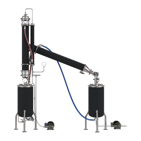
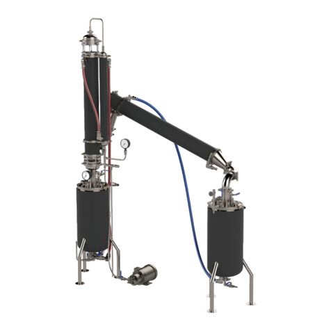
The DR-10 Decarboxylation Reactor is capable of devolatizing
and decarbing up to 10 gallons of material per run.
Material is heated and mixed while under a low vacuum. Non-desirables
will evaporate and exit from the exchanger “arm”.
The jacketed vessel is heated with an oil heater which pumps hot
transfer oil through the vessel jacket. The crude material is mixed by the
motor/shaft/prop set on top of the vessel.
The condenser arm is cooled by a chiller unit. The system is under
vacuum.
Parts of the DR-10
1. Vessel w/ condenser arm
2. Mixer; controlled by a Variable Drive w/remote
3. Hot Oil Heater
Stainless steel braided hoses included with fittings; (1) 48” hose, (1) 72” hose
4. Chiller Unit (hoses included)
5. Vaccum Pump (hose included)
6. Kevlar heat protection jacket and a protective Kevlar glove
TruSteel DR-10 CUTSHEET AND OPERATING MANUA - 1
Page 1 of 21

2. IMPORTANT: READ THIS BEFORE
PROCEEDING
TruSteel maintains this packet to provide general guidance to our customers. The recommendations
expressed herein represent the views only of our professional staff. They have not been reviewed or
approved by any organization that developed the local electrical, fire, and plumbing codes or standards.
These recommendations are based upon the best available information at the time they were written and
are not intended to and do not constitute professional electrician or plumbing advice or official
interpretations of any code or code provision.
ocal building, fire, and energy codes govern legal requirements at the state, county, and municipal
levels. They vary widely from jurisdiction to jurisdiction and can change frequently. Those local codes
take precedence over TruSteel floor plans. Please consult the applicable edition of your local codes.
TruSteel expressly disclaims any liability resulting from reliance upon the recommendations or opinions
expressed in this packet and makes no representations, warranties, or claims of any kind concerning the
accuracy or completeness of the information presented in this packet.
TruSteel DR-10 CUTSHEET AND OPERATING MANUA - 1
Page 2 of 21

3. PRE-INSTALLATION OVERVIEW
This Pre-Installation Guide describes the requirements for preparing for your TruSteel DR-10 installation.
This information in this manual serves as a recommended guide to help you and your contractors
successfully install all required electrical and plumbing for the ancillary equipment.
This guide covers all electrical and plumbing specifications for the chiller, heater, drive panel, and
vacuum pump. This guide does not describe the installation of the DR-10 itself as it is highly
recommended you hire a TruSteel certified installation contractor.
The following portion describes the steps to completing your pre-installation and setting up your DR-10
installation date:
1. Full Payment Recieved
2. DR-10 Shipped (includes all equipment) Note: there may be a case where some parts must be
shipped separate.
3. TruSteel requires the client to properly install (electric) all equipment according to code.
Note: For C1D2 compliancy, all ancillary equipment shall be placed outside the room that the
DR-10 will be run.
The DR-10 vessel and the Mixer Motor are C1D2 compliant.
The hot oil heater and the mixer require 3-phase electrical hookups. The chiller and vacuum pump
require 115V switches.
4. An installation date is determined.
A TruSteel Certied installation technician will contact you to oversee the pre-installation
requirements. A target date can be set for the install. As long as all requirements are met, the
install date will be confirmed.
5. The DR-10 will be installed with training.
The DR-10 installation will be signed off by the client with 100% satisfaction and a 1 year
warranty.
TruSteel DR-10 CUTSHEET AND OPERATING MANUA - 1
Page 3 of 21

4.1. 1. DR-10 Vessel
This is the DR-10 vessel with the condenser “arm”. All parts of this vessel are supplied by TruSteel.
Parts List
1. 13-gallon vessel with legs
2. Condenser arm with all clamps and valves (vacuum valve, discharge valve)
3. Feed hose (60“ long 1/2” diameter stainless steel braided hose with 1/2” Swagelok tube adaptor/stub)
– Customer is responsible to adpat this hose to their feed vessel
4. Discharge – the discharge can be adapted two different ways. The standard setup is a 1/2” tube
“spiket” that can be discharged into a bucket or jar. The second option is to use the 48” long 1/2”
diameter stainless steel braided hose with a 1/2” Swagelok tube adaptor/stub that the customer can use
with a collection vessel.
5. Compression adapator – used to apply pressure to discharge material from system. Air/N2
compressor NOT supplied by TruSteel.
6. Pressure/Vacuum Gauge
7. Kevlar jacket for vessel
8. Cover for condenser arm
Setup Required by Customer
There is essentially no setup required. You should have a dedicated space for the DR-10 that is next to
the wall separating your C1D2 Room and your Non-C1D2 Utility Room.
TruSteel DR-10 CUTSHEET AND OPERATING MANUA - 1
Page 5 of 21

4.2. 2. Mixer
This is the C1D2/C1D1 Compliant Mixer that sits on top of the DR-10 vessel.
Parts List
1. Mixer Motor
2. Shaft
3. (2) Props
Setup Required by Customer
You do not need to place the mixer at this point. You will need an electrician available at the installation
to tie in the electrical wires (conduit). The conduit can be setup without being landed, before the install
date.
TruSteel DR-10 CUTSHEET AND OPERATING MANUA - 1
Page 6 of 21

4.3. 3. VFD (Variable Frequency Drive)
The VFD (Variable Frequency Drive) supplies power to, and controls, the mixer motor.
The VFD requires single phase wiring from your electrical panel to the VFD, then 3 phase wiring from the
VFD to the mixer motor. TruSteel suggests placing a J-Box when contining the 3 phase wiring conduit
through the wall.
Parts List
1. enze VFD
2. Remote Control (includes 8 feet of CAT5)
Setup Required by Customer
1. Mount VFD to wall inside NON-C1D2 room
2. Run single phase electric into the VFD.
3. Run 3 phase electric to a j-box on the wall
4. Continue 3 phase electric from j-box to where mixer will “live”
5. On day of install, electrician will be required to land wires to mixer motor
TruSteel DR-10 CUTSHEET AND OPERATING MANUA - 1
Page 7 of 21

4.4. 4. Chiller
The chiller unit is used to cool the condenser “arm”.
Parts List
1. Chiller Unit
2. Connection tubing included (1/2” silicone)
Not Included:
1 gallon of glycol
10 feet of 1/2” silicone tubing (for plumbing inside room)
Insulation for silicone tubing
All copper plumbing and 1/2” hose barbs
Setup Required by Customer
1. Have either a plug, or a 110V wall switch (recommended)
to power the chiller
2. Run copper plumbing to the 1/2” hose barbs
3. Make sure you have enough silicone hose inside the
room to reach your DR-10 unit
Note: The chiller run inside the room should not be more than 5 feet.
TruSteel DR-10 CUTSHEET AND OPERATING MANUA - 1
Page 8 of 21

Helpful Images
Plumbing from chiller to the wall. 1/2” silicone tubing to copper plumbing securely mounted to wall.
TruSteel DR-10 CUTSHEET AND OPERATING MANUA - 1
Page 9 of 21

Plumbing inside wall of DR-10 room. Copper plumbing to 1/2” hose barb. Each run has about 5 feet of
insulated silicon tubing.
TruSteel DR-10 CUTSHEET AND OPERATING MANUA - 1
Page 10 of 21

4.5. 5. Vacuum Pump
The Vacuum pump should be placed OUTSIDE your C1D2 room, along with your other ancillary
equipment.
Parts List
1. Vacuum Pump
2. Vacuum Pump Oil (in vacuum pump box)
3. 10 feet of 1/2” braided silicone hose
Not Included:
Copper plumbing and hose barbs to go through the wall.
Setup Required by Customer
1. Have either a plug, or a 110V wall switch (recommended)
to power the vacuum pump
2. Run copper plumbing to the 1/2” hose barbs
Helpful Images
TruSteel DR-10 CUTSHEET AND OPERATING MANUA - 1
Page 11 of 21

A top view of the vacuum pump with braided silicone hose going to a hose barb on the wall.
Vacuum pump hose( 1/2” braided silicone hose) coming into DR-10 room
TruSteel DR-10 CUTSHEET AND OPERATING MANUA - 1
Page 12 of 21

4.6. 6. Heater
The heater is a hot mineral oil heater.
Parts List
1. Oil Heater
2. 10 gallons of Mineral Oil
3. 3/4” inline Check Valve
4. (1) 72” long 3/4” diameter braided stainless steel hose with fittings and valves
5. (1) 48” long 3/4” diameter braided stainless steel hose with fittings and valves
Setup Required by Customer
1. Determine the placement of the heater unit. Note: With the check valve used in the outlet line, the unit
can sit on the floor. Without the check valve, the unit will need to sit on a table about 3-4 feet high.
2. Plumbing setup from heater to the wall. Use 3/4” copper with NO F UX and NO PIPE DOPE. Place
the Check Valve supplied on the outlet run of the copper plumbing. See images below for a better view
of the plumbing.
3. Run the 3 phase electric required to the heater.
NOTE: The DR-10 unit should close enough to the wall so that the supplied braided stainless hoses
reach the unit from the wall. Please do not try to extend these hoses.
TruSteel DR-10 CUTSHEET AND OPERATING MANUA - 1
Page 13 of 21

Helpful Images
This is a front view look at the hot mineral oil heater. Note that it is placed very close to the wall.
TruSteel DR-10 CUTSHEET AND OPERATING MANUA - 1
Page 14 of 21

This is the view of the plumbing on the back of the heater. Note the check valve on the outlet side of the
heater.
This is the view of the plumbing coming into the DR-10 room. The valves and braided stainless lines are
provided by TruSteel.
TruSteel DR-10 CUTSHEET AND OPERATING MANUA - 1
Page 15 of 21

5. ANCILLARY EQUIPMENT SPECIFICATION
SHEET
DR-10 Tank w/Condenser Arm
FOOTPRINT
36“W x 36“D x 55“H
Mixer
MODEL ELECTRICAL
MXTCMTSDR10 208-230/460V, 3Phase
Variable Drive for Mixer
MODEL ELECTRICAL DIMENSIONS
ESV751NO2YXC 200/240V – 1 or 3Ø Input (3Ø Output) – 4.2A 3.4”H x 2.2”W x .72”D
ESV751N04TXB 400/480V – 3Ø Input (3Ø Output) – 2A 3.4”H x 2.2”W x .72”D
Technical Documents
Drive
•AC Tech enze SMVector NEMA 4X
Flyer
•AC Tech enze SMVector Brochure
•AC Tech enze SMVector Datasheet
•AC Tech enze SMVector Wiring
Tutorial
•enze SMV Frequency Inverter
Operating Instructions
•AC Tech enze SMVector 1HP CAD Drawing
•AC Tech enze Keypad Installation Instructions
•AC Tech enze SMVector EMP Programmer Operating Instructions
TruSteel DR-10 CUTSHEET AND OPERATING MANUA - 1
Page 16 of 21

Remote
•SMVector Remote Keypad Installation Guide
•SMVector Flyer
•SMVector Instruction Manual
•SMVector Manual
Heater
MODEL ELECTRICAL DIMENSIONS
STM-907-HT 3-Phase 230V/23A or 460V/12A 27”H X 10”W X 29”D
STM-1220-U 3-Phase 460V/15A 29.7”H X 12.6”W X 35.4”D
NOTE: Heater model may vary due to stock/lead times.
Technical Documents
•CutSheet
•User Manual
Chiller
MODEL ELECTRICAL DIMENSIONS DOCUMENT DOCUMENT
AI C20 115V/1-Phase/9.5A 26”h x 12”w x 15.5“d
TruSteel DR-10 CUTSHEET AND OPERATING MANUA - 1
Page 17 of 21
Table of contents
Other TruSteel Industrial Equipment manuals
Popular Industrial Equipment manuals by other brands
Graco
Graco EcoQuip 2 EQp Operation, repair, and parts
Mitsubishi Electric
Mitsubishi Electric ZKB AN Series instruction manual
Zimmer
Zimmer GPH8000 Series Installation and operating instructions
Interdent
Interdent AQUAMAT Instructions for use

Wittmann
Wittmann Battenfeld VM R B8 Series instruction manual
Grundfos
Grundfos SL1.50 Installation and operating instructions
Lifetime
Lifetime 60309 Assembly instructions
SUHNER MACHINING
SUHNER MACHINING MAX 100 CO Technical document

Siemens
Siemens acvatix MVI421 Series Mounting instructions
Festo
Festo FKC Series Assembly instructions
Vescent
Vescent ICE quick start guide
Telegärtner
Telegärtner NRT 1 EX G3 Mounting and installation instructions


