TruSteel AutoVap15 User manual

Copyright © <Dates> by<Authors>. All Rights Reserved.
AutoVap15 Operating Manual
Version: 1.2

AutoVap15 Operating Manual | |v. 1.2
2 / 23
Table of contents
SECTION I: AUTOVAP OPERATING PRINCIPLE .................................................... 3
SECTIONII: AUTOVAP15 SYSTEM EQUIPMENT .................................................... 3
SYSTEM REQUIREMENTS ............................................................................... 5
SECTION III: STARTUP PROCEDURES ................................................................ 6
CHILLER STARTUP ........................................................................................ 6
WATER HEATER STARTUP ............................................................................. 7
VACUUM PUMP STARTUP .............................................................................. 7
VARIABLE FREQUENCY DRIVE STARTUP ......................................................... 8
SECTION IV: OPERATING PROCEDURES ............................................................. 8
STEP 1: PULL VACUUM ON SYSTEM ................................................................ 8
STEP 2: PRIME FEED PUMP ........................................................................... 10
STEP 3: START FEED PUMP .......................................................................... 11
STEP 4: SOLVENT DISCHARGE ..................................................................... 12
STEP 4.1: RESTART THE SYSTEM ............................................................. 14
STEP 5: RESIDUE DISCHARGE ...................................................................... 15
STEP 6: CLEANING CYCLE ............................................................................ 16
OPERATING SUGGESTIONS AND TIPS .......................................................... 17
SECTION V: TROUBLESHOOTING ..................................................................... 19
SECTION VI: OPERATION & SAFETY INFORMATION .......................................... 20
ETHYL ALCOHOL SAFETY INFORMATION – MSDS .......................................... 21
FIRST AID MEASURES .................................................................................. 22
APPENDIX ....................................................................................................... 22
VACUUM/ELEVATION CHART ....................................................................... 22

AutoVap15 Operating Manual | |v. 1.2
3 / 23
SECTION I: AUTOVAP OPERATING PRINCIPLE
How the AutoVap15 Falling Film Evaporator Works:
TheAV15 Falling Film Evaporator is designed to recover at least 15 gallons of saturated solvent
while recovering over 95% solvent. TheAutoVap15 system works by moving saturated solvent
through a heated exchange path where the solvent is evaporated from the desired “crude”
material. TheAV15 separately discharges the crude material and recovered solvent into 2
separate, 10-gallon vessels.
TheAV15 is manually operated and requires an operator to determine if there is material in the
feed tank to supply the feed pump. Please note, allowing the feed pump to run dry will destroy
the pump.
It is important to note that theAutoVap15 through puts are based on the ancillary equipment
supplied by TruSteel. This includes the cooling unit, water heating system, and vacuum pump.
Any changes in equipment specifications or placement of equipment out of the scope of
TruSteelʼs Pre-Installation Manual may causes losses in efficiency of recovery.
TruSteel suggests operation of the AutoVap15 inside of a C1D2 compliant work space with all
non-C1D2 compliant equipment operating outside of the work space.
Upon installation of theAutoVap15, TruSteel will train the staff who will be operating the system.
This operating manual can also be used as a guide.
SECTIONII: AUTOVAP15 SYSTEM EQUIPMENT
Materials Stainless Steel, PTFE, & Borosilicate
Throughput 15+ gallons per hour
Plumbing Connections 1”
Compatible With: Ethanol, Methanol, Heptane, Hexane, Acetone,
Acetonitrile
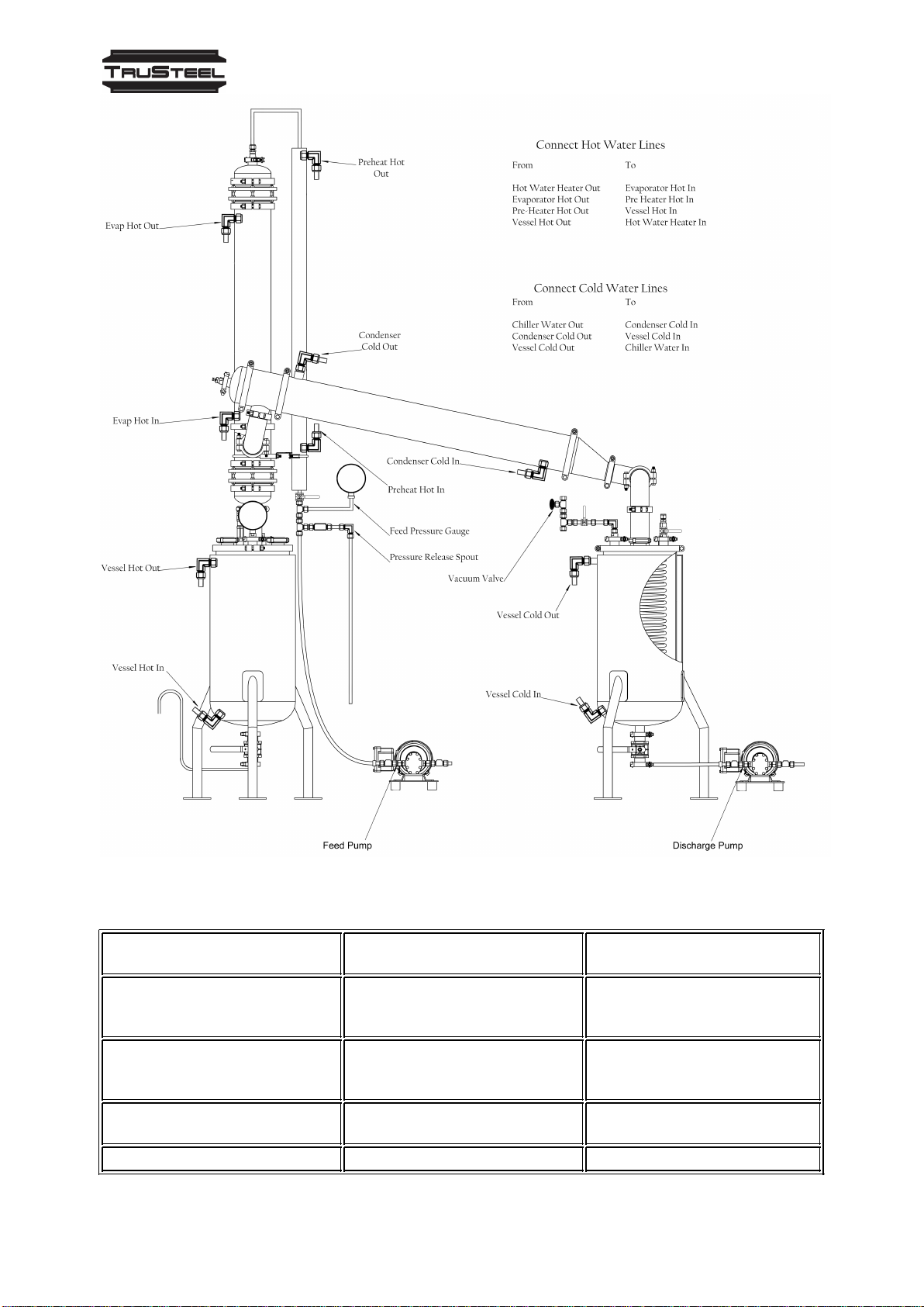
TheAutoVap15 system requires ancillary equipment to work with theAutoVap15 machine. The
main components to the system are:
1) TheAutoVap15, including (3) main heat exchangers [1 preheater, 1 evaporator, 1 condenser],
(2) pumps [feed pump, solvent discharge]
2) Cooling System – an HVAC chiller unit; includes Chiller Bypass Manifold
3) Heating System – Recirculating Hot Water Heater; includes Heater Manifold which includes an
inline water pump to recirculate water
4) Vacuum Pump
5) VFD Controller – Power supply and controls for feed pump and solvent discharge pump

AutoVap15 Operating Manual | |v. 1.2
4 / 23
AutoVap15 Operating Manual | |v. 1.2
5 / 23
SYSTEM REQUIREMENTS
WATER HEATING (Gas or
Electric)
Electric Water Heater minimum 18kw; minimum 8 gpm
flow rate; distilled water only; 1"
plumbing
Gas Water Heater minimum 200 BTU; minimum 8
gpm flow rate; distilled water only;
1" plumbing
COOLING minimum 5 tons of cooling; 1"
plumbing
VACUUM suggested: 6.1 cfm / 174 L/min

AutoVap15 Operating Manual | |v. 1.2
6 / 23
SECTION III: STARTUP PROCEDURES
In order to operate theAutoVap15 at correct capacity, the system requires the ancillary
equipment to be turned on and set at the correct parameters.
Operators shall follow the following procedures and verify all equipment is functioning properly
before proceeding to the next steps of operation
CHILLER STARTUP
START CHILLER
Procedure For First Time Operating Chiller
1. TURN ON DISCONNECT BREAKER
Locate chiller system and find the disconnect breaker (should be within 10 feet of the
chiller unit)
Lift the handle to the “ON” position
2. TURN ON CHILLER
Locate the red handle on the chiller unit
Turn the red handle to the “ON” position
The display on the Chiller should read “STANDY”
If it does NOT read “STANDY”, press and hold the snowflake button for 1-2 seconds
You will see a green snowflake on the digital display panel indicating the chiller is about to
start.
3. ALLOW CHILLER TO RUN 15-20 SECONDS
The compressor and fans will kick on and the chiller will start to bring down the
temperature to the programmed setpoint.
4. ALLOW TEMPERATURE TO DROP
Wait for the chiller to reach the ideal operating temperature for theAutoVap System (41-
44°F) before operating your AutoVap.
Procedure For Daily Startup
For daily startup, the chiller should already be on (breaker disconnect AND the red handle on the
chiller unit).
The Chiller should be in Standby mode at the start of every shift.
1. TAKE CHILLER OUT OF STANDBY MODE
Press and hold the “SNOWFLAKE” button for 1-2 seconds
You will see a green snowflake on the digital display panel indicating the chiller is about to
start.
2. ALLOW CHILLER TO RUN 15-20 SECONDS
The compressor and fans will kick on and the chiller will start to bring down the
temperature to the programmed setpoint.
3. ALLOW TEMPERATURE TO DROP
Wait for the chiller to reach the ideal operating temperature for theAutoVap System (41-
44°F) before operating your AutoVap.
NOTE: When shutting down the machine after operation it is very important to turn off the
machine properly. Press and hold the “snowflake” button and the chiller will go into standby
mode. Leave the chiller in standby and DO NOT TURN OFF RED HANDLE. It is important to let
the chiller complete its shutdown operation. Turning the Red Handle to “OFF” after operation can
damage chiller.

AutoVap15 Operating Manual | |v. 1.2
7 / 23
WATER HEATER STARTUP
MostAutoVap15 Systems from TruSteel are paired with a Hubbel Water Heater. For common
operating procedure, the Hubbel Water Heater is used throughout this startup procedure.
TruSteel also provides the manifold for the water heater which includes the water circulating
pump (normally a TACO brand pump).
START WATER HEATER
Procedure
1. TURN ON RECIRCULATING PUMP
Locate the power switch for the recirculating pump and power “on”.
2. TURN ON THE WATER HEATER
If the power to the water heater is disconnected, power on the breaker disconnect to the
water heater.
3. SET HEATER TEMPERATURE
For first time setup, you will need to set the temperature of the water heater. For daily use,
the temperature should be set at the ideal temperature already.
Simply press the up or down arrows on the water heater to set the temperature.
4. CHECK WATER HEATER DIAGNOSTICS (Electric Heater Models Only)
This is an important step to check each day of operation to be sure the flow is high
enough.
Press and Hold both the UP and DOWN arrows simultaneously for 1-2 seconds and
release.
You should not be in diagnostic mode.
Numbers will begin “flashing” on the water heater screen.
1st number is the heater temperature setpoint
2nd number is the temperature “OUT” of the heater to theAutoVap
3rd number is the temperature “IN”, back from theAutoVap
4th number is the “Flow Rate” in gallons/minute
The Flow Rate is very important
You must have a flow rate above 10 gallons/minute.
If the flow rate is below that, theAutoVap may not operate efficiently.
The flow rate should be between 5-10 GPM for optimal operation.
If the flow rate is below 5 gallon per minute you must refill the heater with water. Do this when the
before the heater is turned on. You must refill the heating system while the system cold.
VACUUM PUMP STARTUP
MostAutoVap15 Systems from TruSteel are paired with a Welch vacuum pump. For common
operating procedure, the Welch vacuum pump is used throughout this startup procedure.
START VACUUM PUMP
Procedure
1. POWER ON VACUUM PUMP

AutoVap15 Operating Manual | |v. 1.2
8 / 23
Locate the vacuum pump and verify it is plugged into an outlet.
Locate the power switch on the vacuum pump and switch to “ON”.
Note: Some facility setups could have a wall switch that controls power to the vacuum pump.
In this case, locate the wall switch and power on the vacuum pump.
#VERIFY VACUUM
You can verify the system is pulling vacuum from theAutoVap itself.
Open the vacuum valve on the vacuum manifold on theAutoVap. Open the vacuum fine tune
adjustment. There should be vacuum flow.
VARIABLE FREQUENCY DRIVE STARTUP
MostAutoVap15 Systems from TruSteel are paired with Lenze Variable Frequency Drives. If you
are operating anAutoVap15 withAuto Discharge for the Solvent Recovery, you will have 2
Variable Frequency Drives to turn on.
1. Turn on the VFD by locating the disconnect near the VFD or at the main breaker.
****Note: The VFD will now light up and display the speed of the motor measured in Hertz.
****Note: Hertz is measured from 0-60. This means at 0Hz the motor will not spin at all and at
60Hz the motor will spin at maximum speed.
****Note: Since hertz translates to how fast the motor will spin it also translates to how much
pressure it can create in theAutoVap feed system.
****Note: Starting Hertz is between 15-20
****Note: Operating pressure in the feed system 30 60- PSI
2. Press the up or down arrows to set start-up speed
3. ForAuto Discharge Only: Power on the VFD for AutoDischarge.
Before pressing Run on the VFD see the AutoVap Operating Procedures.
SECTION IV: OPERATING PROCEDURES
These are the suggested operating procedures by TruSteel to ensure your system runs efficiently and
recovers at least 15 gallons per hour. As you become more familiar with your system and your specific
material you are recovering, you may want to set your own parameters.
In any case, each step of this process should be closely reviewed, especially the cleaning cycle.
STEP 1: PULL VACUUM ON SYSTEM
AutoVap15 Operating Manual | |v. 1.2
9 / 23
1. Close all ball valves on theAutoVap: residue(crude) vessel, recovery (solvent) vessel,
below the preheater.
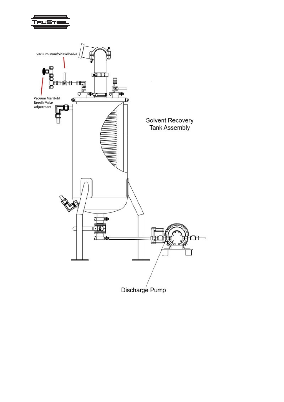
2. Find and Open the Vacuum Manifold Ball Valve.
3. Locate the vacuum gauge on the residue vessel.

AutoVap15 Operating Manual | |v. 1.2
10 / 23
4. Using the Vacuum Needle Manifold ValveAdjustment, adjust the vacuum pressure to
between 21-24 Hg.
****Note:Screwing in the needle valve (clockwise) will pull a deeper vacuum and unscrewing
(counterclockwise) will let more air into the system pulling less vacuum.
5. Double Check the following:
Water Heater is set between 130-190F
Chiller is set between 40-44F
Now theAutoVap is ready to start processing
****Note: the vacuum gauge reads 30in Hg to 15 PSI.
4. Using the Black needle valve on the vacuum manifold, adjust vacuum pressure bewtween
21-24in Hg.
****Note:Screwing in the needle valve (clockwise) will pull a deeper vacuum and unscrewing
(counterclockwise) will let more air into the system pulling less vacuum.
STEP 2: PRIME FEED PUMP
Before turning your feed pump on, it is important to first prime the feed pump by allowing the vacuum to
"pull" your tincture through the pump and up through the preheater.
AutoVap15 Operating Manual | |v. 1.2
11 / 23
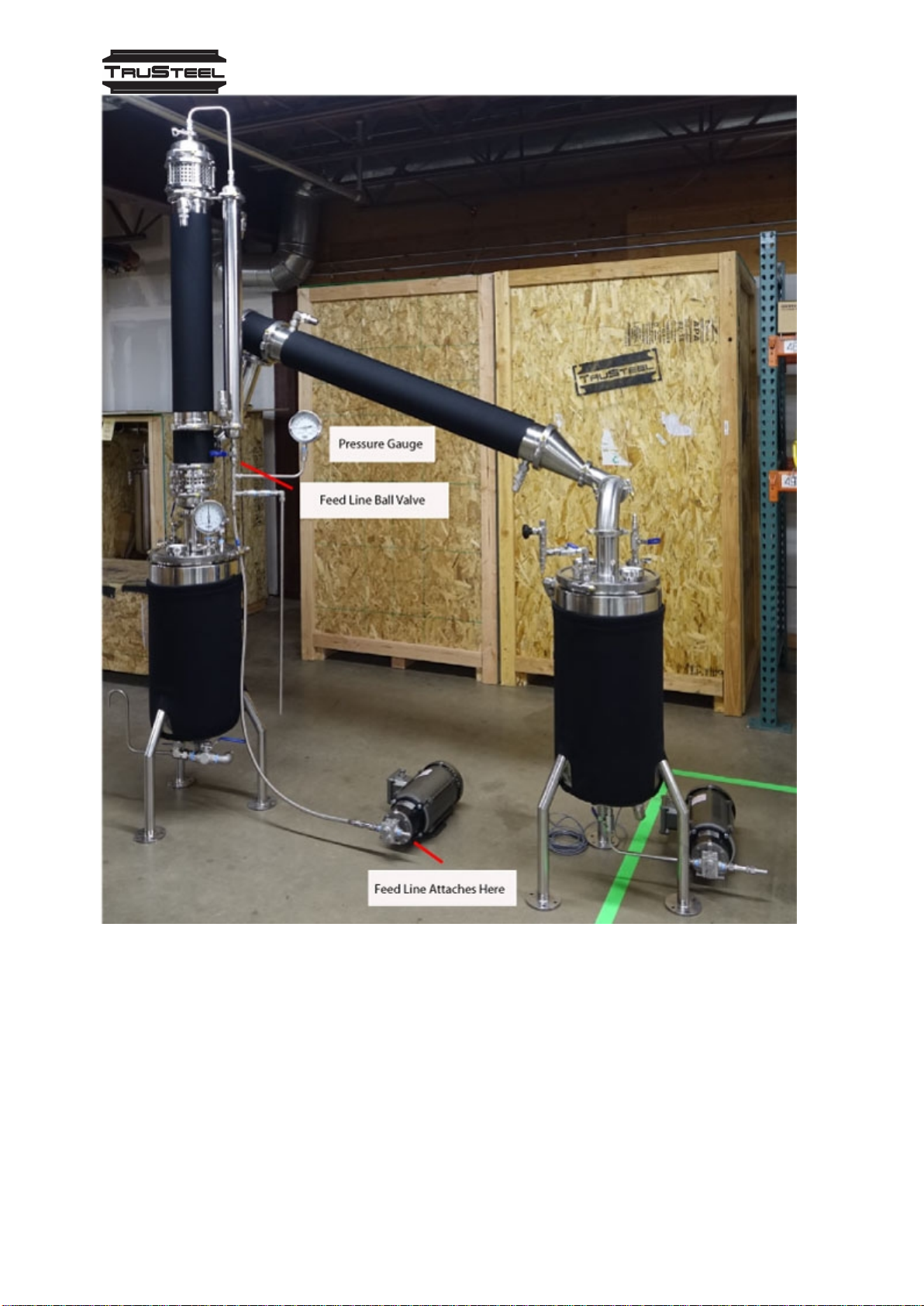
1. Locate the Feed Line and either attach it to your feed vessel or, using a dip stick, place the feed line
into your barrel.
2. Open the Feed Line Ball Valve
Tincture will now flow through the feed line and up through the preheater.
Note: After a 10-15 seconds the feed line and feed pump should be primed and the feed pump can be
turned on.
STEP 3: START FEED PUMP
Now that the feed pump is primed, you are now ready to start the feed pump and adjust the preheater
pressure.

AutoVap15 Operating Manual | |v. 1.2
12 / 23
1. Locate the Feed Pump Variable Frequency Drive Remote Control (if you are note using a remote you
can control the pump from the VFD)
2. Using the Up and Down arrows, adjust the speed of the pump. You will be referring to the Pressure
Gauge to determine the speed of the pump, but for starting, set the VFD at 15-20 Hz.
3. Press RUN on the VFD Remote. The feed pump will slowly "ramp up".
Note: As the feed pump is ramping up, it is filling up the preheater and release air pressure built.
This will take 1-3 minutes. Once the preheater is filled, you will start to see the pressure rise on
the pressure gauge located near the preheater.
The recommended operating PSI is42 PSI. This may be adjusted to as low as30 and ashigh as
60 PSI.
4. Adjust the feed pressure using the VFD Remote Control.
The AutoVap is now running and recovering your solvent. IMPORTANT: Be sure to monitor your feed vessel
to be sure you do not run out of tincture leaving the pump to run dry.
IMPORTNAT NOTE: There are 4 very important procedures to perform to ensure the longevity of your feed
pump:
1. Never run the pump dry: Always have tincture in your feed vessel while the feed pump is running.
2. Do not forget to open the preheater ball valve. Failure to open the valve can "dead head" the pump and
will compromise the pump.
3. Always prime your feed pump before turning on the VFD.
4. Always run cleaning cycles at the end of operating shifts.
STEP 4: SOLVENT DISCHARGE
As theAutoVap is running, you will be recovering solvent faster than you will be collecting residue.
IMPORTANT: If you are running theAutoVap15 Plus system, withAuto Discharge, you can skip this step.

AutoVap15 Operating Manual | |v. 1.2
13 / 23
To Discharge Solvent:
1. Set up Solvent Recovery Collection
Make sure you have you collection vessel either connected to the Recovery Tank, or place your
discharge line into a vessel
If using the silicone hose, connect one end of the silicone hose to the ball valve/hose barb assembly
on the bottom of the solvent recovery tank.
Connect or insert the other end to your solvent recovery collection vessel.
2. Turn off the Feed Pump
Press STOP on the VFD Remote Control
3. Close the Feed Line Ball Valve

AutoVap15 Operating Manual | |v. 1.2
14 / 23
4. Close the Vacuum Manifold Ball Valve
5. Release Vacuum from the entireAutoVap System
SLOWLY, open the vacuum release ball valve until the vacuum gauge reaches 0 HG.
CAUTION: You must open the valve SLOWLY while looking at the vacuumgauge. If
you open the ball valve too quicklyyou risk pulling over crude oil into your nicely
recovered solvent.
6. Close the Vacuum Release Ball Valve
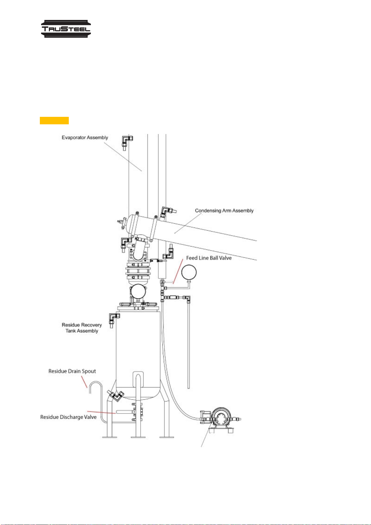
7. Open the Solvent Discharge Valve (See "4" on the figure above)
8. Locate theAir Chuck Assembly on the Residue Recovery Tank. The Ball Valve should be closed.
9. Attach an air compressor or N02 Generator to theAir Chuck Assembly [Located on the Residue Recovery
Tank]
If there is a pressure regulator on the compressor, set it between 5-15 PSI. You will not be using more than
5 PSI for this operation.
CAUTION: The Residue Recovery Tank is HOT, use caution when working near/around it.
10. Introduce Pressure to the system
Slowly open the Air Chuck Assembly ball valve to introduce pressure. Start with 1-3 PSI while monitoring
the pressure gauge.
WARNING: Do NOTpressurize the system above 15 PSI. If you do, the 15 PSI Pressure Relief Valve will
trigger. Be sure to have a collection vessel under the PRV blow off assembly.
A suggestion to ensure you do not over pressurize the system, is to toggle the Ball Valve on theAir Chuck
Assembly so that the system can only reach a maximum of 5 PSI.
The solvent should now be discharging from the Solvent Discharge Valve.
11. Verify the Solvent Recovery Tank is empty (view through sight glass)
12. Close the Ball Valve on theAir Check Assembly
13. Close the Solvent Discharge Valve.
STEP 4.1: RESTART THE SY STEM
Now that you have discharged your solvent, you can restart the system.
1. Pull Vacuum on System
Open the Vacuum Manifold Ball Valve
Wait until the vacuum pressure reaches the desired setpoint (21-24 HG). You may need to adjust the
Vacuum Manifold Needle ValveAdjustment
2. Open the Feed Line Ball Valve
3. Start the Feed Pump
Press "Run" on the VFD Remote Control
AutoVap15 Operating Manual | |v. 1.2
15 / 23
STEP 5: RESIDUE DISCHARGE
You will continue to repeat STEP 4: SOLVENT DISCHARGE while monitoring your Residue Recovery
Vessel. When the Residue Recovery Vessel is filled to your desired capacity (be sure not to overfill), you
are ready to discharge the residue material.
Note: AutoVap1 Plus will also need to manually discharge residue
NOTE: This process is similar to STEP 4: SOLVENTDISCHARGE, except you will be opening the Residue
Discharge Valve
WARNING: When removing the crude oil be very CAREFUL as it is EXTREMELY HOT.
1. Stop Feed Pump (Press "STOP" on VFD Remote Control)
2. Close the Feed Line Ball Valve (see diagram above to locate Feed Line Ball Valve)

AutoVap15 Operating Manual | |v. 1.2
16 / 23
3. Release Vacuum from System
Slowly open the Vacuum Release Ball Valve (similar to Solvent Discharge) and monitor the vacuum
pressure goes down to 0 HG.
4. Close Vacuum Release Ball Valve.
5. Prepare residue collection vessel under Residue Drain Spout.
6. Open Residue Discharge Valve
7. Locate theAir Chuck Assembly on the Residue Recovery Tank. The Ball Valve should be closed.
8. Attach an air compressor or N02 Generator to theAir Chuck Assembly [Located on the Residue Recovery
Tank]
If there is a pressure regulator on the compressor, set it between 5-15 PSI. You will not be using more than
5 PSI for this operation.
CAUTION: The Residue Recovery Tank is HOT, use caution when working near/around it.
9. Introduce Pressure to the system
Slowly open the Air Chuck Assembly ball valve to introduce pressure. Start with 1-3 PSI while monitoring
the pressure gauge.
WARNING: Do NOTpressurize the system above 15 PSI. If you do, the 15 PSI Pressure Relief Valve will
trigger. Be sure to have a collection vessel under the PRV blow off assembly.
A suggestion to ensure you do not over pressurize the system, is to toggle the Ball Valve on theAir Chuck
Assembly so that the system can only reach a maximum of 5 PSI.
The residue should now be discharging from the Residue Drain Spout.
10. Verify the Residue Tank is empty (view through sight glass)
12. Close the Ball Valve on theAir Check Assembly
13. Close the Residue Discharge Valve.
You will repeat this step each time your residue fills, or you are done running a batch.
STEP 6: CLEANING CYCLE
The cleaning cycle is a very important step in your solvent recovery process. Following this cleaning
procedure will ensure yourAutoVap will continue to run at full efficiency and it is will increase the longevity of
your equipment, especially the feed pump.
Leaving the feed pump to sit with tincture material to dry will surely cause your pump to fail. The material
you are processing through yourAutoVap contains fats and sugars. These materials collect as a residue
throughout the entire feed/residue side of yourAutoVap.
The Clean Cycle Order is: Solvent - Distilled Water - Solvent
This means, once you have discharged all your material, you will run clean solvent through theAutoVap,
then you will run distilled water (this is for the sugars), and then run some more clean solvent (to remove the
water residue)
These are the steps to run your cleaning cycle:

AutoVap15 Operating Manual | |v. 1.2
17 / 23
1. Discharge all residue material from yourAutoVap
You want to start your cleaning cycle with the AutoVap empty in both, the residue and solvent side.
See STEPS 4 and 5 for instructions how to discharge your material.
2. Prepare Clean Solvent (4-8 Gallons)
Prepare clean solvent just as you would your tincture, for normal processing.
3. Run the clean solvent through your system. About 1-2 gallons.
During this phase, you are running the system at normal operating parameters: Heater set at around
190F, Chiller set at ~40F, Vacuum set at 22HG, Pressure set around 42 PSI
When you have run about 2 gallons through the system at these parameters, proceed to the next step.
4. Release Vacuum on the system
Close the Vacuum Manifold Ball Valve and SLOWLY open the Vacuum Release Ball Valve
Verify the vacuum level drops to 0 HG
NOTE: This now ensures that the clean solvent will now completely clean the residue side of theAutoVap.
The condenser side is already clean.
5. Run the remainder of the clean solvent through the system with these parameters (no vacuum).
Monitor the lower sight glass on the Residue Falling Film. The solvent should be clear by the end of
running all your clean solvent.
6. Drain the Residue Vessel
Follow the process in STEP 5 to drain this "dirty" solvent.
NOTE: This solvent is really diluted tincture that you can store/save and run through theAutoVap another
time, if your business model allows for that.
7. Prepare Distilled Water (3-6 Gallons)
This part of the cleaning cycle is VERY IMPORTANTand should NOT BE OVERLOOKED. The distilled
water will help remove any sugar residue that has collected throughout yourAutoVap.
8. Release vacuum from system. Set Vacuum Pressure to 0 HG
9. Run the distilled water through your system. This is the same procedure as running tincture or solvent
through theAutoVap.
NOTE: With the vacuum set to 0 HG, you should not have water reaching the solvent recovery tank; it
should all be "raining down" into your residue tank.
10. Drain all water from the system. Residue Tank and Solvent Recovery Tank.
NOTE: You will most likely NOT want to save this water
11. Prepare more clean solvent (1-2 gallons)
12. Run this solvent through the system. This will remove any traces of the distilled water in your system.
13. Drain this solvent. You most likely will NOTwant to keep this solvent as it is contaminated with water,
unless you have a process to remove water from your solvent.
The AutoVap is now clean and ready for the next shift.
OPERATING SUGGESTIONS AND TIPS
The AutoVap15 has been in operation for quite a few years now and there have been many various ways of
running it depending on each customers specific process.
Here we have compiled a list of some suggestions and tips to ensure you are getting the most out of your
AutoVap15 Solvent Recovery.
1) DO NOToverlook your cleaning process.
Cleaning your system after every shift (8-10 hours of continuous operation) is extremely important.

AutoVap15 Operating Manual | |v. 1.2
18 / 23
Remember the Solvent-Distilled Water-Solvent cleaning process. The distilled water is important for
dissolving and removing the sugar residue.
2) Parameters: Feed Pressure and Vacuum
There is no required parameter for either the feed pressure or vacuum pressure. However, there are some
parameters to stay within.
Feed Pressure Min - Max: 30-65 PSI
It has been tested that running the system at 42 PSI should recover at least 15 gallons per hour.
Running the system slower may decrease the recovery rate, but will leave you with a "thicker" residue
material with less solvent in the final product.
Running the system faster will leave your material a bit "soupier" but will increase your solvent recovery
rate.
Vacuum Pressure Min-Max: 20-25 HG
It has been tested that running the system at 22 HG is an efficient, safe operating parameter.
You can increase your vacuum pressure, but be aware that this can "pull" your residue material over into
your solvent recovery side and taint your clean solvent.
Pulling deep vacuum can also cause vapors to carry into your vacuum pump, which can cause vacuum
pump failure over time.
3) Heat and Cold Temperatures
The temperature you set your Water Heater at will depend on what solvent you are recovering. You can
do some research to check the boiling point of the solvent used, along with the latent heat of evaporation.
This will determine how much heat you should apply.
Keep in mind that with vacuum, the boiling point of solvents decreases. You can research the boiling
point of solvents under vacuum.
For Ethanol, is has been tested that anywhere from 190F-194F is ideal for efficient evaporation.
The temperature of your chiller should be set anywhere from 34F-42F. Again, you will want to do some
research about how the solvent you are using condenses.
4) Water Heater Flow Rate
The flow rate of the water heater is extremely important to ensure yourAutoVap is performing at full
efficiency.
For theAutoVap15, you should have a flow rate of at least 5 gallons per minute. The higher the flow rate
the better. With some recirculating pumps, you may be able to see around 10-15 gallons per minute.
The flow rate may be determined by a few variables:
1. The capacity of your recirculating pump
2. The length and flow of your plumbing line supplying theAutoVap and returning to the Water Heater
3. Water pressure. This closed loop system can, in fact, lose water pressure over time and may need to
be re-primed.
5) Never Run Your Pump Dry
Be sure to monitor your tincture material being fed into the system. You never want to have the feed
pump running dry. This can cause your pump to fail and will cost you time and money to replace.
NOTE: The TruSteel warranty does NOTcover pumps that were run dry.
6) Never dead head your pump
Always remember to open the Feed Line Ball Valve when running yourAutoVap. Failing to open the Feed
Line Ball Valve could "dead head" the pump and cause failure.
Again, TruSteel is does not warranty pumps that were improperly run, such as dead heading due to
operator error.
7) Auto Discharge on Recovery Vessel
HavingAuto-Recovery on the Solvent Vessel is a great convenience. You will not have to stop the
AutoVap to discharge your material.
Great news, any AutoVap15 Basic can be upgraded to anAuto Discharge. Contact TruSteel for pricing
and more information.

AutoVap15 Operating Manual | |v. 1.2
19 / 23
8) Purge Residue Material
If you have the time, you can actually use theAutoVap15 Residue tank as a purging tank. After filling
your residue tank with "crude" (full is around the 3/4 mark), you can stop the feed and just pull very deep
vacuum on the system. You can purge your material for 15-30 minutes. This will leave you with a thicker
final product with less solvent left.
9) Feed Tank (feed from bottom)
We suggest using a feed tank that feeds from the bottom. A bottom fed tank uses gravity to help feed the
material which will eliminate any air pockets in the feed line. This will ensure you are not causing a large air
pocket with can cause cavitation at the pump and cause it to run dry.
A conical fermenter tank works well for this application.
10) Extra Pump
It is highly suggested you purchase either an extra pump or a rebuild kit. Pumps can fail from either
operator error or from natural deterioration over time. You can decrease downtime by having an extra pump
on hand instead of relying on TruSteel to have one in stock and have to rush delivery (expensive shipping
costs).
SECTION V: TROUBLESHOOTING
1) Falling Film Heat Issues (Soupy Material)
ISSUE: The evaporator seems to not be evaporating efficiently and it is "raining down" solvent
filled residue into the residue collection tank.
POSSIBLE CAUSE: This is most likely due to a low flow rate from your water heater. Please
check the flow rate at your water heater. If it is at 5 gallons per minute or lower, you will want to
add more water into the closed loop system.
Check your water heater temperature. What is the temperature in? What is the temperature
out? In the electric water heater models you can check the diagnostics on the water heater
(Temp in, Temp out, Flow Rate)
After verifying the water heater is working properly and the flow rate is up over 5 gpm, run the
system again and see if your recovery has improved.
2) Feed Pressure Issue
ISSUE: I cannot get the feed pressure up to 42 PSI, it only reaches around 20 PSIand then
drops.
POSSIBLE CAUSE: You feed pump could be starting to fail. Pumps do deteriorate over time.
This is NOT covered under the TruSteel Warranty. We suggest to either have an extra pump on
hand, or purchase a pump rebuild kit.
3) Checking for Vacuum Leaks
ISSUE: TheAutoVap is not holding vacuum. The vacuum is dropping quickly.
POSSIBLE CAUSE: There could be a small leak in one of the connections (clamps) in the
system. With the system empty of processing material, you can perform a pressure test on all
clamp connections.
POSSIBLE CAUSE 2: Verify all all clamps are completely closed
4) AutoDischarge Not Discharging
ISSUE: AutoDischarge was discharging normally and now it is not discharging.
POSSIBLE CAUSE: The check valve after the solvent recovery pump could be stuck. Try
removing the check valve and performing a blow test to confirm that the check valve is working.

AutoVap15 Operating Manual | |v. 1.2
20 / 23
5) Inconsistent Spray Pattern
ISSUE: The spray pattern at the top of the falling film doesn't seem like an even spray.
POSSIBLE CAUSE: The spray nozzle could be slightly clogged. Remove the spray nozzle and
clean it with solvent, then water, and then solvent.
6) Solvent in Vacuum Pump
ISSUE: There is a lot of solvent coming through the vacuum pump.
POSSIBLE CAUSES: You are either pulling too deep of vacuum on the system (more than 24
HG), or the chiller is not actually cooling the condenser arm (verify the chiller is working).
SECTION VI: OPERATION & SAFETY INFORMATION
Operators of the AutoVap™ are required to follow all safety protocols and instructions. The user
and operator are responsible for any injuries to person or property while using this equipment
and are advised to follow procedures as detailed in this operating manual.
Only trained professionals with the complete understanding of the equipment- and full
understanding of the risks associated with the use of alcohol, should be operating this
equipment. The evaporating and condensing of alcohol has inherent risks. Any misuse of this
equipment can result in severe injury, including but not limited to death, disability and property
damage.
Safety Warning Definitions
·The DANGER notice indicates and immediate hazard which, if not avoided, will result in
serious injury or death.
·The WARNING notice indicates a hazardous situation which, if not avoided, can result in
serious injury or death.
·The CAUTION notice indicates a potentially hazardous situation which, if not avoided, may
result in minor or moderate injury, and or damage to the equipment. Do not
proceed beyond a CAUTION notice until indicated conditions are rectified.
It is the operatorʼs sole responsibility to use the equipment in a safe manner. Operators
assume all risk associated with the use of this equipment and agrees that the equipment
is to onlybe used for lawful purposes.
DANGER This equipment uses high-proof alcohol. Alcohol is a flammable liquid. Improper use
may cause alcohol to discharge, resulting in an unsafe environment. Use
proper ventilation, personal protective equipment, and appropriate detectors.
DANGER Inhalation of highly concentrated alcohol vapors may affect the central nervous
system. This is characterized by nausea, headache, dizziness, unconsciousness and/ or
comma. It may cause respiratory tract irritation and a narcotic effect. Please read MSDS for
further safety instructions.
WARNING Operators must follow all precautions and safety guidelines to ensure their own
safety and the protection of property.
WARNING Always visually monitor fill levels, tanks, valves, seals and hoses for leakage. While
the system is protected with pressure relief valves, proper monitoring should be take to ensure
Table of contents
Other TruSteel Industrial Equipment manuals


