Truweld TWE-SC1950 User manual

TRU‐WELDEQUIPMENTCOMPANY
6400N.HoneytownRoad
Smithville,Ohio44677
(330)725‐7744Phone
(330)669‐2473Fax
http://truweldstudwelding.com
Operations Manual
TheSC1950isafullyintegratedstudweldingsystemwithtwodigitalcon‐
trolsfortimeandcurrent.Thesystemwasdesignedtobeaperfectfitfor
shopuse,excellingatsmall‐tomedium‐sizeddiameterstuds,allinacom‐
pact,affordablepackage.
TWE - SC1950
Stud Welding System
Version1.002/06/2013

2
TRU‐WELDEQUIPMENTLIMITEDWARRANTY
AllgoodsproducedbyTruweldEquipmentshallbewarrantedagainstdefectsincludingworkmanshipandcomponents.Nootherwar‐
rantieswhetherexpressed,verbal,orimpliedwillapply.Warrantiesonlyapplytotheoriginalequipmentpurchaser.
WarrantyclaimswillbelimitedtoeitherrepairorreplacementofthedefectivematerialsbyTruweldEquipment.AttheoptionofTru‐
weldEquipmentthelocationofwherethewarrantyevaluationandrepairsaremadewillbedetermined.Allwarrantyclaimitemsre‐
turnedtoTruweldEquipmentwillbeatthecustomer’sexpense.AttheoptionofTruweldEquipmentthedefectwilleitherberepaired
orreplaced.NoticemustbeprovidedtoTruweldEquipmentofawarrantydefectwithin30daysthatthedefectorfailureisincurred.
Warrantiesarenottransferable.
Thiswarrantydoesnotapplyforequipmentwhichisusedimproperlyinanyfashionincludingbutnotexclusivetothefollowing:
Equipmentwhichhasbeenmodified
Equipmentwhichhasnotbeeninstalledproperly
Equipmentwhichhasbeenusedforpurposesotherthanwhichithadbeendesigned
Equipmentwhichhasnotbeenproperlymaintained
Equipmentwhichwascontinuedtobeusedafteradefecthadbeenfound
Equipmentwhichwasdamagedinanyway
TruweldEquipmentwillneverbeliableforconsequentialdamages,loss,orexpenseoccurringdirectlyorindirectlyfromtheuseofthe
equipmentcoveredinthiswarranty.
Allcables,cablesetsandconnectorsarenotwarranted.
Two(2)yearwarrantyperiodfromdateofpurchase
TWE250PowerSupplySC1900PowerSupply
TWE321PowerSupplySC1950PowerSupply
TWE375PowerSupplySC2400PowerSupply
SC900PowerSupplySC2402PowerSupply
SC1400PowerSupplySC2420PowerSupply
SC1450PowerSupplySC3400PowerSupply
SC1600PowerSupplySC3402PowerSupply
SC1650PowerSupply
One(1)yearwarrantyperiodfromdateofpurchase
TWESPCPowerSupplies
TWP‐2PowerSupply
NinetyDay(90)warrantyperiodfromdateofpurchase
(Excludingcablesandconnectors)
TWE70000HDArcstudgun
TWE18500MDArcstudgun
TWE19000LDArcstudgun
TWEGCDstudgun
TWEHDGHeavyDutyCDstudgun

3
TableofContents
SectionDescriptionPage
1.0Cover1
1.1ProductWarranty2
2.0TableofContents3
3.0CompanyProfileandProductInformation4
4.0SafetyPrecautions
4.1SafetyPrecautions‐SymbolsandDescription5
4.2SafetyPrecautions‐ElectricShock6
4.3SafetyPrecautions‐WeldingSparks 7
5.0ProductSpecifications8
6.0SC1950SetupandInstallation
6.1SC1950SetupandInstallation‐InitialSteps9
6.2SC1950SetupandInstallation‐PrimaryPower10
6.3SC1950SetupandInstallation‐GroundCableConnections11
6.4SC1950SetupandInstallation‐ControlCableConnections12
7.0SC1950Operations‐StudGunSetup
7.1StudGunSetup‐InitialSteps13
7.2StudGunSetup‐LiftAdjustment14
7.3StudGunSetup‐PlungeAdjustment15
7.4StudGunSetup‐CableConnections16
8.0SC1950Operations‐Settings
8.1SC1950Operations‐UnitPower/DiagnosticLights17
8.2SC1950Operations‐SettingTimeandCurrent18
8.3SC1950Operations‐SettingJobCounter19
9.0SC1950Operations‐Welding
9.1StepbyStep20
9.2TipsandSuggestions21
9.3WeldInspectionandAdjustments22
10.0Troubleshooting 23,24
10.1Troubleshooting‐ChartA25
10.2Troubleshooting‐ChartB26
11.0PartsandAccessories27

4
CompanyandProductInformation
CompanyProfile
Tru‐WeldStudWeldinghasbeenmakingweldstudssince1959,andsince1970wehavebeenpro‐
ducingourownlineofhigh‐qualitystudweldingequipment.Tru‐WeldislocatedinMedina,Ohioand
hasproductandequipmentdistributorsacrossthenation.Tru‐WeldEquipmentCompany(TWE)of‐
fersafulllineofDrawn‐ArcandCapacitorDischarge(CD)studweldingequipment,replacementparts,
andaccessories.
OurexperiencedManagementandStaffiscommittedtoprovidetheutmostinqualityandservicein
everystepofourproduction,whileremainingcompetitiveinthemarketplace.Itisourgoaltomeet
ourcustomer'sneedsmoreeffectivelythanourcompetitorsthroughaprocessofcontinuousquality
improvement.Ourlong‐standingrelationshipwithourcustomers'andsuppliers'isourkeytocontin‐
uedsuccessandgrowth.Ifwecanbeofanyfurtherassistancetoyouandyourcompany,pleasedonot
hesitatetocontactus.
ProductInformation
TheSC1950isafullyintegratedstudweldingsystemwithtwodigitalcontrolsfortimeandcurrent.
Thesystemwasdesignedtobeaperfectfitforshopuse,excellingatsmall‐tomedium‐sizeddiame‐
terstuds,allinacompact,affordablepackage.
Features:
♦ Smootharccurvetargetedforsmalltomediumsizeddiameterstuds
♦ EnhancedDutyCycleproductionrequirements
♦ Capableofupto100feetof4/0weldingcableaccommodatesalargevarietyofworkstationlay‐
outs
♦ Steplesstimeandcurrentcontrolallowforinfinitesettingsforfine‐tuningtheweldingoutput
♦ StudJobCounterthatcanberesetforeveryjob
CompletesystemIncludes:
1800Amppowersupply,TWE17000HeavyDutystudgun,35feetof4/0combocableand25feetof
4/0groundcable.

5
Safetyiseveryone’sresponsibility.TRU‐WELDdesignseverymachinewithsafetyinmind,anda
safeworkenvironmentdependslargelyonyou.
Donotinstall,operate,orrepairthisequipmentwithoutcarefullyreadingthismanualandobserv‐
ingallofthesafetyprecautionsmentioned.Ifthereisaquestion,askyoursupervisor!
SafetySymbols
Everyefforthasbeenmadetoprotecttrainedoperatorsfrominjuryorunnecessaryrisk.Certain
symbolsareusedthroughoutthismanualtocallattentiontosafety‐relatedinformationandin‐
struction.Thesafetysymbolsinthismanualhavethesemeanings:
ThissymbolindicatesDangerousSituations.Whenthissymbolisusedinthismanual,
deathorseriousbodilyharmispossibleorprobableifthecorrespondingpreventative
measuresarenottaken.Operatorsmusttakecautioninthemethodandmannerof
handlingorusingthemachinewhenthissymbolisdisplayed.
SafetyPrecautions
Donotinstall,operate,orrepairtheSC1950weldingequipmentwithoutreadingthismanualand
allsafetyprecautionsstatedwithin!
Thismachinewasdesignedandbuiltwithoperatorsafetyinmind,butsafetybeginswithyou!
Everyefforthasbeenmadetoprotectthetrainedoperatorfrominjury.Pleasebecomefamiliar
withtheinformationinthismanualtominimizetheriskofshockorinjury.
STUDWELDINGCANBEHAZARDOUS.ALWAYSPROTECTYOURSELFANDOTHERS
FROMPOSSIBLEINJURYORDEATH.KEEPCHILDRENAWAY.
Operatorswhohaveapacemakershouldconsultwiththeirphysicianbeforeoperatingstudweld‐
ingequipment.
FUMESandOXYGENDEPLETION
♦ Onlyweldinareasorroomswhereadequateventilationofweldgasesispossibleandwhere
thereisnotfire,smokeorexplosionhazards.
♦ Whenworkinginaconfinedspacealwayshavetrainedsupportpersonnelnearby.
♦ Weldingfumesandgasescandisplaceairandlowertheoxygenlevelcausinginjuryordeath.Be
surethebreathingairissafe.
♦ Donotweldinlocationsneardegreasing,cleaning,orsprayingoperations.Theheatandraysof
thearcscanreactwithvaporstoformhighlytoxicandirritatinggases.
♦ Donotweldoncoatedmetals,suchasgalvanized,lead,orcadmiumplatedsteel.Thecoating
mustberemovedfromtheareatobewelded.Coatingsandmetalscontainingaboveelements
cangeneratetoxicfumeswhenheatedtoweldingtemperature.
StudWeldingSafetyPrecautions

6
ELECTRICSHOCK
Electricshockcaninjureorkill!
Precautionarymeasuresmustbetakentoprovidemaximumprotectionagainstelectri‐
calshock.
♦ Donottouchliveorenergizedelectricalpartsorstoremetallicobjectsnearpower.
♦ Groundtheworkormetaltobeweldedtoagoodelectrical(earth)ground.
♦ Donotleaveanenergizedmachineunattended.
♦ Neverworkinwetclothing,glovesorfootwear.
♦ Insulateyourselffromworkandgroundusingdryinsulation.Makecertaintheinsulationis
largeenoughtocoveryourfullareaofphysicalcontactwithworkandground.
♦ Inspectallsystemcomponents,protectiveequipment,cables,connectorsandgaslinesprior
tooperatingequipment.Neverusecablesthatarelongerthannecessary.
♦ Whentestingaliveunit,usetheone‐handmethod.Donotputbothhandsinsideoftheunit.
Keeponehandfree.
♦ Disconnectinputpowerconductorsfromde‐energizedsupplylinebeforemovingawelding
powersource.
♦ Alwaysbesuretheworkcablemakesagoodelectricalconnectionwiththemetalbeing
welded.Theconnectionshouldbeascloseaspossibletotheareabeingwelded.
♦ TurnOFFweldingpowersourcebeforeservicingunlesstheprocedurespecificallyrequiresan
energizedunit.
♦ Nevertouchtheenergizedstudorgunbeforedischargingthestudtoground.
♦ Neverusethepowersourcetoprovideheatforthawingfrozenpipes.
ARCRAYSandEYEPROTECTION
Arcrayscaninjureeyesandburnskin.
Arcflashesarepainful.
♦ Useashieldwiththeproperfilterandcoverplatestoprotectyoureyesfromsparksandthe
raysofthearcwhenweldingorwhileobservingopenarcwelding.
♦ Useprotectiveclothingspecificallyintendedforworkwithweldingequipment.Itshouldbe
madeofdurableflame‐resistantmaterialtoprovideampleprotectionfromthearcrays.
♦ Protectothernearbyworkerswithsuitable,non‐flammablescreening.Cautionotherworkers
nottowatchthearcnorexposethemselvestothearcraysortohotspatterormetal.
StudWeldingSafetyPrecautions

7
StudWeldingSafetyPrecautions
WELDINGSPARKS
Heatfromflamesandarcscanstartfires.Hotslagorsparkscanalsocausefiresand
explosions.
Removeallcombustiblematerialsfromtheworkareaorcoverthesematerialswithaprotectivenon‐flammabletarp.
Combustiblematerialsincludewood,fabrics,sawdust,liquidandgasfuels,solvents,paintsandcoatings,paper,etc.
Hotsparksorhotmetalcanfallthroughcracksorcrevicesinfloorsorwallopeningsandcauseahiddensmoldering
fire.Makecertainthatsuchopeningsareprotectedfromhotsparksandmetal.
ELECTRICandMAGNETICFIELDS
ElectriccurrentflowingthroughanyconductorcauseslocalizedElectro‐MagneticFields(EMF).Weldingandcutting
currentcreatesEMFaroundweldingcablesandweldingmachines.
♦ Operatorshavingpacemakersshouldconsulttheirphysicianbeforewelding.EMFmayinterferewithsometype
ofpacemakers.
♦ ExposuretoEMFmayhaveotherhealtheffects,whichareunknown.
♦ OperatorsshouldusethefollowingprocedurestominimizeexposuretoEMF:
♦ Routetheworkcablestogether.Securethemwithelectricaltapewhenpossible.
♦ Nevercoiltheworkcablearoundanypartofyourbody.
♦ Donotplaceyourbodybetweentheworkcables.Routecablesonthesamesideofyourbody.
♦ Connecttheworkcabletotheworkpieceascloseaspossibletotheareabeingwelded.
♦ Keepweldingpowersourceandcablesasfarawayfromyourbodyaspossible.
♦ Electromagneticfieldscanirrevocableerasemagneticdatacarriers(computermemory,creditcards,securityID
cardsordatastoragediskettes).
♦ Electromagneticfieldsmaymagnetizeanddamagewatchesorsimilardigitaldevices.
PROTECTYOURSELFandOTHERS!
Somewelding,cutting,andgougingprocessesarenoisyandrequireearprotection.Thearc,likethesun,
emitsultraviolet(UV)andotherradiationandmayinjureskinandeyes.Hotmetalcancauseburns.
Trainingintheproperuseofweldingprocessesandequipmentisessentialtopreventaccidents.
♦ Alwayswearsafetyglasseswithsideshieldsinanyworkarea.Inconjunctionwitheyeprotection,weldinghel‐
metsorfaceshieldsarealsorequired.
♦ Useafaceshieldfittedwiththecorrectfiltercoverplatestoprotectyoureyes,face,neck,andearsfromsparks
andraysofthearcwhenoperatingorobservingoperations.Warnbystandersnottowatchthearcandnotto
exposethemselvestotheraysoftheelectricarcorhotmetal.
♦ Wearflameprooftypegloves,heavylong‐sleeveshirt,cufflesstrousers,andaweldinghelmetorcapforhairpro‐
tection,toprotectagainstarcraysandhotsparksorhotmetal.Aflameproofapronmayalsobedesirableaspro‐
tectionagainstradiatedheatandsparks.
♦ Hotsparksormetalcanlodgeinrolledupsleeves,trousercuffs,orpockets.Sleevesandcollarsshouldbekept
buttoned,andopenpocketseliminatedfromthefrontofclothing.

8
Features
♦ Smootharccurvetargetedforsmalltomediumsizeddiameterstuds
♦ EnhancedDutyCycleproductionrequirements
♦ Capableofupto100feetof4/0weldingcableaccommodatesalargevarietyofworkstation
layouts
♦ Steplesstimeandcurrentcontrolallowforinfinitesettingsforfine‐tuningtheweldingoutput
♦ StudJobCounterthatcanberesetforeveryjob
♦ On‐DemandFanthatcyclesonandoffwhenneeded.
WeldRange1/4”to7/8”Consistentweldingregardlessofstuddiameter.
DutyCycle1/4”thru3/8”
1/2”
5/8”
3/4”
7/8”
Unlimited
22to24perminute
9to10perminute
4to5perminute
3to4perminute
DimensionsHeight
Width
Length
Weight
22”(559mm)
25”(635mm)
30”(762mm)
445Lbs.(202kg)
InputVoltages 380/400VAC3Phase50Hz
FusingRequirements(Slowacting)400/60Amps
SC1950ProductSpecifications
**Specificationsaresubjecttochangewithoutpriornotification.

9
SC1950SetupandInstallation
InitialSteps
Onlyqualifiedpersonnelshouldperformthisinstallation.
♦Turntheinputpoweroffatthedisconnectswitchorfuseboxbeforeworkingonthewelder.
♦Donottouchelectricallyhotparts.
ThissectionprovidesdetailedinstructionsfortheproperinstallationoftheTWESC1950.Itis
recommendedthattheseinstructionsbefollowedcarefullytoallowforthebestpossibleoperat‐
ingenvironment.
HandlingandUnpackingtheWelder
Immediatelyuponreceiptofthewelder,inspecttheshipmentforanydamageandnotifythe
carrierofsuchdamagebeforeacceptingdelivery.Theninspectwelderfordamagewhichmay
haveoccurredintransit.Afterremovingthecomponentsfromtheshippingcontainer(s),check
thecontainerforanylooseparts.Removeallpackingmaterials.Visuallycheckallairpassagesof
powersourceforanypackingmaterialsthatmayobstructairflowthroughthewelder.Ifthe
equipmentisnotbeinginstalledimmediately,storeitinaclean,dry,well‐ventilatedareauntilin‐
stallation.
SelectingaLocation
Thelocationofthepowersourceshouldbecarefullyselectedtoensuresatisfactoryanddepend‐
ableservice.Choosealocationrelativelyclosetoaproperlyfusedsourceofelectricalpower.Use
careagainsttopplingoverifthemachineisplacedonatiltedsurfaceorplane.Itisimportantthat
themachinebelocatedinanopenareawhereaircancirculatefreelythroughthefrontandrear
openings.Ifspaceisatapremium,leaveatleast1foot(300mm)ofclearancebetweentherear
ofthepowersourceandwallorotherobstruction.
ElectricalInputRequirement
Theweldingpowersourceisdesignedtobeoperatedfromthree‐phase,50Hertz,ACpowersup‐
ply.Consultyourlocalelectricalutilityifyouhaveanyquestionsontheelectricalsystematthe
presentinstallationsite.TheSC1950shouldbeoperatedfromaseparate,fusedorcircuit‐breaker
protectedcircuit.

10
SC1950SetupandInstallation
PreparingtheUnitforPrimaryPower
Onlyqualifiedpersonnelshouldperformthisinstallation.
♦Turntheinputpoweroffatthedisconnectswitchorfuseboxbeforeworkingonthewelder.
♦Donottouchelectricallyhotparts.
RemovethetopcoveroftheSC1950.Alloftheconnectionsthatwillneedtobemadeareaccessi‐
blewiththetopcoverremoved.
PrimaryPowerCable
♦ RoutethePrimaryPowerCablethroughthePowerInletHoleinthetopleftcorneronthe
backsideofthewelder.
♦ Connectthepowerleads(Black,White,Red)totheL1,L2,andL3connectorsasshowninFig‐
ure1.Firmlytightenscrewsthatholdthepowerleadsinplace.
♦ Attachthegroundwire(Green)tothegroundlugofasshowninFigure1.
♦ OncethePrimaryPowerCableisconnected,tightenPowerCableClamponthebackofthe
welder,holdingthepowercablefirmlyinplace(seeFigure2).Allowenoughplayincableso
thatthecableisfreefromanyobstructionsanddoesnotlayacrossjumperboard.
PowerConnections
GroundConnection
Figure1Figure2
PowerInlet
(inbackofunit)

11
SC1950SetupandInstallation
GroundCableConnections
♦ TheSC1950isequippedwithonegroundcableconnectionlocatedinthefrontofthewelder
(liftaccesspanel).
♦ TightengroundcabletowelderandsecureotherendtoworksurfaceusingtheGroundCable
Clamp(seeFigure2).
AccessPanelGroundconnection
Figure1‐FrontofSC1950
GroundCableLug(towelder)
GroundCableC‐Clamp(toworksurface)
Figure2‐GroundCable

12
SC1950SetupandInstallation
WeldCableConnections
♦ TheSC1950isequippedwithtwoweldcableconnectionslocatedinthefrontofthewelder
(liftaccesspanel).
♦ OneendofthecableassemblyconnectsdirectlytotheSC1950andtheotherendconnectsto
thecablingfromtheweldgun.Thewelderendwillhaveacablelugonthe4/0WeldCable
andamale4‐poleplugontheControlCable.
♦ Tightenweldcablelugtowelder.
♦ PlugControlCableplugintoportonbottomfrontofwelder(liftaccesspanel).TheControl
Cablehasamale4‐poleconnectorononeendthatplugsintotheport.
Figure1‐FrontofSC1950
AccessPanelWeldCableConnectionControlCableConnection
Afterthecablesareconnectedtothewelder,itistimetoconfigureyourweldgunforits
specificjob.Oncethegunisconfiguredandsetupproperly,theguncableswillconnectto
theweldcables.FortheSC1950,theweldcableendsthatconnectstotheHeavy‐Duty
TWE17000StudGunwillbeafemaleControlCablePlugandafemalecamlockconnector.

13
StudGunSetup
StudGunSetup
Eachstudweldingapplicationrequiresthatthestudgunbesetupproperlyforthecorrectstud
andferrulearrangement.
♦ Selectthecorrectstyleandsizeofchuckforthestudtobeweldedandattachittothestud
gun.
♦ Selecttheproperlengthlegassembliesforthelengthofthestud.
♦ Selecttheproperfootpiecebestsuitedforyourapplication.
♦ Selectthegriptofittheferrulewhichisprovidedwiththestudtobewelded.
Afteralloftheproperaccessorieshavebeenmountedonthestudgunplacethestudinthechuck
andbeginthealignmentoftheaccessories.
♦ Makecertainthatasufficientamountofthestudisinsertedinthechucksothatthestudis
heldfirmly.
♦ Attachtheferruletotheferrulegrip.
♦ Plungesetting;movetheleg,footandferruleassemblysothatthestudprotrudesbeyondthe
ferrule(1/8”forstuds1/2"andunderindiameter3/16”forstudsupthrough7/8”and1/4”
for1”diameterstuds).
♦ Positionthisassemblysothatthestudmovesfreelythroughtheferrulewhenyouslidethe
shaftofthestudgunbackandforth.

14
StudGunSetup
Lift
Settheliftwhenalloftheaccessoriesandstudhavebeenproperlysetonthestudgun,priorto
welding.Plugthecontrolconnectorofthestudgundirectlyintothestudwelder(donotattachthe
weldcable).Turnonthestudwelderandactuatethetriggerofthestudgunwiththestudandfer‐
ruleinplace.Notetheretractionoftheshaftofthestudgun.ThisisdesignatedastheLift.
Theliftsettingshouldbeabout3/32”forgeneralweldingapplicationsandstudsrangingindiameter
through3/4"thisadjustmentshouldbesuitable.Forlargerdiameterstudsandselectapplications
theliftshouldbeadjustedtoapproximately1/8”.
Adjustingthelift:
♦ Removethebackcapofthestudgun.
♦ Loosenthetwosocketsetscrewsaroundtheperipheryoftheliftadjustmentscrew.
♦ Toincreaseliftrotatetheliftadjustmentscrewcounterclockwiseandtodecreaseliftrotate
clockwise.
♦ Witheachturnchecktheliftbyactuatingthestudgununtilthedesiredliftisachieved.
♦ Tightenthesocketsetscrewstoholdtheliftadjustmentscrewinplacetosecuretheselected
setting.
♦ Replacethebackcapofthestudgun.
RearCoilYoke
SetScrew
LiftAdjustingScrew
GunBody

15
StudGunSetup
FreeTravelAdjustment
Thisadjustmentcanbeusedtocontroltheforcewithwhichthestudisplungedintothemolten
weldpoolbymovingtheengagementpointofwhentheshaftofthestudgunengagesthedamp‐
ener.
Rotatingthedampenercovercounterclockwiseincreasestheamountoffreetravel.
DampenerCover
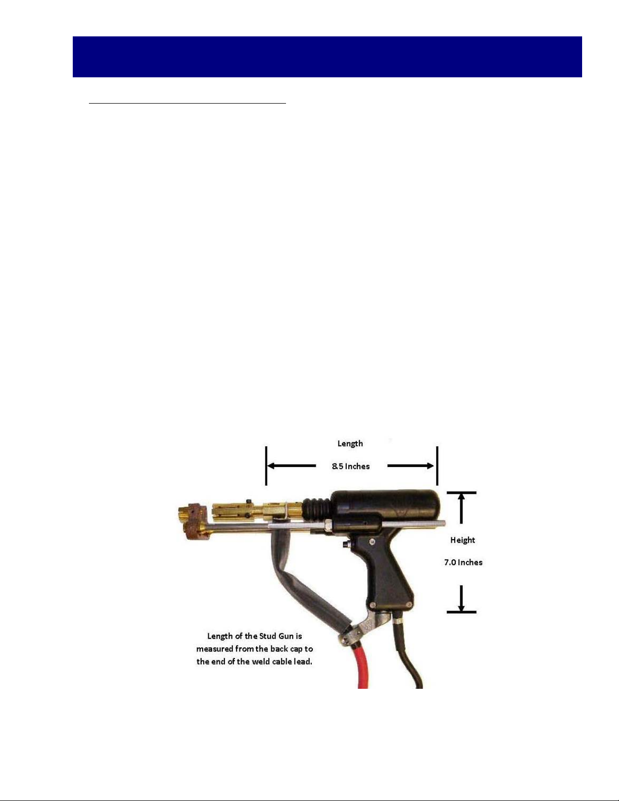
TWE17000Heavy‐DutyStudGun
16
StudGunSetup
Attachingthestudguntostartwelding
♦ Selectthegun,controlcable,andweldcablethatisrecommendedforthespecifictypeof
welderandthejob.
♦ Attachstudguntoweldandcontrolcableextension.
♦ Actuatethestudgunwithoutplacingitonthesurfacetobeweldedtoassurethatthecon‐
nectionthroughthecontrolcableiscorrecttocompletethecircuitandactuatethestudgun.
♦ Makesurewelderissetupproperlytobegintheweldingprocess.
♦ Placetheselectedstudintothechuckandattachtheferruletotheferrulegrip.
♦ Placestudontosurfacetobeweldedandpressstudgundownuntilferruleisflushwiththe
weldingsurface.
♦ Triggerthegunandholdinplaceuntilcycleiscompleted.
♦ Pullgunassemblystraightupoffoftheweldedstud.
♦ Donotdepresstriggerwhenremovinggunfromstud.
♦ Removetheferrulebybreakingitoffandinspecttheweld.
♦ Makeproperadjustmentsasneeded.
Figure1‐TWE17000Heavy‐DutyStudGun

17
SC1950Operations‐Settings
SC1950PowerSwitch/PowerOn
ThepowerswitchfortheSC1950islocatedontherightfrontof
thewelder’scontrolpanel.Turnthedialclockwisetothehorizon‐
talpositiontoturntheuniton.Verticalisthe“OFF”position.
Whenthewelderisturnedon,thedigitaldisplaywillgothrougha
self‐diagnosticcheck.Thistakesapproximately3to5seconds,
andthenthedigitaldisplaywillshowthelasttimeandcurrent
setting.
Thisdenotesthattheunitisreadytogo.
Whenconnectedtothewelder,thestudgunwillactuate3times,
indicatingthatthereisagoodconnection.
SC1950DiagnosticLights
OntheControlPanel,locatedbelowthedigitaldisplay,isarowofdiagnosticlightsforthe
welder.
OUTPUT‐Whenthestudgunistriggered,thislightcomesontoindicatethattheOCVispresent
attheoutputterminals.
TRIGGER‐Whenthestudgunistriggered,thislightcomesontoindicatethatthetriggercircuitis
functioningproperly,andthattheweldingunitisreceivingfeedbackfromthestudgun.
POWER‐Whenthislightislit,itindicatesthatthereisanerror.
TEMP‐Whenthislightislit,itindicatesthateitherthemaintransformerorweldbridgehas
reachedmaximumtemperatureandthattheunitwillnotfunctionuntilitiscooled.
REMOTE‐Thisfunctionisnotcurrentlyinuse.
DiagnosticLights
OFFPosition
ONPosition

18
SC1950Operations‐Settings
SettingWeldingControls‐TimeandCurrent
Thetimeandcurrentcontrolsarelocatedonthefrontofthewelder.Thecontrolsconsistofa
TimeButton,CurrentButton,AdjustmentDial,andaFine/CoarseSwitch.Thedigitaldisplaywill
indicatethesettingschosenduringsetup.
♦ Whensettingtimeorcurrent,depressandholddownappropriatebutton,andturnAdjust‐
mentDialclockwiseorcounter‐clockwisetothecorrectsettingonthedigitaldisplay.
♦ UsetheFine/CoarseSwitchforsettingtheappropriatetimeorcurrent‐thiswilltogglebe‐
tween10’sor100’sofampsand10th’sand100th’sofasecond.
♦ ThereisaChart(seebelow)ofapproximatesettingsforfull‐basediameterstudslocatedto
theleftoftheControls.
TimeButton
AdjustmentDial
CurrentButton
Fine/CoarseSwitch
DigitalDisplays
DIAINCHTIMESECAMPSDCDIADECDIAMM
1/40.200500.2506.35
5/16
3/8
0.300
0.350
550
600
.312
.375
7.93
9.52
7/16
1/2
0.420
0.500
700
900
.437
.500
11.11
12.70
5/8
3/4
7/8
0.670
.830
1.000
1200
1600
1800
.625
.750
.875
15.87
19.04
22.22

19
SC1950Operations‐Settings
WeldCounterandWeldCounterReset
TheSC1950isequippedwithdifferentcounterstodisplaythenumberoftimestheunithasdrawn
anarcorthestudgunhasbeenactuated.
PerpetualWeldCounter(Non‐resettable)‐Thisisarunningtotalofeverytimeanarcisdrawnon
themachine.Thisisprogrammedfromthefactoryandcannotbereset.
PerpetualGunCounter(Non‐resettable)‐Thisisarunningtotalofeverytimethestudgunis
actuatedwhetheranarcwasdrawnornot.
JobCounter(Resettable)‐Thisisarunningtotalofthenumberofweldssincethecounterwas
lastreset.Toviewthejobcounter,settheFine/CoarseSwitchtotheFineposition.Eachweldwill
berecordedontheCurrentdigitaldisplay.IftheswitchisintheCoarseposition,theweldwillstill
becounted,butwillnotbedisplayed.YoucanalsoviewtheJobCountertotalbydepressingthe
AdjustmentDialwhiletheswitchisintheCoarseposition.
ToResettheJobCounter;
1.Turnoffunit.
2.DepressandholddownTimeandCurrentbuttons.
3.Turnonmachine.
4.KeepholdingdownbuttonsuntilOUTPUTlightflashesthenreleasethebuttons.
5.JobCounterwillnowbesetat0.
6.WeldcountwillnowregisteronCurrentdigitaldisplay.
JobCounterwilldisplayhere
Pressdownandhold
20
SC1950Operations‐Welding
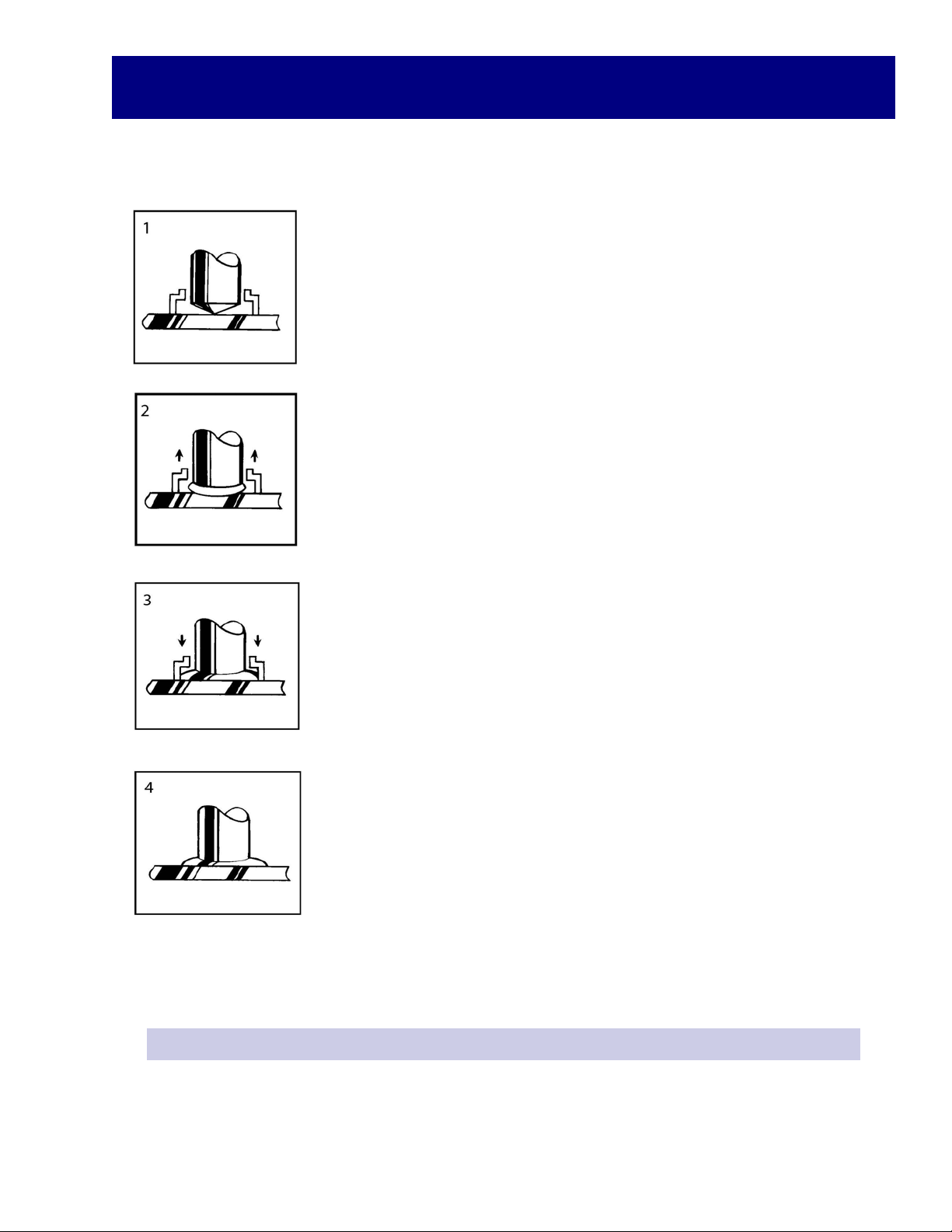
StudWelding‐StepbyStep
Theweldgunispositionedoverthebasematerialandthemaingunspring
ispartiallycompressed.Holdgunperpendiculartoworksurfaceandhold
ferrulefirmlyagainstthesurface.
Thetriggerispressedandthestudliftsoffthebase,drawinganarc.Thearc
meltstheendoftheweldstudandthebasematerialbelow.Thearcshield
(ferrule)concentratestheheatbelowtheweldstudandcontainsthemol‐
tenmetalwithintheweldzone.Donotmoveweldgunduringweld.
Themainspringplungestheweldstuddownintothemoltenpoolofmetal
inthebasematerial.Thecycleiscompletedinlessthanasecondandthe
resultingweldbonddevelopsthefullstrengthofthefastenerintheweld
zone.Allowmetaltocoolandwithdrawgunfromthestud,pullingthegun
straightupoffofthestud.
Theweldguniswithdrawnfromtheweldstudleavingandtheferrule.The
ferruleisbrokenawayanddiscarded.Visuallyinspectweld.
***Note‐whendeterminingfinishedlengthrequiredfortheparticularapplication,keepinmind
thereductioninlength(burn‐off)fromstudweldingoperations.TRU‐WELDstudlengthsareal‐
waysgivenbeforeweld.
DiameterofStudReductioninLength
1/4”thru1/2”1/8”
5/8”thru7/8”3/16”
1”andover1/4”
Table of contents
Other Truweld Welding System manuals

Truweld
Truweld TW6802 User manual

Truweld
Truweld TWP-2 User manual

Truweld
Truweld TW-i Series User manual

Truweld
Truweld TWP-1 User manual

Truweld
Truweld TWE-SC1100 User manual

Truweld
Truweld TW55000 User manual

Truweld
Truweld TWE - SC1900 User manual

Truweld
Truweld TW5600 User manual

Truweld
Truweld TW6922 User manual

Truweld
Truweld TW4300 User manual


