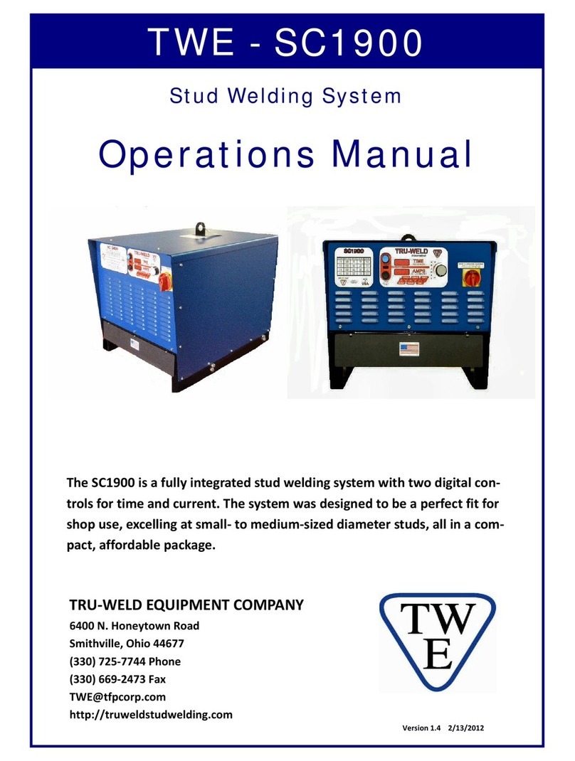
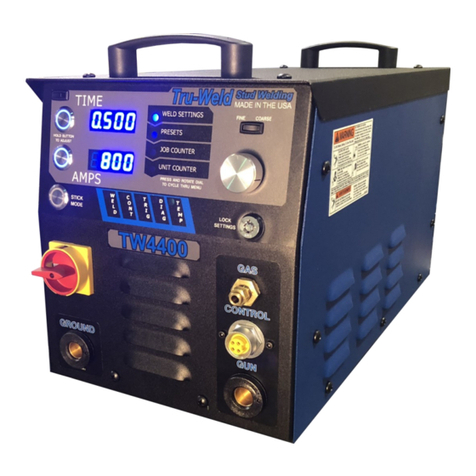
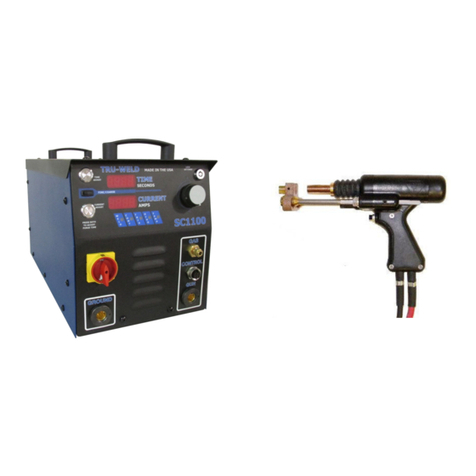
Truweld TWE-SC900 User manual

TRU‐WELDEQUIPMENTCOMPANY
6400N.HoneytownRoad
Smithville,Ohio44677
(330)725‐7744Phone
(330)669‐2473Fax
http://truweldstudwelding.com
Operations Manual
TheSC900isafullyintegratedstudweldingsystemforferrule‐
shieldedandgas‐shieldeddrawnarcstudwelding.TheSC900con‐
tainsdigitalcontrolsforweldtime,weldcurrent,andgaspurgetime.
Thesystemwasdesignedtobeaperfectfitforshopuse,weldingup
through1/2”studs.Thisisallcontainedinacompact,portablepack‐
age.
TWE - SC900
Drawn Arc Gas Short Cycle
Stud Welding System
Version2.103/24/2014

2
TRU‐WELDEQUIPMENTLIMITEDWARRANTY
AllgoodsproducedbyTruweldEquipmentshallbewarrantedagainstdefectsincludingworkmanshipandcomponents.Nootherwar‐
rantieswhetherexpressed,verbal,orimpliedwillapply.Warrantiesonlyapplytotheoriginalequipmentpurchaser.
WarrantyclaimswillbelimitedtoeitherrepairorreplacementofthedefectivematerialsbyTruweldEquipment.AttheoptionofTru‐
weldEquipmentthelocationofwherethewarrantyevaluationandrepairsaremadewillbedetermined.Allwarrantyclaimitemsre‐
turnedtoTruweldEquipmentwillbeatthecustomer’sexpense.AttheoptionofTruweldEquipmentthedefectwilleitherberepaired
orreplaced.NoticemustbeprovidedtoTruweldEquipmentofawarrantydefectwithin30daysthatthedefectorfailureisincurred.
Warrantiesarenottransferable.
Thiswarrantydoesnotapplyforequipmentwhichisusedimproperlyinanyfashionincludingbutnotexclusivetothefollowing:
Equipmentwhichhasbeenmodified
Equipmentwhichhasnotbeeninstalledproperly
Equipmentwhichhasbeenusedforpurposesotherthanwhichithadbeendesigned
Equipmentwhichhasnotbeenproperlymaintained
Equipmentwhichwascontinuedtobeusedafteradefecthadbeenfound
Equipmentwhichwasdamagedinanyway
TruweldEquipmentwillneverbeliableforconsequentialdamages,loss,orexpenseoccurringdirectlyorindirectlyfromtheuseofthe
equipmentcoveredinthiswarranty.
Allcables,cablesetsandconnectorsarenotwarranted.
Two(2)yearwarrantyperiodfromdateofpurchase
TWE250PowerSupply SC1900PowerSupply
TWE321PowerSupply SC1950PowerSupply
TWE375PowerSupply SC2400PowerSupply
SC900PowerSupply SC2402PowerSupply
SC1400PowerSupply SC2420PowerSupply
SC1450PowerSupply SC3400PowerSupply
SC1600PowerSupply SC3402PowerSupply
SC1650PowerSupply
One(1)yearwarrantyperiodfromdateofpurchase
TWESPCPowerSupplies
TWP‐2PowerSupply
NinetyDay(90)warrantyperiodfromdateofpurchase
(Excludingcablesandconnectors)
TWE70000HDArcstudgun
TWE18500MDArcstudgun
TWE19000LDArcstudgun
TWEGCDstudgun
TWEHDGHeavyDutyCDstudgun

3
CompanyandProductInformation
CompanyProfile
Tru‐WeldStudWeldinghasbeenmakingweldstudssince1959,andsince1970wehavebeenpro‐
ducingourownlineofhigh‐qualitystudweldingequipment.Tru‐WeldislocatedinMedina,Ohioand
hasproductandequipmentdistributorsacrossthenation.Tru‐WeldEquipmentCompany(TWE)of‐
fersafulllineofDrawn‐ArcandCapacitorDischarge(CD)studweldingequipment,replacementparts,
andaccessories.
OurexperiencedManagementandStaffiscommittedtoprovidetheutmostinqualityandservicein
everystepofourproduction,whileremainingcompetitiveinthemarketplace.Itisourgoaltomeet
ourcustomer'sneedsmoreeffectivelythanourcompetitorsthroughaprocessofcontinuousquality
improvement.Ourlong‐standingrelationshipwithourcustomers'andsuppliers'isourkeytocontin‐
uedsuccessandgrowth.Ifwecanbeofanyfurtherassistancetoyouandyourcompany,pleasedonot
hesitatetocontactus.
ProductInformation
TheSC900isafullyintegratedstudweldingsystemforferrule‐shieldedandgas‐shieldeddrawnarc
studwelding.TheSC900containsdigitalcontrolsforweldtime,weldcurrent,andgaspurgetime.The
systemwasdesignedtobeaperfectfitforshopuse,weldingupthrough1/2”studs.Thisisallcon‐
tainedinacompact,portablepackage.
Features:
♦ Smootharccurvetargetedforsmalltomediumsizeddiameterstuds
♦ EnhancedDutyCycleproductionrequirements
♦ Capableofupto100feetof2/0weldingcableaccommodatesalargevarietyofworkstation
layouts
♦ Steplesstimeandcurrentcontrolallowforinfinitesettingsforfine‐tuningtheweldingoutput
♦ StudJobCounterthatcanberesetforeveryjob
♦ On‐DemandFanthatcyclesonandoffwhenneeded.
CompletesystemIncludes:
800AmpPowerSupplyController,TWE19000LightDutystudgun,25feetof#1AWGcombocable,
and15feetof#1AWGgroundcablewithclamp.

4
Safetyiseveryone’sresponsibility.TRU‐WELDdesignseverymachinewithsafetyinmind,anda
safeworkenvironmentdependslargelyonyou.
Donotinstall,operate,orrepairthisequipmentwithoutcarefullyreadingthismanualandobserv‐
ingallofthesafetyprecautionsmentioned.Ifthereisaquestion,askyoursupervisor!
SafetySymbols
Everyefforthasbeenmadetoprotecttrainedoperatorsfrominjuryorunnecessaryrisk.Certain
symbolsareusedthroughoutthismanualtocallattentiontosafety‐relatedinformationandin‐
struction.Thesafetysymbolsinthismanualhavethesemeanings:
ThissymbolindicatesDangerousSituations.Whenthissymbolisusedinthismanual,
deathorseriousbodilyharmispossibleorprobableifthecorrespondingpreventative
measuresarenottaken.Operatorsmusttakecautioninthemethodandmannerof
handlingorusingthemachinewhenthissymbolisdisplayed.
SafetyPrecautions
Donotinstall,operate,orrepairtheSC900weldingequipmentwithoutreadingthismanualandall
safetyprecautionsstatedwithin!
Thismachinewasdesignedandbuiltwithoperatorsafetyinmind,butsafetybeginswithyou!
Everyefforthasbeenmadetoprotectthetrainedoperatorfrominjury.Pleasebecomefamiliar
withtheinformationinthismanualtominimizetheriskofshockorinjury.
STUDWELDINGCANBEHAZARDOUS.ALWAYSPROTECTYOURSELFANDOTHERS
FROMPOSSIBLEINJURYORDEATH.KEEPCHILDRENAWAY.
Operatorswhohaveapacemakershouldconsultwiththeirphysicianbeforeoperatingstudweld‐
ingequipment.
FUMESandOXYGENDEPLETION
♦ Onlyweldinareasorroomswhereadequateventilationofweldgasesispossibleandwhere
thereisnotfire,smokeorexplosionhazards.
♦ Whenworkinginaconfinedspacealwayshavetrainedsupportpersonnelnearby.
♦ Weldingfumesandgasescandisplaceairandlowertheoxygenlevelcausinginjuryordeath.Be
surethebreathingairissafe.
♦ Donotweldinlocationsneardegreasing,cleaning,orsprayingoperations.Theheatandraysof
thearcscanreactwithvaporstoformhighlytoxicandirritatinggases.
♦ Donotweldoncoatedmetals,suchasgalvanized,lead,orcadmiumplatedsteel.Thecoating
mustberemovedfromtheareatobewelded.Coatingsandmetalscontainingaboveelements
cangeneratetoxicfumeswhenheatedtoweldingtemperature.
StudWeldingSafetyPrecautions

5
ELECTRICSHOCK
Electricshockcaninjureorkill!
Precautionarymeasuresmustbetakentoprovidemaximumprotectionagainstelectri‐
calshock.
♦ Donottouchliveorenergizedelectricalpartsorstoremetallicobjectsnearpower.
♦ Groundtheworkormetaltobeweldedtoagoodelectrical(earth)ground.
♦ Donotleaveanenergizedmachineunattended.
♦ Neverworkinwetclothing,glovesorfootwear.
♦ Insulateyourselffromworkandgroundusingdryinsulation.Makecertaintheinsulationis
largeenoughtocoveryourfullareaofphysicalcontactwithworkandground.
♦ Inspectallsystemcomponents,protectiveequipment,cables,connectorsandgaslinesprior
tooperatingequipment.Neverusecablesthatarelongerthannecessary.
♦ Whentestingaliveunit,usetheone‐handmethod.Donotputbothhandsinsideoftheunit.
Keeponehandfree.
♦ Disconnectinputpowerconductorsfromde‐energizedsupplylinebeforemovingawelding
powersource.
♦ Alwaysbesuretheworkcablemakesagoodelectricalconnectionwiththemetalbeing
welded.Theconnectionshouldbeascloseaspossibletotheareabeingwelded.
♦ TurnOFFweldingpowersourcebeforeservicingunlesstheprocedurespecificallyrequiresan
energizedunit.
♦ Nevertouchtheenergizedstudorgunbeforedischargingthestudtoground.
♦ Neverusethepowersourcetoprovideheatforthawingfrozenpipes.
ARCRAYSandEYEPROTECTION
Arcrayscaninjureeyesandburnskin.
Arcflashesarepainful.
♦ Useashieldwiththeproperfilterandcoverplatestoprotectyoureyesfromsparksandthe
raysofthearcwhenweldingorwhileobservingopenarcwelding.
♦ Useprotectiveclothingspecificallyintendedforworkwithweldingequipment.Itshouldbe
madeofdurableflame‐resistantmaterialtoprovideampleprotectionfromthearcrays.
♦ Protectothernearbyworkerswithsuitable,non‐flammablescreening.Cautionotherworkers
nottowatchthearcnorexposethemselvestothearcraysortohotspatterormetal.
StudWeldingSafetyPrecautions

6
StudWeldingSafetyPrecautions
WELDINGSPARKS
Heatfromflamesandarcscanstartfires.Hotslagorsparkscanalsocausefiresand
explosions.
Removeallcombustiblematerialsfromtheworkareaorcoverthesematerialswithaprotectivenon‐flammabletarp.
Combustiblematerialsincludewood,fabrics,sawdust,liquidandgasfuels,solvents,paintsandcoatings,paper,etc.
Hotsparksorhotmetalcanfallthroughcracksorcrevicesinfloorsorwallopeningsandcauseahiddensmoldering
fire.Makecertainthatsuchopeningsareprotectedfromhotsparksandmetal.
ELECTRICandMAGNETICFIELDS
ElectriccurrentflowingthroughanyconductorcauseslocalizedElectro‐MagneticFields(EMF).Weldingandcutting
currentcreatesEMFaroundweldingcablesandweldingmachines.
♦ Operatorshavingpacemakersshouldconsulttheirphysicianbeforewelding.EMFmayinterferewithsometype
ofpacemakers.
♦ ExposuretoEMFmayhaveotherhealtheffects,whichareunknown.
♦ OperatorsshouldusethefollowingprocedurestominimizeexposuretoEMF:
♦ Routetheworkcablestogether.Securethemwithelectricaltapewhenpossible.
♦ Nevercoiltheworkcablearoundanypartofyourbody.
♦ Donotplaceyourbodybetweentheworkcables.Routecablesonthesamesideofyourbody.
♦ Connecttheworkcabletotheworkpieceascloseaspossibletotheareabeingwelded.
♦ Keepweldingpowersourceandcablesasfarawayfromyourbodyaspossible.
♦ Electromagneticfieldscanirrevocableerasemagneticdatacarriers(computermemory,creditcards,securityID
cardsordatastoragediskettes).
♦ Electromagneticfieldsmaymagnetizeanddamagewatchesorsimilardigitaldevices.
PROTECTYOURSELFandOTHERS!
Somewelding,cutting,andgougingprocessesarenoisyandrequireearprotection.Thearc,likethesun,
emitsultraviolet(UV)andotherradiationandmayinjureskinandeyes.Hotmetalcancauseburns.
Trainingintheproperuseofweldingprocessesandequipmentisessentialtopreventaccidents.
♦ Alwayswearsafetyglasseswithsideshieldsinanyworkarea.Inconjunctionwitheyeprotection,weldinghel‐
metsorfaceshieldsarealsorequired.
♦ Useafaceshieldfittedwiththecorrectfiltercoverplatestoprotectyoureyes,face,neck,andearsfromsparks
andraysofthearcwhenoperatingorobservingoperations.Warnbystandersnottowatchthearcandnotto
exposethemselvestotheraysoftheelectricarcorhotmetal.
♦ Wearflameprooftypegloves,heavylong‐sleeveshirt,cufflesstrousers,andaweldinghelmetorcapforhairpro‐
tection,toprotectagainstarcraysandhotsparksorhotmetal.Aflameproofapronmayalsobedesirableaspro‐
tectionagainstradiatedheatandsparks.
♦ Hotsparksormetalcanlodgeinrolledupsleeves,trousercuffs,orpockets.Sleevesandcollarsshouldbekept
buttoned,andopenpocketseliminatedfromthefrontofclothing.

7
Features
SmoothArcCurveallowsforawiderangeofwelding.
EnhancedDutyCycleforproductionrequirements.
Powerfuloutputforeventhelargestdiameterweldingprojects.
Timeandcurrentcontrolallowforinfinitesettingsforfine‐tuningtheweldingoutput.
Safetyweldinginterlockkeepssystemfromdouble‐triggering.
SC900ProductSpecifications
**Specificationsaresubjecttochangewithoutpriornotification.
WeldRange14gato1/2”Consistentweldingregardlessofstuddiameter.
DutyCycle14gathru1/4”
3/8”
1/2”
Unlimited
5‐6perminute
2‐3perminute
DimensionsHeight
Width
Length
Weight
12.6”(320mm)
11”(280mm)
22.4”(570mm)
106Lbs.(48kg)
InputVoltages230/460VAC3Phase60Hz
FusingRequirements(Slowacting)230/70Amps
460/35Amps

8
SC900SetupandInstallation
InitialSteps
Onlyqualifiedpersonnelshouldperformthisinstallation.
♦Turntheinputpoweroffatthedisconnectswitchorfuseboxbeforeworkingonthewelder.
♦Donottouchelectricallyhotparts.
ThissectionprovidesdetailedinstructionsfortheproperinstallationoftheTWESC900.Itis
recommendedthattheseinstructionsbefollowedcarefullytoallowforthebestpossibleoperat‐
ingenvironment.
HandlingandUnpackingtheWelder
Immediatelyuponreceiptofthewelder,inspecttheshipmentforanydamageandnotifythe
carrierofsuchdamagebeforeacceptingdelivery.Theninspectwelderfordamagewhichmay
haveoccurredintransit.Afterremovingthecomponentsfromtheshippingcontainer(s),check
thecontainerforanylooseparts.Removeallpackingmaterials.Visuallycheckallairpassagesof
powersourceforanypackingmaterialsthatmayobstructairflowthroughthewelder.Ifthe
equipmentisnotbeinginstalledimmediately,storeitinaclean,dry,well‐ventilatedareauntilin‐
stallation.
SelectingaLocation
Thelocationofthepowersourceshouldbecarefullyselectedtoensuresatisfactoryanddepend‐
ableservice.Choosealocationrelativelyclosetoaproperlyfusedsourceofelectricalpower.Use
careagainsttopplingoverifthemachineisplacedonatiltedsurfaceorplane.Itisimportantthat
themachinebelocatedinanopenareawhereaircancirculatefreelythroughthefrontandrear
openings.Ifspaceisatapremium,leaveatleast1foot(300mm)ofclearancebetweentherear
ofthepowersourceandwallorotherobstruction.
ElectricalInputRequirement
Theweldingpowersourceisdesignedtobeoperatedfromthree‐phase,60Hertz,ACpowersup‐
ply.Consultyourlocalelectricalutilityifyouhaveanyquestionsontheelectricalsystematthe
presentinstallationsite.TheSC900shouldbeoperatedfromaseparate,fusedorcircuit‐breaker
protectedcircuit.

9
SC900SetupandInstallation
PreparingtheUnitforPrimaryPower
Onlyqualifiedpersonnelshouldperformthisinstallation.
♦Turntheinputpoweroffatthedisconnectswitchorfuseboxbeforeworkingonthewelder.
♦Donottouchelectricallyhotparts.
RemovethetopcoveroftheSC900.Alloftheconnectionsthatwillneedtobemadeareaccessi‐
blewiththetopcoverremoved.
PrimaryPowerCable
RoutethePrimaryPowerCablethroughthePowerInletHoleinthecenterconnectorontheback‐
sideofthewelder.
Connectthepowerleads(Black,White,Red)totheL1,L2,andL3connectorsasshowninphoto
Firmlytightenscrewsthatholdthepowerleadsinplace.
Attachthegroundwire(Green)tothegroundlugofasshowninabove.
OncethePrimaryPowerCableisconnected,tightenPowerCableClamponthebackofthe
welder,holdingthepowercablefirmlyinplace.

10
SC900SetupandInstallation
Power/GroundConnections
ElectricalInputRequirement
TheSC900isequippedwithanInputVoltageJumperBlocksoyoucanoperatetheunitfromdif‐
ferentlinevoltagesdependingonyourrequirements.Simplyplugintheappropriatevoltagecon‐
nectorforeither230VAC(redwiredconnector)or460VAC(blackwiredconnector)3Phaseopera‐
tion.
GroundCableConnection
TheSC900isequippedwithonegroundcableconnectionlocatedonthefrontofthewelder
Securethegroundcabletowelderandconnectthegroundclamptotheworksurfacethe.

11
SC900SetupandInstallation
Cable/GasConnections
WeldCableConnection
TheSC900weldcableconnectionislocatedonthefrontofthewelder
ConnectstudguncableassemblydirectlytotheSC900.
Plugstudguncontrolcableplugintotheconnectoronthefrontofwelder.
Gaslineconnection
When“gasshield”weldingconnectthegaslinefromthefootpieceofthestudgunintothegas
fittingonthefrontoftheSC900byeasyquickconnectfitting.

12
StudGunSetup
StudGunSetup
Eachstudweldingapplicationrequiresthatthestudgunbesetupproperlyforthecorrectstud
andferrulearrangement.
♦ Selectthecorrectstyleandsizeofchuckforthestudtobeweldedandattachittothestud
gun.
♦ Selecttheproperlengthlegassembliesforthelengthofthestud.
♦ Selecttheproperfootpiecebestsuitedforyourapplication.
♦ Selectthegriptofittheferrulewhichisprovidedwiththestudtobewelded.
Afteralloftheproperaccessorieshavebeenmountedonthestudgunplacethestudinthechuck
andbeginthealignmentoftheaccessories.
♦ Makecertainthatasufficientamountofthestudisinsertedinthechucksothatthestudis
heldfirmly.
♦ Attachtheferruletotheferrulegrip.
♦ Plungesetting;movetheleg,footandferruleassemblysothatthestudprotrudesbeyondthe
ferrule(1/8”forstuds1/2"andunderindiameter3/16”forstudsupthrough7/8”and1/4”
for1”and1‐1/4”diameterstuds).
♦ Positionthisassemblysothatthestudmovesfreelythroughtheferrulewhenyouslidethe
shaftofthestudgunbackandforth.

13
StudGunSetup
Lift
Settheliftwhenalloftheaccessoriesandstudhavebeenproperlysetonthestudgun,priorto
welding.Plugthecontrolconnectorofthestudgundirectlyintothestudwelder(donotattachthe
weldcable).Turnonthestudwelderandactuatethetriggerofthestudgunwiththestudandfer‐
ruleinplace.Notetheretractionoftheshaftofthestudgun.ThisisdesignatedastheLift.
Theliftsettingshouldbeabout3/32”forgeneralweldingapplicationsandstudsrangingindiameter
through3/4"thisadjustmentshouldbesuitable.Forlargerdiameterstudsandselectapplications
theliftshouldbeadjustedtoapproximately1/8”.
Adjustingthelift:
♦ Removethebackcapofthestudgun.
♦ Loosenthetwosocketsetscrewsaroundtheperipheryoftheliftadjustmentscrew.
♦ Toincreaseliftrotatetheliftadjustmentscrewcounterclockwiseandtodecreaseliftrotate
clockwise.
♦ Witheachturnchecktheliftbyactuatingthestudgununtilthedesiredliftisachieved.
♦ Tightenthesocketsetscrewstoholdtheliftadjustmentscrewinplacetosecuretheselected
setting.
♦ Replacethebackcapofthestudgun.
RearCoilYoke
SetScrew
LiftAdjustingScrew
GunBody

14
StudGunSetup
FreeTravelAdjustment
Thisadjustmentcanbeusedtocontroltheforcewithwhichthestudisplungedintothemolten
weldpoolbymovingtheengagementpointofwhentheshaftofthestudgunengagesthedamp‐
ener.
Rotatingthedampenercovercounterclockwiseincreasestheamountoffreetravel.

15
StudGunSetup
Attachingthestudguntostartwelding
♦ Selectthegun,controlcable,andweldcablethatisrecommendedforthespecifictypeof
welderandthejob.
♦ Attachstudguntoweldandcontrolcableextension.
♦ Actuatethestudgunwithoutplacingitonthesurfacetobeweldedtoassurethatthecon‐
nectionthroughthecontrolcableiscorrecttocompletethecircuitandactuatethestudgun.
♦ Makesurewelderissetupproperlytobegintheweldingprocess.
♦ Placetheselectedstudintothechuckandattachtheferruletotheferrulegrip.
♦ Placestudontosurfacetobeweldedandpressstudgundownuntilferruleisflushwiththe
weldingsurface.
♦ Triggerthegunandholdinplaceuntilcycleiscompleted.
♦ Pullgunassemblystraightupoffoftheweldedstud.
♦ Donotdepresstriggerwhenremovinggunfromstud.
♦ Removetheferrulebybreakingitoffandinspecttheweld.
♦ Makeproperadjustmentsasneeded.

16
SC900PowerSwitch/PowerOn
ThepowerswitchfortheSC900islocatedontheleftfrontofthe
frontcontrolpanel.Turnthereddialclockwisetothehorizontal
position(I)indicatortoturntheunitON.Turnthedialtothever‐
ticalposition(O)indicatortoturntheunitOFF.
Whenthewelderisturnedon,thedigitaldisplaywillgothrougha
self‐diagnosticcheck.Thistakesapproximately3to5seconds,and
thenthedigitaldisplaywillshowthelasttimeandcurrentto
whichtheunitwasset.Thisdenotesthattheunitisreadytogo.
Whenconnectedtothewelder,thestudgunwillactuate3times,
indicatingthatthereisagoodconnection.
SC900DiagnosticLights
OntheControlPanel,locatedbelowthedigitaldisplay,isarowofdiagnosticlightsforthewelder.
OUTPUT‐Whenthestudgunistriggered,thislightcomesontoindicatethattheOCVispresent
attheoutputterminals.
TRIGGER‐Whenthestudgunistriggered,thislightcomesontoindicatethatthetriggercircuitis
functioningproperly,andthattheweldingunitisreceivingfeedbackfromthestudgun.
POWER‐Whenthislightislit,itindicatesthatthereisanerror.
TEMP‐Whenthislightislit,itindicatesthateitherthemaintransformerorweldbridgehas
reachedmaximumtemperatureandthattheunitwillnotfunctionuntilitiscooled.
REMOTE‐Thisfunctionisnotcurrentlyinuse.
SC900Operations‐Settings

17
SC900Operations‐Settings
SettingWeldingControls‐TimeandCurrent
Thetimeandcurrentcontrolsarelocatedonthefrontofthewelder.Thecontrolsconsistofa
TimeButton,CurrentButton,AdjustmentDial,andaFine/CoarseSwitch.Thedigitaldisplaywill
indicatethesettingschosenduringsetup.
Whensettingtimeorcurrent,depressandholddownappropriatebutton,andturnAdjustment
Dialclockwiseorcounter‐clockwisetothecorrectsettingonthedigitaldisplay.
UsetheFine/CoarseSwitchforsettingtheappropriatetimeorcurrent‐thiswilltogglebetween
10’sor100’sofampsand10th’sand100th’sofasecond.
Toadjustgaspurgetime,holdboththeTIMEandAMPSbuttonsandturnAdjustmentDial.The
settingissavedwhenthebuttonsarereleased.

18
SC900Operations‐Settings
Thereisachartofapproximatesettingsforfull‐basediameterstudslocatedonthetopcoverof
theSC900.
WeldCounterandWeldCounterReset
TheSC900isequippedwithdifferentcounterstodisplaythenumberoftimestheunithasdrawn
anarcorthestudgunhasbeenactuated.
PerpetualWeldCounter(Non‐resettable)‐Thisisarunningtotalofeverytimeanarcisdrawnon
themachine.Thisisprogrammedfromthefactoryandcannotbereset.
PerpetualGunCounter(Non‐resettable)‐Thisisarunningtotalofeverytimethestudgunis
actuatedwhetheranarcwasdrawnornot.
JobCounter(Resettable)‐Thisisarunningtotalofthenumberofweldssincethecounterwas
lastreset.Toviewthejobcounter,settheFine/CoarseSwitchtotheFineposition.Eachweldwill
berecordedontheCurrentdigitaldisplay.IftheswitchisintheCoarseposition,theweldwillstill
becounted,butwillnotbedisplayed.YoucanalsoviewtheJobCountertotalbydepressingthe
AdjustmentDialwhiletheswitchisintheCoarseposition.
ToResettheJobCounter;
1. Turnoffunit.
2. DepressandholddownTimeandCurrentbuttons.
3. Turnonmachine.
4. KeepholdingdownbuttonsuntilOUTPUTlightflashesthenreleasethebuttons.
5. JobCounterwillnowbesetat0.
6. WeldcountwillnowregisteronCurrentdigitaldisplay.
SC900approximatetimeandcurrentsettings

19
SC900Operations‐Settings
SC900SupervisorLock
Thesupervisorlockpreventsthesettingsfrombeingadjusted.Thepurposeistoallowameas‐
ureofprocesscontrol.Allsettingsandthecountermaybeviewedwhenthelockisactivated.
Toactivatethelock,turnclockwisetowardthe3o’clockposition.Todeactivatethelock,turn
counter‐clockwisetowardthe12o’clockposition.

20
SC900Operations‐Welding
StudWelding‐StepbyStep
Theweldgunispositionedoverthebasematerialandthemaingunspring
ispartiallycompressed.Holdgunperpendiculartoworksurfaceandhold
ferrulefirmlyagainstthesurface.
Thetriggerispressedandthestudliftsoffthebase,drawinganarc.Thearc
meltstheendoftheweldstudandthebasematerialbelow.Thearcshield
(ferrule)concentratestheheatbelowtheweldstudandcontainsthemol‐
tenmetalwithintheweldzone.Donotmoveweldgunduringweld.
Themainspringplungestheweldstuddownintothemoltenpoolofmetal
inthebasematerial.Thecycleiscompletedinlessthanasecondandthe
resultingweldbonddevelopsthefullstrengthofthefastenerintheweld
zone.Allowmetaltocoolandwithdrawgunfromthestud,pullingthegun
straightupoffofthestud.
Theweldguniswithdrawnfromtheweldstudleavingandtheferrule.The
ferruleisbrokenawayanddiscarded.Visuallyinspectweld.
***Note‐whendeterminingfinishedlengthrequiredfortheparticularapplication,keepinmind
thereductioninlength(burn‐off)fromstudweldingoperations.TRU‐WELDstudlengthsareal‐
waysgivenbeforeweld.
DiameterofStud ReductioninLength
1/4”thru1/2” 1/8”
Table of contents
Other Truweld Welding System manuals
Truweld
Truweld TWP-2 User manual
Truweld
Truweld TW5600 User manual
Truweld
Truweld TWP-1 User manual

Truweld
Truweld TW4300 User manual

Truweld
Truweld TW-i Series User manual
Truweld
Truweld TW55000 User manual
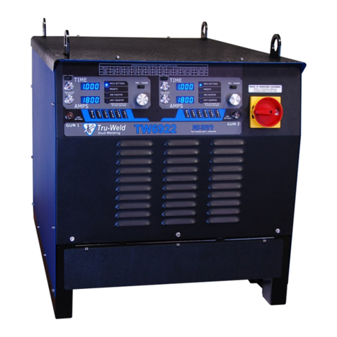
Truweld
Truweld TW6922 User manual
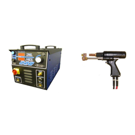
Truweld
Truweld ARWSC900 User manual
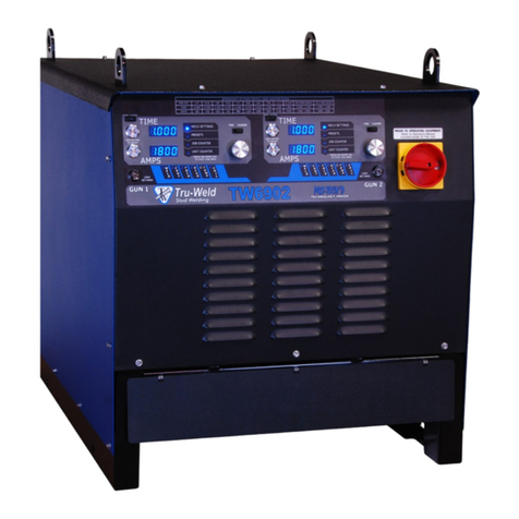
Truweld
Truweld TW6802 User manual

Truweld
Truweld TWE - 19000 User manual
Popular Welding System manuals by other brands
LOKERMANN
LOKERMANN GRAND PIPE 270 MULTI user manual
STAYER WELDING
STAYER WELDING POTENZA TIG170 HF operating instructions

ims PRO
ims PRO SPOT EXPERT 400 manual
ESAB
ESAB Aristo Mig 5000i instruction manual
Chicago Electric
Chicago Electric 93793 Set up and operating instructions
Pro-Weld
Pro-Weld CD-212P Operation manual
