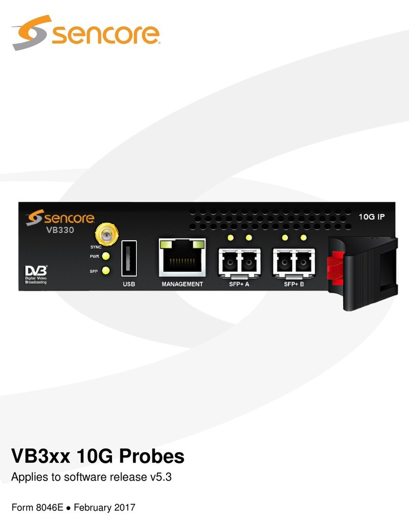
Sencore VB330 User manual

Copyright
c
2016 Sencore, Inc. All rights reserved.
3200 Sencore Drive, Sioux Falls, SD USA
www.sencore.com
This publication contains confidential, proprietary, and trade secret information. No part of this document
may be copied, photocopied, reproduced, translated, or reduced to any machine-readable or electronic
format without prior written permission from Sencore. Information in this document is subject to change
without notice and Sencore Inc. assumes no responsibility or liability for any errors or inaccuracies.
Sencore, Sencore Inc, and the Sencore logo are trademarks or registered trademarks in the United
States and other countries. All other products or services mentioned in this document are identified by
the trademarks, service marks, or product names as designated by the companies who market those
products. Inquiries should be made directly to those companies. This document may also have links to
third-party web pages that are beyond the control of Sencore. The presence of such links does not imply
that Sencore endorses or recommends the content on those pages. Sencore acknowledges the use of
third-party open source software and licenses in some Sencore products. This freely available source
code can be obtained by contacting Sencore Inc.
About Sencore
Sencore is an engineering leader in the development of high-quality signal transmission solutions for the
broadcast, cable, satellite, IPTV, and telecommunications markets. The company’s world-class portfolio
includes video delivery products, system monitoring and analysis solutions, and test and measurement
equipment, all designed to support system interoperability and backed by best-in-class customer support.
Sencore products meet the rapidly changing needs of modern media by ensuring the efficient delivery
of high-quality video from the source to the home. More information about Sencore is available at the
company’s website, www.sencore.com.
All trademarks and registered trademarks mentioned herein are the property of their respective owners.
2VB3xx 10G Probe User’s Manual version 5.2

Contents
Contents 3
1 INTRODUCTION 7
1.1 About the 10G Probe . . . . . . . . . . . . . . . . . . . . . . . . . . . . . . . . . . . . 7
1.1.1 VB330 – Overview . . . . . . . . . . . . . . . . . . . . . . . . . . . . . . . . . 7
1.1.2 10G Probe – Functionality . . . . . . . . . . . . . . . . . . . . . . . . . . . . . 8
1.2 How to use this manual . . . . . . . . . . . . . . . . . . . . . . . . . . . . . . . . . . . 9
2 PRINCIPLE OF OPERATION 10
3 SAFETY 12
4 INSTALLATION AND INITIAL SETUP 13
4.1 Quick Installation Guide . . . . . . . . . . . . . . . . . . . . . . . . . . . . . . . . . . . 13
4.2 The Enhanced Chassis (VB300) . . . . . . . . . . . . . . . . . . . . . . . . . . . . . . 13
4.2.1 Dual Power Supply . . . . . . . . . . . . . . . . . . . . . . . . . . . . . . . . . 14
4.2.2 Cooling System . . . . . . . . . . . . . . . . . . . . . . . . . . . . . . . . . . . 14
4.3 The Enhanced Chassis –48V DC version (VB300-DC) . . . . . . . . . . . . . . . . . . 14
4.3.1 Dual Power Supply . . . . . . . . . . . . . . . . . . . . . . . . . . . . . . . . . 15
4.3.2 Cooling System . . . . . . . . . . . . . . . . . . . . . . . . . . . . . . . . . . . 15
4.3.3 VB300-DC Power Supply . . . . . . . . . . . . . . . . . . . . . . . . . . . . . . 16
4.4 Serial Number Location . . . . . . . . . . . . . . . . . . . . . . . . . . . . . . . . . . . 16
4.5 The Hardware Modules and Connectors . . . . . . . . . . . . . . . . . . . . . . . . . . 17
4.5.1 The 10G Probe Module . . . . . . . . . . . . . . . . . . . . . . . . . . . . . . . 17
4.6 Installing the Unit in a Rack . . . . . . . . . . . . . . . . . . . . . . . . . . . . . . . . . 18
4.6.1 Default Installation — Connectors at the Front of Rack . . . . . . . . . . . . . . 18
4.6.2 Optional Installation — Connectors at the Rear of Rack . . . . . . . . . . . . . 18
4.6.3 Optional Installation — Mid-Mounting . . . . . . . . . . . . . . . . . . . . . . . 18
4.7 Powering up the Unit . . . . . . . . . . . . . . . . . . . . . . . . . . . . . . . . . . . . . 19
4.8 Initial Configuration . . . . . . . . . . . . . . . . . . . . . . . . . . . . . . . . . . . . . . 19
4.8.1 Initial Configuration Using the Pre-Set IP-Address . . . . . . . . . . . . . . . . 19
4.8.2 Initial Configuration Via Serial Console Emulated Over USB . . . . . . . . . . . 20
4.8.3 Verifying Correct Initial Setup of the 10G Probe . . . . . . . . . . . . . . . . . . 22
4.8.4 Initial Setup Troubleshooting . . . . . . . . . . . . . . . . . . . . . . . . . . . . 23
VB3xx 10G Probe User’s Manual version 5.2 3

5 QUICK SETUP GUIDE 24
5.1 Basic Setup . . . . . . . . . . . . . . . . . . . . . . . . . . . . . . . . . . . . . . . . . . 24
5.2 Input Signal Definitions . . . . . . . . . . . . . . . . . . . . . . . . . . . . . . . . . . . 24
5.2.1 Multicasts . . . . . . . . . . . . . . . . . . . . . . . . . . . . . . . . . . . . . . 24
5.2.2 OTT Input (OTT Engine Option Only) . . . . . . . . . . . . . . . . . . . . . . . 25
5.3 Monitoring . . . . . . . . . . . . . . . . . . . . . . . . . . . . . . . . . . . . . . . . . . 25
5.4 Adjusting Alarm Thresholds . . . . . . . . . . . . . . . . . . . . . . . . . . . . . . . . . 25
6 THE 10G PROBE GRAPHICAL USER INTERFACE 27
6.1 Main ............................................. 28
6.1.1 Main — Summary . . . . . . . . . . . . . . . . . . . . . . . . . . . . . . . . . . 28
6.1.2 Main — CPU usage . . . . . . . . . . . . . . . . . . . . . . . . . . . . . . . . . 32
6.1.3 Main — Thumb overview . . . . . . . . . . . . . . . . . . . . . . . . . . . . . . 32
6.1.4 Main — Eii graphing . . . . . . . . . . . . . . . . . . . . . . . . . . . . . . . . . 34
6.2 Alarms ............................................ 35
6.2.1 Alarms — All Alarms . . . . . . . . . . . . . . . . . . . . . . . . . . . . . . . . 36
6.2.2 Alarms — Flash Alarms (FLASH option) . . . . . . . . . . . . . . . . . . . . . . 37
6.2.3 Alarms — Alarm setup . . . . . . . . . . . . . . . . . . . . . . . . . . . . . . . 37
6.3 OTT (Option) . . . . . . . . . . . . . . . . . . . . . . . . . . . . . . . . . . . . . . . . . 43
6.3.1 OTT — Active testing . . . . . . . . . . . . . . . . . . . . . . . . . . . . . . . . 43
6.3.2 OTT — Details . . . . . . . . . . . . . . . . . . . . . . . . . . . . . . . . . . . 44
6.3.2.1 OTT — Details — Profiles . . . . . . . . . . . . . . . . . . . . . . . . 45
6.3.2.2 OTT — Details — Manifest . . . . . . . . . . . . . . . . . . . . . . . 47
6.3.2.3 OTT — Details — Alarms . . . . . . . . . . . . . . . . . . . . . . . . 49
6.3.2.4 OTT — Details — Thumbnails . . . . . . . . . . . . . . . . . . . . . 50
6.3.2.5 OTT — Details — Alignment . . . . . . . . . . . . . . . . . . . . . . 51
6.3.3 OTT — Channels . . . . . . . . . . . . . . . . . . . . . . . . . . . . . . . . . . 52
6.3.4 OTT — Settings . . . . . . . . . . . . . . . . . . . . . . . . . . . . . . . . . . . 54
6.3.5 OTT — Thresholds . . . . . . . . . . . . . . . . . . . . . . . . . . . . . . . . . 55
6.4 Multicasts . . . . . . . . . . . . . . . . . . . . . . . . . . . . . . . . . . . . . . . . . . . 57
6.4.1 Multicasts — Parameters . . . . . . . . . . . . . . . . . . . . . . . . . . . . . . 57
6.4.2 Multicasts — Parameters — Fields . . . . . . . . . . . . . . . . . . . . . . . . . 67
6.4.3 Multicasts — Summary . . . . . . . . . . . . . . . . . . . . . . . . . . . . . . . 67
6.4.4 Multicasts — History . . . . . . . . . . . . . . . . . . . . . . . . . . . . . . . . 69
6.4.5 Multicasts — Join . . . . . . . . . . . . . . . . . . . . . . . . . . . . . . . . . . 70
6.4.6 Multicasts — Streams . . . . . . . . . . . . . . . . . . . . . . . . . . . . . . . . 71
6.4.7 Multicasts — Ethernet thresh. . . . . . . . . . . . . . . . . . . . . . . . . . . . 75
6.5 MW (Media Window) . . . . . . . . . . . . . . . . . . . . . . . . . . . . . . . . . . . . . 77
6.6 RDP (Return Data Path) . . . . . . . . . . . . . . . . . . . . . . . . . . . . . . . . . . . 80
6.6.1 RDP — Control . . . . . . . . . . . . . . . . . . . . . . . . . . . . . . . . . . . 81
6.6.2 RDP — Setup . . . . . . . . . . . . . . . . . . . . . . . . . . . . . . . . . . . . 82
6.7 Traffic............................................. 84
6.7.1 Traffic — Protocols (requires AET-OPT) . . . . . . . . . . . . . . . . . . . . . . 84
6.7.2 Traffic — Detect . . . . . . . . . . . . . . . . . . . . . . . . . . . . . . . . . . . 85
6.7.3 Traffic — Filter statistics (AET Option) . . . . . . . . . . . . . . . . . . . . . . . 87
4VB3xx 10G Probe User’s Manual version 5.2

6.7.4 Traffic — Filter setup (AET Option) . . . . . . . . . . . . . . . . . . . . . . . . . 90
6.7.5 Traffic — Microbitrate (AET Option) . . . . . . . . . . . . . . . . . . . . . . . . 92
6.8 Ethernet ........................................... 94
6.8.1 Ethernet — IGMP . . . . . . . . . . . . . . . . . . . . . . . . . . . . . . . . . . 94
6.8.2 Ethernet — FSM . . . . . . . . . . . . . . . . . . . . . . . . . . . . . . . . . . 94
6.8.2.1 Ethernet — FSM — Monitor . . . . . . . . . . . . . . . . . . . . . . . 95
6.8.2.2 Ethernet — FSM — Setup . . . . . . . . . . . . . . . . . . . . . . . 96
6.8.2.3 Ethernet — FSM — Syslog . . . . . . . . . . . . . . . . . . . . . . . 98
6.8.3 Ethernet — PCAP . . . . . . . . . . . . . . . . . . . . . . . . . . . . . . . . . . 99
6.9 ETR 290 (Option) . . . . . . . . . . . . . . . . . . . . . . . . . . . . . . . . . . . . . . 100
6.9.1 ETR 290 — ETR Overview . . . . . . . . . . . . . . . . . . . . . . . . . . . . . 101
6.9.2 ETR 290 — ETR Details . . . . . . . . . . . . . . . . . . . . . . . . . . . . . . 102
6.9.3 ETR 290 — PIDs . . . . . . . . . . . . . . . . . . . . . . . . . . . . . . . . . . 104
6.9.4 ETR 290 — Services . . . . . . . . . . . . . . . . . . . . . . . . . . . . . . . . 106
6.9.5 ETR 290 — Bitrates . . . . . . . . . . . . . . . . . . . . . . . . . . . . . . . . . 110
6.9.6 ETR 290 — Tables . . . . . . . . . . . . . . . . . . . . . . . . . . . . . . . . . 110
6.9.7 ETR 290 — PCR . . . . . . . . . . . . . . . . . . . . . . . . . . . . . . . . . . 113
6.9.8 ETR 290 — T2MI (Option) . . . . . . . . . . . . . . . . . . . . . . . . . . . . . 115
6.9.9 ETR 290 — SCTE 35 (Option) . . . . . . . . . . . . . . . . . . . . . . . . . . . 119
6.9.10 ETR 290 — Status . . . . . . . . . . . . . . . . . . . . . . . . . . . . . . . . . 121
6.9.11 ETR 290 — Compare . . . . . . . . . . . . . . . . . . . . . . . . . . . . . . . . 122
6.9.12 ETR 290 — ETR thr. . . . . . . . . . . . . . . . . . . . . . . . . . . . . . . . . 127
6.9.13 ETR 290 — PID thresh. . . . . . . . . . . . . . . . . . . . . . . . . . . . . . . . 135
6.9.14 ETR 290 — Service thresh. . . . . . . . . . . . . . . . . . . . . . . . . . . . . 138
6.9.15 Golden TS reference . . . . . . . . . . . . . . . . . . . . . . . . . . . . . . . . 140
6.10 Setup............................................. 146
6.10.1 Setup — Params . . . . . . . . . . . . . . . . . . . . . . . . . . . . . . . . . . 146
6.10.2 Setup — Pages . . . . . . . . . . . . . . . . . . . . . . . . . . . . . . . . . . . 148
6.10.3 Setup — Colors (requires EXTRACT-OPT) . . . . . . . . . . . . . . . . . . . . 149
6.10.4 Setup — Time . . . . . . . . . . . . . . . . . . . . . . . . . . . . . . . . . . . . 150
6.10.5 Setup — Ethernet . . . . . . . . . . . . . . . . . . . . . . . . . . . . . . . . . . 150
6.10.5.1 Setup — Ethernet — IPv6 Settings . . . . . . . . . . . . . . . . . . . 152
6.10.5.2 Example 1 – Separate Management IPv4 . . . . . . . . . . . . . . . 153
6.10.5.3 Example 2 – In-Line Management IPv4 . . . . . . . . . . . . . . . . 154
6.10.5.4 Example 3 – Mixed Mode IPv4 . . . . . . . . . . . . . . . . . . . . . 154
6.10.6 Setup — VLANs . . . . . . . . . . . . . . . . . . . . . . . . . . . . . . . . . . . 155
6.10.7 Setup — VBC . . . . . . . . . . . . . . . . . . . . . . . . . . . . . . . . . . . . 156
6.10.8 Setup — Login . . . . . . . . . . . . . . . . . . . . . . . . . . . . . . . . . . . 156
6.10.9 Setup — ETR . . . . . . . . . . . . . . . . . . . . . . . . . . . . . . . . . . . . 158
6.10.9.1 Parsing rules for private descriptors . . . . . . . . . . . . . . . . . . 158
6.10.9.2 ETR 290 tuning control . . . . . . . . . . . . . . . . . . . . . . . . . 159
6.10.9.3 ETR details . . . . . . . . . . . . . . . . . . . . . . . . . . . . . . . 159
6.10.9.4 EIT table IDs . . . . . . . . . . . . . . . . . . . . . . . . . . . . . . . 159
6.10.9.5 Inactive inputs . . . . . . . . . . . . . . . . . . . . . . . . . . . . . . 160
6.10.10 Setup — VBC thresh. . . . . . . . . . . . . . . . . . . . . . . . . . . . . . . . . 160
VB3xx 10G Probe User’s Manual version 5.2 5

6.10.11 Setup — Scheduling . . . . . . . . . . . . . . . . . . . . . . . . . . . . . . . . 162
6.10.12 Setup — Routing . . . . . . . . . . . . . . . . . . . . . . . . . . . . . . . . . . 163
6.10.13 Setup — Security . . . . . . . . . . . . . . . . . . . . . . . . . . . . . . . . . . 164
6.11 Data.............................................. 165
6.11.1 Data — Configuration . . . . . . . . . . . . . . . . . . . . . . . . . . . . . . . . 165
6.11.2 Data — Software . . . . . . . . . . . . . . . . . . . . . . . . . . . . . . . . . . 166
6.11.3 Data — Table Descriptors . . . . . . . . . . . . . . . . . . . . . . . . . . . . . . 167
6.11.4 Data — Eii . . . . . . . . . . . . . . . . . . . . . . . . . . . . . . . . . . . . . . 168
6.11.5 Data — Storage (FLASH option) . . . . . . . . . . . . . . . . . . . . . . . . . . 169
6.12 About............................................. 170
6.12.1 About — Release info . . . . . . . . . . . . . . . . . . . . . . . . . . . . . . . . 170
6.12.2 About — License . . . . . . . . . . . . . . . . . . . . . . . . . . . . . . . . . . 171
6.12.3 About — Technologies . . . . . . . . . . . . . . . . . . . . . . . . . . . . . . . 171
6.12.4 About — Credits . . . . . . . . . . . . . . . . . . . . . . . . . . . . . . . . . . . 172
A Appendix: VB330 Versus VBC Alarms 173
B Appendix: Monitoring Practices 175
B.1 RTP Monitoring . . . . . . . . . . . . . . . . . . . . . . . . . . . . . . . . . . . . . . . . 175
B.2 Default Monitoring . . . . . . . . . . . . . . . . . . . . . . . . . . . . . . . . . . . . . . 175
B.3 Strategy for MediaWindow Analysis . . . . . . . . . . . . . . . . . . . . . . . . . . . . . 177
B.3.1 IAT Before and After Router . . . . . . . . . . . . . . . . . . . . . . . . . . . . 178
B.3.2 Identifying UDP Packet Loss . . . . . . . . . . . . . . . . . . . . . . . . . . . . 179
B.4 Thresholds . . . . . . . . . . . . . . . . . . . . . . . . . . . . . . . . . . . . . . . . . . 180
C Appendix: OTT Profile Health 181
C.1 OTT Profile Health Bar . . . . . . . . . . . . . . . . . . . . . . . . . . . . . . . . . . . . 181
C.2 OTT Profile Health Timeline . . . . . . . . . . . . . . . . . . . . . . . . . . . . . . . . . 182
D Appendix: Software Upload 183
D.1 Step 1: Obtain the software image . . . . . . . . . . . . . . . . . . . . . . . . . . . . . 183
D.2 Step 2: Export and save the probe configuration . . . . . . . . . . . . . . . . . . . . . . 183
D.3 Step 3: Delete an existing probe stream recording . . . . . . . . . . . . . . . . . . . . . 183
D.4 Step 4: Transfer the image to the probe and save to flash . . . . . . . . . . . . . . . . . 184
D.5 Step 5: Wait while the software is being saved . . . . . . . . . . . . . . . . . . . . . . . 186
D.6 Step 6: Verify the new image . . . . . . . . . . . . . . . . . . . . . . . . . . . . . . . . 186
D.7 Software upload troubleshooting . . . . . . . . . . . . . . . . . . . . . . . . . . . . . . 186
Build ID 9345e02e7e51ebaf5e2a0f6e8e545ba6d22f1e1f
Last modified 2016-02-03
6VB3xx 10G Probe User’s Manual version 5.2

1 INTRODUCTION
1.1 About the 10G Probe
1.1.1 VB330 – Overview
The VB330 10G Probe was made specifically for IPTV backbone network monitoring. Equipped with
two 10G SFP+ optical Ethernet inputs the probe provides detailed IP-packet monitoring of a very high
number of Ethernet streams, suitable for core networks carrying extreme amounts of media signals.
The OTT software option is available on the VB330 and enables monitoring of up to 500 adaptive bitrate
channels in steps of 5 or 50 (Bulk OTT option) OTT engines depending on licensing.
A built-in web server in the VB330 allows remote signal monitoring using a standard web-browser.
Management may take place either via a separate Ethernet network, or using the regular video/data
network – both IPv4 and IPv6 are supported.
The VB330 10G Probe can also be managed via the VideoBRIDGE Controller. The VideoBRIDGE
Controller will add management features like alarm aggregation and report functionality.
VB3xx 10G Probe User’s Manual version 5.2 7

The VB330 10G Probe is a module housed in a 1 RU chassis. Several VB330 modules may be installed
in one chassis, extending the monitoring capacity.
1.1.2 10G Probe – Functionality
An IP-based network is fully transparent with respect to signal contents quality, provided that the IP-
packets arrive, and provided that they arrive in time. The 10G Probe therefore uses the patented
MediaWindow to allow monitoring at-a-glance of packet loss and errors in inter-packet arrival time. This
way the operator can conveniently ensure correct signal quality at IP-level.
The advanced Ethernet protocol analysis tool automatically detects all protocols carried over Ethernet
past the port the 10G Probe is connected to, and it displays statistics like percentage utilization of the
interface and percentage of the different transported protocols. This gives the 10G Probe a real-time
sniffer capability.
The 10G Probe allows the user to define a Return Data Path (RDP), using the regular video/data network
or the management network to return a stream. A faulty signal can then be further analyzed at the studio
premises, when necessary.
The recording functionality allows the user to record a stream, either triggered manually by the user or
triggered by a user defined alarm.
Full Service Monitoring (FSM) checks that vital system components like CA-servers are active.
Optional Ethernet TR 290 monitoring allows the operator to check parameters like transport stream sync
and PSI/SI standards conformity. This option also performs further PSI/SI analysis, making it possible to
view PSI/SI contents. PID and service bitrates are also continuously measured.
8VB3xx 10G Probe User’s Manual version 5.2

Optional OTT monitoring allows the operator to set up active testing of Over-the-top type signals as found
in adaptive bitrate streaming architectures. Formats supported include Apple (tm) HLS, Microsoft (tm)
Smoothstream, RTMP, MPEG DASH and Adobe (tm) HDS.
The 10G Probe can also be licensed with an SCTE 35 option that allows monitoring and logging of splice
time codes embedded in the transport streams.
1.2 How to use this manual
This User’s Manual is valid for software version 5.2 of the VB330 10G Probe.
Throughout this manual the term stream is often used rather than unicast or multicast. One stream may
consist of one or more services, and refers to one IP uni- or multicast.
Chapter 3 SAFETY lists safety precautions, and this chapter should be read prior to equipment installation.
Chapter 4 INSTALLATION AND INITIAL SETUP explains how to install the equipment in a rack, and
also how to perform the necessary initial configuration of the 10G Probe management IP-address. A
step-by-step quick installation guide is found in section 4.1.
Chapter 5 QUICK SETUP GUIDE contains a quick setup guide; a step-by-step description of how to
setup a 10G Probe once the initial setup has been performed.
Chapter 6 THE 10G PROBE GRAPHICAL USER INTERFACE describes the graphical user interface
(GUI) as seen when pointing a web browser to the 10G Probe’s IP-address.
A Appendix: VB330 Versus VBC Alarms describes the alarm handling in the 10G Probe versus the
VideoBRIDGE Controller.
B Appendix: Monitoring Practices explains some useful Ethernet monitoring practices.
C Appendix: OTT Profile Health explains the OTT profile health bar and timeline.
D Appendix: Software Upload explains how to upgrade the software on the 10G Probe.
Note that current version of the User’s Manual can be obtained from Sencore ProCare support by
emailing [email protected].
VB3xx 10G Probe User’s Manual version 5.2 9

2 PRINCIPLE OF OPERATION
The VB330 module is equipped with two SFP+ optical ports and one Ethernet port. Management of the
VB330 is conducted via the Ethernet management port or alternatively in-band via the optical video/data
ports.
Figure 2.1: The VB330 10G Probe Module – Principle of Operation
A simplified diagram of the alarm handling mechanisms of the 10G Probe is shown in figure 2. The
input signals are continuously analyzed, and measured data are checked against user defined threshold
values. If the data do not comply with the threshold values alarms will be generated. The overall alarm
settings further make it possible to enable and disable alarms, thus defining which alarms should be
reported in the 10G Probe alarm list and sent as SNMP traps to an external management system.
10 VB3xx 10G Probe User’s Manual version 5.2

Figure 2.2: Simplified Diagram of the Alarm Handling in the 10G Probe
VB3xx 10G Probe User’s Manual version 5.2 11

3 SAFETY
Read the installation instructions before connecting the chassis unit to the power source. Do
not install the chassis unit with power on.
The chassis is intended for installation in restricted access areas. A restricted access area can
be accessed only through the use of a special tool, lock and key, or other means of security.
Blank face plates and cover panels serve three important functions: they prevent exposure to
hazardous voltages and currents inside the chassis, they provide electromagnetic interference
shielding and they direct the flow of cooling air through the chassis. Do not operate the chassis
unit unless all modules, face plates, front covers and rear covers are in place.
Only trained and qualified personnel should be allowed to install, replace or service this equip-
ment.
This equipment must be installed and maintained by service personnel as defined by AS/NZS
3260. Incorrectly connecting this equipment to a general-purpose outlet could be hazardous.
The 10G Probe is shipped with an SX SFP+ module that is equipped with a Class 1 laser. Do not
stare into open optical ports. Note that if the SFP+ module is replaced special precautions may
have to be taken – refer to the manufacturers instructions. SFP+ modules are static sensitive
devices, and ESD-preventive measures should be taken when handling them, to avoid damage.
Ultimate disposal of this product should be handled according to all national laws and regula-
tions.
To prevent the system from overheating, do not operate it in an area that exceeds the maximum
ambient temperature of 45 degrees Celsius.
Do not work on the system or connect or disconnect cables during periods of lightning activity.
The chassis requires short-circuit (overcurrent) protection. Ensure that the protective device is
rated not greater than 120 VAC, 15 A; 240 VAC, 16 A; 60 VDC, 20 A.
12 VB3xx 10G Probe User’s Manual version 5.2

4 INSTALLATION AND INITIAL SETUP
4.1 Quick Installation Guide
1. Read the safety instructions, refer to chapter 3
2. Install the unit in a 19 inch rack for rack mount probes, refer to section 4.6
3. Connect the signal cables, refer to section 5.1
4. Power up the unit, refer to section 4.7
5. Perform initial set-up of IP-addresses, refer to section 4.8.1
6. Verify that the GUI launches correctly, refer to section 4.8.3
4.2 The Enhanced Chassis (VB300)
The 1RU Enhanced Chassis can house a maximum of
2
modules, and it is equipped with two 100–240V
AC 75W power supplies. The unit is forced air ventilated, the air flow going from front to back. The
maximum power consumption of the chassis with optional modules is 75W. By default all connectors are
located at the front of the unit. The power plugs are located at the rear of the unit. The rack ears of the
chassis may be moved to provide for mid or rear mounting of the unit. The rack ears are designed to
support the weight of the unit.
Figure 4.1: The Enhanced Chassis with probe boards installed
VB3xx 10G Probe User’s Manual version 5.2 13

Figure 4.2: Red LED indicating failure for one of the power supplies
4.2.1 Dual Power Supply
The Enhanced Chassis (VB300) is delivered with two 100–240V AC / 75W power supplies, providing
power redundancy. In normal operation load is shared between the two power supplies. If mains fall-out
occurs for one of the power sources or one of the power supplies fails, the power supply still in operation
will take the full load, seamlessly. This means that monitoring operation will not be affected if one of the
power sources fails. Power supply failure will be indicated by a red LED located rightmost on the front of
the chassis.
4.2.2 Cooling System
The chassis is equipped with six long-life fans that suck in air from front of the chassis. The air exits at the
back of the unit. The fans are temperature controlled, allowing them to run at an optimum speed. Venting
holes at the sides of the chassis provide an optional air intake, ensuring good aerodynamical properties
of the cooling air flow. It is recommended, but not essential, that these venting holes are not covered.
4.3 The Enhanced Chassis –48V DC version (VB300-DC)
The 1RU Enhanced Chassis can house a maximum of
2
modules, and it is equipped with two –48V DC
75W power supplies. The unit is forced air ventilated, the air flow going from front to back. The maximum
power consumption of the chassis with optional modules is 75W. By default all connectors are located at
the front of the unit. The power plugs are located at the rear of the unit. The rack ears of the chassis
may be moved to provide for mid or rear mounting of the unit. The rack ears are designed to support the
weight of the unit.
14 VB3xx 10G Probe User’s Manual version 5.2

4.3.1 Dual Power Supply
Figure 4.3: VB300-DC rear: two –48V DC connectors located on the the right
The Enhanced Chassis (VB300) is delivered with two –48V DC / 75W power supplies, providing power
redundancy. Each VB300 unit consists of a 1RU chassis with
2
option slots. In normal operation load is
shared between the two power supplies. If mains fall-out occurs for one of the power sources or one of
the power supplies fails, the power supply still in operation will take the full load, seamlessly. This means
that monitoring operation will not be affected if one of the power sources fails. Power supply failure will
be indicated by a red LED located rightmost on the front of the chassis.
Figure 4.4: Red LED indicating failure for one of the power supplies
4.3.2 Cooling System
The chassis is equipped with six long-life fans that suck in air from front of the chassis. The air exits at the
back of the unit. The fans are temperature controlled, allowing them to run at an optimum speed. Venting
holes at the sides of the chassis provide an optional air intake, ensuring good aerodynamical properties
of the cooling air flow. It is recommended, but not essential, that these venting holes are not covered.
VB3xx 10G Probe User’s Manual version 5.2 15

4.3.3 VB300-DC Power Supply
The VB300-DC unit is equipped with two –48V DC / 50W power inlet connectors. The power plug is a
male 3-PIN D-sub(15) connector. Matching female plugs are supplied with the VB300-DC unit. This plug
should be soldered to the power cable in accordance with the drawing in figure 4.6.
Figure 4.5: The VB200-DC Power connector on the chassis
Figure 4.6: Soldering the Female 3-PIN D-sub(15) Connector to the Power Cable
4.4 Serial Number Location
The serial number of the Enhanced Chassis is located at the rear of the unit. The serial numbers of the
individual optional modules are located on the components side of the modules. All serial numbers can
also be found on the shipping box.
All modules except the demodulator interface modules have a serial number that is available via the web
GUI under About License.
16 VB3xx 10G Probe User’s Manual version 5.2

4.5 The Hardware Modules and Connectors
4.5.1 The 10G Probe Module
The VB330 module is equipped with the following connectors:
SYNC: 1PPS input (for future use)
USB: USB serial port emulator for initial set-up of the probe – Type A
MANAGEMENT:
For optionally running management of the probe on a separate network –
RJ-45. This interface supports T10/100/1000.
SFP+ A: SFP+ optical interface (optional interface not enabled by default)
SFP+ B: SFP+ optical interface – main data input.
The VB330 module‘s SFP+ B port is shipped with an SR (short range) SFP+
module. This should be replaced if the system requires a different SFP+
module, e.g. for use with single mode fibre. Note that using other SFP+
modules than the type shipped may imply that special safety precautions
must be taken, like using protective glasses. Refer to the manufacturer for
instructions.
A number of LEDs serve the following purposes:
PWR: Green power LED
STAT: Green status LED for future use
MANAGEMENT:
The green LEDs indicate link and activity. A blinking LED indicates activity,
whereas a steadily lit LED indicates link without activity (traffic). If the left LED
is active the speed is 10/100Mbps, the right LED indicates 1000Mbps.
LINK: Green LED indicating SFP link status
ACT: Green LED indicating SFP activity (traffic)
VB3xx 10G Probe User’s Manual version 5.2 17

4.6 Installing the Unit in a Rack
The following equipment is needed for hardware installation of the unit:
•4 rack screws
•A screw driver for the rack screws
•For rear mounting: a size 2 Phillips screwdriver for rack ear screws
4.6.1 Default Installation — Connectors at the Front of Rack
By default the Enhanced chassis is shipped with rack ears for front mounting of the unit. The rack ears
are designed to support the weight of the unit, so no additional support, like a rack shelf, is needed.
When deciding where to locate the unit, make sure there is sufficient space surrounding the unit to allow
efficient cooling.
Use four rack screws to install the unit in the rack.
4.6.2 Optional Installation — Connectors at the Rear of Rack
For rear mounting of the chassis, the rack ears should be moved prior to rack installation. Unscrew the
six size 2 Phillips screws holding the rack ears, and move the six screws covering the rear mounting
holes to the front mounting holes. Remount the rack ears at the rear end of the unit.
Install the unit as described in section 4.2.2.
4.6.3 Optional Installation — Mid-Mounting
The Enhanced Chassis allows rack ears to be mid-mounted. This can be convenient if the chassis is
installed in a telco environment. Unscrew the six size 2 Phillips screws holding the rack ears, and move
the six screws covering the mid mounting holes to the front mounting holes. Remount the rack ears at
the middle of the unit.
Figure 4.7: Rack Ears Mounting – Side View of Enhanced Chassis Showing Screw Holes
18 VB3xx 10G Probe User’s Manual version 5.2

4.7 Powering up the Unit
Once the chassis is securely mounted and signal cables are connected, it can be powered up by
connecting the power cable to a mains source. When the power cable is connected the power LEDs of
the individual optional modules should light up and the chassis fans should operate.
Note that it will take some time from power-up until the modules can be accessed via the management
interface – typically the start-up may take up to two minutes.
4.8 Initial Configuration
There are two alternative ways of performing an initial configuration of the probe module:
1. By using the preconfigured IP-address of the probe management portable
2. Via serial console emulated over USB
For most users the first method will be the easiest.
Note that if there are two 10G Probe modules in the chassis, each module should be configured
individually, one by one.
4.8.1 Initial Configuration Using the Pre-Set IP-Address
The 10G Probe modules are shipped with the following factory settings:
Management (eth1) IP address: 10.0.20.101
Management (eth1) subnet mask: 255.255.0.0
In order to connect to the eth1 management port, the PC used for setup should have corresponding
network settings.
For Windows XP the network parameters are set in the
Control Panel — Network Connections —
Local Connections — Properties — Internet Protocol (TCP/IP)
view. Select the user defined address,
and set the PC’s IP-address to 10.0.20.100 and the netmask to 255.255.0.0.
When the IP-address of the PC has been set to match the VB330 factory setting, the permanent network
settings can be configured through the VB330 web browser interface.
VB3xx 10G Probe User’s Manual version 5.2 19

4.8.2 Initial Configuration Via Serial Console Emulated Over USB
If the 10G Probe for some reason cannot be reached through Ethernet communication, the initial set-up
may be performed via serial console emulated over USB. This is done by:
1. Installing a driver for the USB communication, if not already supported by the operating system
2. Setting the management IP-address
Installing a Driver for the USB Communication
The probe module uses a serial port emulator chip called FTDI FT232. Newer operating systems will
support the driver for this chip, but users of older operating systems may have to download and install
it. The driver may be downloaded directly from the chip manufacturer at
http://www.ftdichip.com/
.
Select first Drivers, then VCP followed by the operating system (VCP is short for Virtual COM Port).
For Windows XP installation of the driver do the following:
1. Temporarily disconnect the internet connection of the PC.
2. Connect the supplied USB cable between the probe and a USB port on the PC.
3. When asked to connect to Windows Update, select ‘No not this time’.
4. Select ‘Install from a list or specific location (Advanced)’.
5. Select ‘Search for the best driver in these locations’ and enter the file path.
6.
If a warning appears, stating that the driver has not passed Windows Logo testing, select ‘Continue
anyway’.
7.
Open the Device Manager (located in ‘Control Panel/System’ then select the ‘Hardware’ tab and
click ‘Device Manager’), open ‘Ports’ – the probe appears as a new COM port with the label ‘USB
Serial Port’. Note the port number of this new COM port (e.g. COM3).
For operating systems other than Windows XP a similar driver installation procedure may have to be
performed. Refer to the documents part of the http://www.ftdichip.com/ site for instructions.
Setting the Management IP-Address
1. Connecting the USB cable
If it is not already connected, connect the USB cable between the USB port on the probe and a USB port
on the PC.
2. Starting a terminal program on the PC
Start a terminal program. Windows XP users can use Hyperterm, Linux users can use minicom. For other
Windows versions you can use PuTTY, which can be downloaded from
http://www.chiark.greenend.
org.uk/~sgtatham/putty/.
Select the new COM port that should appear as the USB cable is plugged in (Linux users should check
/var/log/messages to see what device to use).
The following serial port parameters should be used:
20 VB3xx 10G Probe User’s Manual version 5.2
Other manuals for VB330
1
Table of contents
Other Sencore Measuring Instrument manuals

Sencore
Sencore VB440 User manual

Sencore
Sencore VB7810 User manual

Sencore
Sencore VB330 User manual

Sencore
Sencore CB42 User manual

Sencore
Sencore ReZolver LC103 User guide

Sencore
Sencore ReZolver LC103 User guide

Sencore
Sencore SG-165 Manual

Sencore
Sencore DSA 1491 User manual

Sencore
Sencore VC93 User manual

Sencore
Sencore DigiPro DA795 User manual