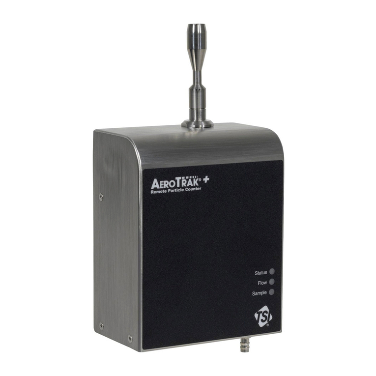
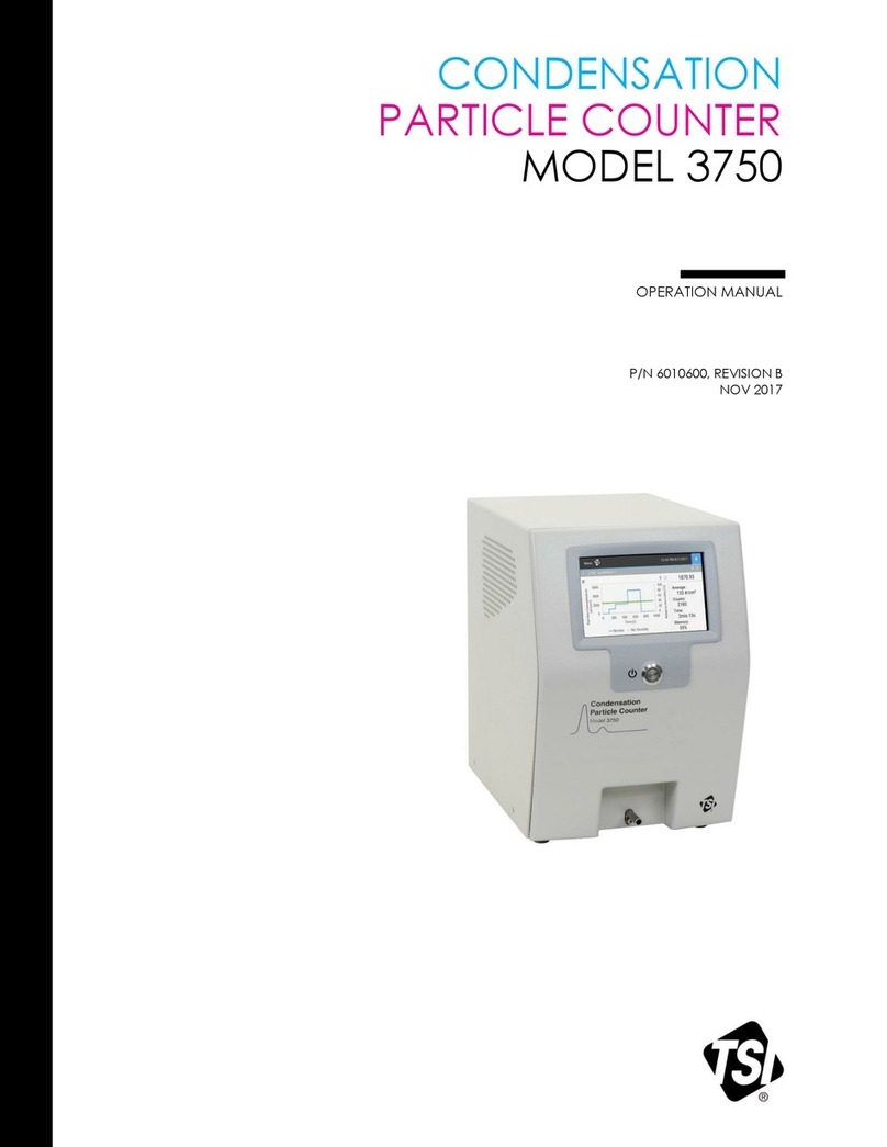
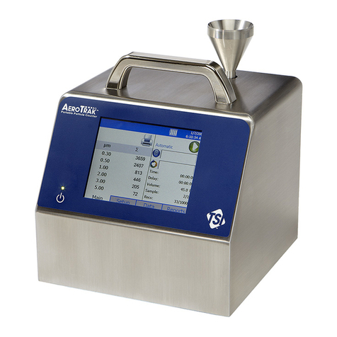
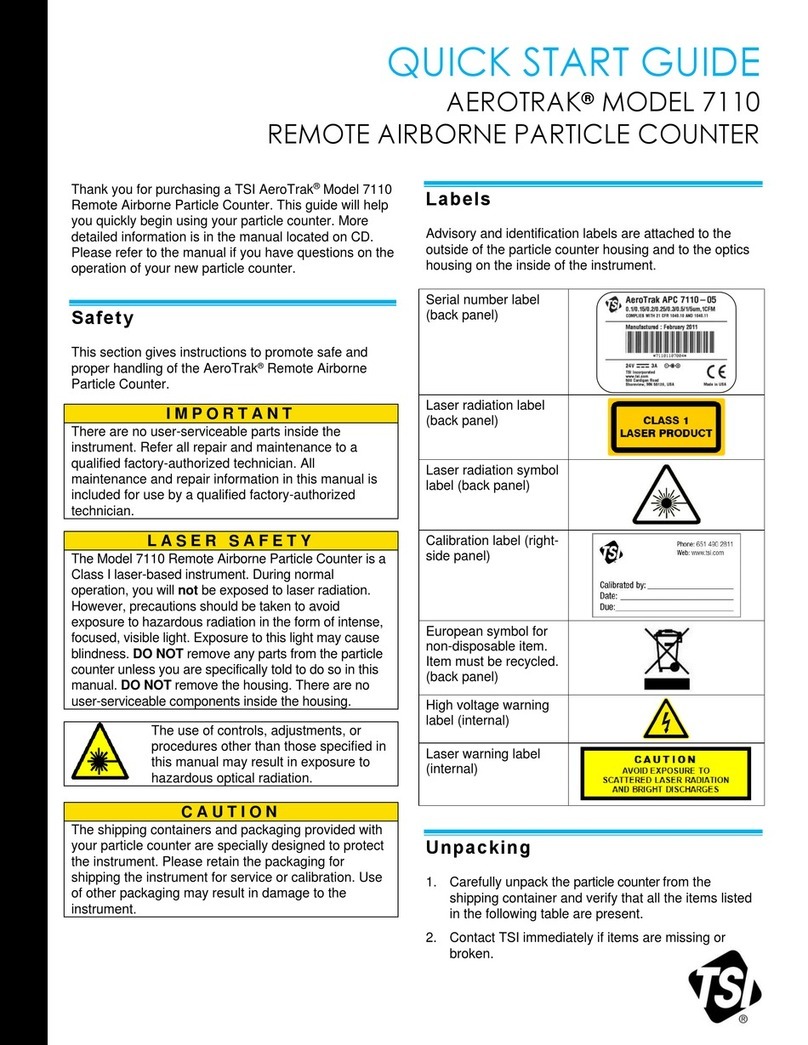
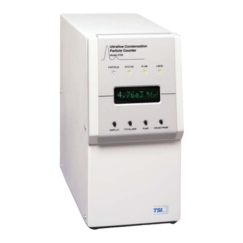
TSI Instruments 3022A User manual

Particle Instruments
Model 3022A
Condensation Particle
Counter
Instruction Manual
P/N 1933763, Revision I
August 2002


Introduction 1
Model 3022A
Condensation Particle
Unpacking and
Setting Up 2
Counter Operation and
Display 3
Instruction Manual Configuring the CPC 4
Technical
Description 5
Particle Counting 6
Calibrating the CPC 7
Computer Interface
and Commands 8
Maintenance and
Service 9
Applications 10
Appendixes

Manual History
ii
The following is a manual history of the Model 3022A Condensation
Particle Counter Instruction Manual (Part Number 1933763).
Revision Date Revision Date
Preliminary October 1992 ENovember 1996
Final November 1992 F March 1998
A January 1993 September 1998
B December 1993 G July 2000
C June 1994 H July 18, 2000
D May 1996 I July 2002
! The Model 3022A Condensation Particle
Counter instruction manual (P/N
1933763) was originally published as a
Model 3022 Condensation Particle Counter
(P/N 1933022) in September 1988.
Changes have been made throughout the
manual to reflect the model number and
engineering changes.
! Revision A reflects changes to the table in
Chapter 4, a new safety label, inclusion of
ampere ratings (Figure 3-2 and
“Specifications”), and some minor
corrections throughout the manual.
! Revision B includes a revision to Table 2-
1, changes amount of particles from 0.01
to .007 on page 1-1, revises the Customer
Service telephone number, and updates
drawing 9060266 in Appendix D to
Revision F.
! Revision C adds Figure 7-1 showing the
setup for photometric calibration mode,
revises Figure 9-6, and revises schematic
9060265.
! Revision D updates TSI’s “Limitation of
Warranty and Liability” on page iii.
! Revision E adds European Community
“CE Mark” standards, revisions to Chapter
2, “Changing the Line Voltage
Configuration” and “Changing Fuses,”
updates drawing 9060266 in Appendix D
to Revision I, and minor changes were
made to rest of manual.
! Revision F revises minimum particle size
from .008 µm to .007 µm in Table B-1.
! In September 1998, TSI’s area code was
changed from 612 to 651.
! In Revision G, the fuse rating in Table B-1
was corrected to read 100/120V ~
2.0A/250V.
! In Revision H, TSI’s Limitation of Warranty
and Liability was updated.
! In Revision I, TSI’s phone numbers and
address were updated and reference to
CPCount Software was changed to refer to
Aerosol Instrument Manager Software for
CPC and EAD. Appendix D was removed.

iii
Part Number 1933763 / Revision I / August 2002
Copyright ©TSI Incorporated / November 1992–2002 / All rights reserved.
Address TSI Incorporated / 500 Cardigan Road / St. Paul, MN 55126 / USA
Fax No. 651-490-3824
Limitation of Warranty
and Liability
(effective July 2000)
Seller warrants the goods sold hereunder, under normal use and service as
described in the operator's manual, shall be free from defects in workmanship and
material for (12) months, or the length of time specified in the operator's manual,
from the date of shipment to the customer. This warranty period is inclusive of any
statutory warranty. This limited warranty is subject to the following exclusions:
a. Hot-wire or hot-film sensors used with research anemometers, and certain other
components when indicated in specifications, are warranted for 90 days from
the date of shipment.
b. Parts repaired or replaced as a result of repair services are warranted to be free
from defects in workmanship and material, under normal use, for 90 days from
the date of shipment.
c. Seller does not provide any warranty on finished goods manufactured by others
or on any fuses, batteries or other consumable materials. Only the original
manufacturer's warranty applies.
d. Unless specifically authorized in a separate writing by Seller, Seller makes no
warranty with respect to, and shall have no liability in connection with, goods
which are incorporated into other products or equipment, or which are modified
by any person other than Seller.
The foregoing is IN LIEU OF all other warranties and is subject to the LIMITATIONS
stated herein. NO OTHER EXPRESS OR IMPLIED WARRANTY OF FITNESS FOR
PARTICULAR PURPOSE OR MERCHANTABILITY IS MADE.
TO THE EXTENT PERMITTED BY LAW, THE EXCLUSIVE REMEDY OF THE USER
OR BUYER, AND THE LIMIT OF SELLER'S LIABILITY FOR ANY AND ALL LOSSES,
INJURIES, OR DAMAGES CONCERNING THE GOODS (INCLUDING CLAIMS BASED
ON CONTRACT, NEGLIGENCE, TORT, STRICT LIABILITY OR OTHERWISE) SHALL
BE THE RETURN OF GOODS TO SELLER AND THE REFUND OF THE PURCHASE
PRICE, OR, AT THE OPTION OF SELLER, THE REPAIR OR REPLACEMENT OF THE
GOODS. IN NO EVENT SHALL SELLER BE LIABLE FOR ANY SPECIAL,
CONSEQUENTIAL OR INCIDENTAL DAMAGES. SELLER SHALL NOT BE
RESPONSIBLE FOR INSTALLATION, DISMANTLING OR REINSTALLATION COSTS
OR CHARGES. No Action, regardless of form, may be brought against Seller more
than 12 months after a cause of action has accrued. The goods returned under
warranty to Seller's factory shall be at Buyer's risk of loss, and will be returned, if at
all, at Seller's risk of loss.
Buyer and all users are deemed to have accepted this LIMITATION OF WARRANTY
AND LIABILITY, which contains the complete and exclusive limited warranty of
Seller. This LIMITATION OF WARRANTY AND LIABILITY may not be amended,
modified or its terms waived, except by writing signed by an Officer of Seller.
Service Policy Knowing that inoperative or defective instruments are as detrimental to TSI as they
are to our customers, our service policy is designed to give prompt attention to any
problems. If any malfunction is discovered, please contact your nearest sales office
or representative, or call TSI’s Customer Service department at 1-800-874-2811
(USA) or 651-490-2811.

iv Model 3022A Condensation Particle Counter

Safety
v
This section gives instructions to promote safe and proper
operation of the Model 3022A Condensation Particle Counter (CPC),
samples of warnings found in this manual, and labels attached to
the instrument.
Laser Safety
The Model 3022A Condensation Particle Counter is a Class I laser-
based instrument. During normal operation, you will not be
exposed to laser radiation. However, you must take certain
precautions or you may expose yourself to hazardous radiation in
the form of intense, focused invisible light. Exposure to this light
can cause blindness.
Take these precautions:
#Do not remove any parts from the CPC unless you are
specifically told to do so in this manual.
#Do not remove the CPC housing while power is supplied to the
instrument.
WARNING
The use of controls, adjustments, or procedures other than those specified in
this manual may result in exposure to hazardous optical radiation.
Chemical Safety
The Model 3022A CPC uses n-butyl alcohol (butanol) as a working
fluid. Butanol is flammable. Butanol is also toxic if inhaled. Refer to
a Material Safety Data Sheet for butanol and take these
precautions:
#Use butanol only in a well-ventilated area.
#Butanol vapor is identified by its characteristically strong odor
and can easily be detected. If you smell butanol and develop a
headache, or feel faint or nauseous, leave the area at once.
Ventilate the area before returning.

vi Model 3022A Condensation Particle Counter
!
Caution
Butanol is flammable. Butanol is also potentially toxic if inhaled. Use butanol
only in a well-ventilated area. If you smell butanol and develop a headache, or
feel faint or nauseous, leave the area at once. Ventilate the area before
returning.
!
WARNING
Although the CPC is appropriate for monitoring inert process gases such as
nitrogen or argon, it should not be used with hazardous gases such as hydrogen
or oxygen. Using the CPC with hazardous gases may cause injury to personnel
and damage to equipment.
Description of Safety Labels
This section acquaints you with the advisory and identification
labels on the instrument and used in this manual to reinforce the
safety features built into the design of the instrument.
Caution
!
Caution
Caution means be careful. It means if you do not follow the procedures
prescribed in this manual you may do something that might result in equipment
damage, or you might have to take something apart and start over again. It also
indicates that important information about the operation and maintenance of this
instrument is included.
Warning
!
WARNING
Warning means that unsafe use of the instrument could result in serious injury to
you or cause irrevocable damage to the instrument. Follow the procedures
prescribed in this manual to use the instrument safely.

Safety vii
Caution or Warning Symbols
The following symbols may accompany cautions and warnings to
indicate the nature and consequences of hazards:
Warns you that uninsulated voltage within the instrument may have
sufficient magnitude to cause electric shock. Therefore, it is
dangerous to make any contact with any part inside the instrument.
Warns you that the instrument contains a laser and that important
information about its safe operation and maintenance is included.
Therefore, you should read the manual carefully to avoid any
exposure to hazardous laser radiation.
Warns you that the instrument is susceptible to electro-static
dissipation (ESD) and ESD protection procedures should be
followed to avoid damage.
Indicates the connector is connected to earth ground and cabinet
ground.

viii Model 3022A Condensation Particle Counter
Labels
Advisory labels and identification labels are attached to the outside
of the CPC housing and to the optics on the inside of the
instrument.
Figure 1 shows the internal and external labels for the
Model 3022A CPC.
a.
500 CARDIGAN ROAD
ST. PAUL, MINNESOTA
MADE IN U.S.A. 55126
MODEL
SERIAL
DATE
TSI
®
b.
INVISIBLE LASER RADIATION
WHEN OPEN. AVOID DIRECT
EXPOSURE TO BEAM.
DANGER
Figure 1
Advisory Labels: (a) identification label (on the back panel); (b) warning label (on
the optics housing)

Contents
ix
Manual History.............................................................................ii
Safety ........................................................................................... v
Laser Safety ............................................................................. v
Chemical Safety ....................................................................... v
Description of Safety Labels .................................................... vi
Caution................................................................................ vi
Warning ............................................................................... vi
Caution or Warning Symbols............................................... vii
Labels....................................................................................viii
About This Manual......................................................................xv
Purpose...................................................................................xv
Organization ...........................................................................xv
Related Product Literature ....................................................xvii
Submitting Comments ..........................................................xvii
Chapters
1 Introduction.........................................................................1-1
Product Description ..............................................................1-1
Features................................................................................1-2
Applications..........................................................................1-2
2 Unpacking and Setting Up...................................................2-1
Packing List ..........................................................................2-1
Unpacking Instructions......................................................2-1
Initial Setup..........................................................................2-2
Protective Caps ..................................................................2-2
Checking the Line Voltage Configuration............................2-2
Changing the Fuse .............................................................2-4
Changing Between European and American-Style
Fuses ..............................................................................2-4
Mounting the Bottle Bracket ..............................................2-6
Filling the Bottle with Fluid................................................2-7
Changing the Inlet..............................................................2-7
Applying Power to the CPC...............................................2-12
3 Operation and Display.........................................................3-1
Front Panel Functions...........................................................3-1
Warmup Mode....................................................................3-2

x Model 3022A Condensation Particle Counter
Primary Functions..............................................................3-2
Pump ..............................................................................3-2
Display............................................................................3-3
Total................................................................................3-3
Clear ...............................................................................3-3
Range..............................................................................3-4
Secondary Functions..........................................................3-4
Shift................................................................................3-4
Status .............................................................................3-4
Drain/Fill........................................................................3-5
Flow Hi/Lo ......................................................................3-6
Indicator Lights..................................................................3-6
Particle............................................................................3-7
Flow ................................................................................3-7
Auto ................................................................................3-7
Optics, Condenser, Saturator ..........................................3-7
Laser...............................................................................3-7
Liquid Level.....................................................................3-7
Back Panel Functions ...........................................................3-8
COM PORT.........................................................................3-8
Analog Output....................................................................3-8
Mux Output .......................................................................3-9
Pulse Output......................................................................3-9
Liquid Supply.....................................................................3-9
Makeup Air ........................................................................3-9
Pump Exhaust ...................................................................3-9
Liquid Drain.....................................................................3-10
Operating Specifications and Precautions ...........................3-10
Ambient Temperature.......................................................3-10
Inlet Pressure...................................................................3-10
High Flow Mode................................................................3-10
Low Flow Mode.................................................................3-11
Moving the Counter..........................................................3-11
Drying the Counter ..........................................................3-11
First Method..................................................................3-12
Second Method..............................................................3-12
4 Configuring the CPC............................................................4-1
Enabling the Configuration Mode..........................................4-1
Running the Configuration Function..................................4-3
Flow Calibration....................................................................4-6
Condenser Flow Calibration ...............................................4-7

Contents xi
5 Technical Description .........................................................5-1
Theory...................................................................................5-1
Historical Notes.....................................................................5-2
Adiabatic Expansion CNC ..................................................5-3
Two-Flow Mixing CNC ........................................................5-3
Diffusional Thermal CNC....................................................5-3
Design of the CPC .................................................................5-4
Sensor................................................................................5-5
Microprocessor...................................................................5-7
Flow System..........................................................................5-7
High Flow...........................................................................5-8
Low Flow............................................................................5-8
Filters and Restrictors........................................................5-9
Flowmeter ..........................................................................5-9
Pump ...............................................................................5-10
6 Particle Counting.................................................................6-1
Optical Detection ..................................................................6-1
Single-Particle, Realtime Counting ........................................6-1
Total Count Accuracy............................................................6-3
Single-Particle, Live-Time Counting.......................................6-4
Photometric Calibration ........................................................6-4
Autoranging..........................................................................6-5
7 Calibrating the CPC.............................................................7-1
8 Computer Interface and Commands...................................8-1
Computer Interface ...............................................................8-1
Pin Connectors...................................................................8-1
Baud Rate..........................................................................8-2
Parity .................................................................................8-2
Computer Commands...........................................................8-3
BASIC Program: TSICPC .......................................................8-6
9 Maintenance and Service....................................................9-1
Changing the Filters..............................................................9-1
HEPA Filter ........................................................................9-1
Tube Filter .........................................................................9-1
Pump Exhaust Filter (DQ) ..................................................9-4
Checking the CPC for Leaks..................................................9-4
Installing an EPROM.............................................................9-6
Failures.................................................................................9-9
Technical Contacts..............................................................9-10
Returning the CPC for Service.............................................9-11

xii Model 3022A Condensation Particle Counter
10 Applications.......................................................................10-1
Clean Air.............................................................................10-1
Using the CPC With a Multiplexer/Processor ......................10-1
Testing Filter Efficiency.......................................................10-2
Using the CPC With a Diffusion Battery ..............................10-2
Differential Mobility Particle Sizer........................................10-3
Appendixes
A References ...........................................................................A-1
B Specifications....................................................................B-1
C Technical Papers ...............................................................C-1
E Calibration and Data Sheets.............................................D-1
F Software Disk.....................................................................E-1
Figures
1 Advisory Labels: (a) identification label (on the back panel); (b)
warning label (on the optics housing) ...............................viii
1-1 TSI Model 3022A Condensation Particle Counter................1-1
2-1 Power Entry, Fuse, and Voltage Module..............................2-3
2-2 Orientation of the Voltage Selector Card .............................2-3
2-3 North American–Fusing Arrangement.................................2-5
2-4 European–Fusing Arrangement ..........................................2-5
2-5 Fuse Block/Cover Assembly...............................................2-5
2-6 Mounting the Bottle Bracket: (a) Bottle Bracket; (b) Screw,
8-32 ×3/8 Phillips Pan-head Lockwasher, #8 Internal
Tooth; (c) CPC Back Panel ...............................................2-6
2-7 Removing the Front Inlet Tube; (a) Pull Inlet Tube Out;
(b) Loosen Swagelok Nuts, 2 Places .................................2-8
2-8a Back Inlet Option for Positioning the Inlet Tube..................2-9
2-8b Front Inlet Option for Positioning the Inlet Tube...............2-10
2-8c Side Inlet Option for Positioning the Inlet Tube .................2-11
2-8d Side Inlet Option with the 2.8-in. Inlet Tube.....................2-12
3-1 CPC Front Panel.................................................................3-1

Contents xiii
3-2 CPC Back Panel..................................................................3-8
3-3 Saturator: (a) Front of Counter; (b) End Plate With
Four Screws ..................................................................3-13
3-4 Saturator: (a) Front of Counter; (b) Wick; (c) Fill Sensor
Connector; (d) End-Plate (Removed); (e) Inlet Flow;
(f) Fluid Line..................................................................3-14
4-1 Location of PC Boards and Potentiometers .........................4-1
4-2 Setting the Configuration Switch to Enable the
Configuration Mode.........................................................4-2
5-1 Drawing of the CPC Sensor.................................................5-6
5-2 Flow Schematic of the CPC.................................................5-8
6-1 Typical Digital Pulse Trace From the Photodetector ............6-2
7-1 Calibration of the Condensation Particle Counter ...............7-1
7-2 Dilution Bridge Used for High-Concentration Particles........7-2
8-1 Connector Pin Designations................................................8-1
9-1 Locating the Filter Plug on the Bottom of the CPC:
(a) Power Supply PC Board; (b) Filter Plug;
(c) Front Panel.................................................................9-2
9-2 Replacing the Filter Tube: (a) Filter.....................................9-3
9-3 Checking for Leaks With a Vacuum....................................9-5
9-4 Checking for Leaks With Compressed Air ...........................9-6
9-5 Model 3022A CPC Screw Locations.....................................9-8
9-6 EPROM Location on the Model 3022A CPC Display
Board ..............................................................................9-8
10-1 CPC, Diffusion, Battery and Switching Valve System
for Measuring the Size Distribution of Aerosols Below
0.2 Micrometer in Diameter...........................................10-3
10-2 Schematic of the DMPS/CPC in the Underpressure
Mode.............................................................................10-4
Tables
2-1 Model 3022A CPC Packing List...........................................2-1
6-1 Coincidence Correction for Concentrations up to
1000 Particles/cm3.........................................................6-3
8-1 Signal Connections for RS-232 Configurations ...................8-2
8-2 Computer Commands.........................................................8-3

xiv Model 3022A Condensation Particle Counter
9-1 Troubleshooting CPC Problems.........................................9-10
B-1 Specifications of the Model 3022A CPC ............................B-1

About This Manual
xv
Purpose
The Model 3022A Condensation Particle Counter (CPC) instruction
manual is written for both the installer and the operator, whether a
technician or the head of a research laboratory.
Organization
The ten chapters of this manual describe the CPC and explain how
to set up, operate, and maintain it.
#Chapter 1: Introduction
This chapter serves as an introduction to the Model 3022A
Condensation Particle Counter.
#Chapter 2: Unpacking and Setting Up
This chapter describes the step-by-step procedure for getting
the CPC ready to operate.
#Chapter 3: Operation and Display
This chapter describes all of the features and controls that run
the CPC, including the front-panel functions and controls, the
back-panel components, and some operating specifications and
precautions.
#Chapter 4: Configuring the CPC
This chapter describes a feature that allows you to set up and
select certain functions and outputs controlled by the internal
microprocessor. Read this chapter to learn how to enter into the
configuration mode.
#Chapter 5: Technical Description
This chapter details the principle of operation and theory of the
condensation nucleus counter.
#Chapter 6: Particle Counting
This chapter describes how the CPC counts and averages data,
and displays the particle concentration.

xvi Model 3022A Condensation Particle Counter
#Chapter 7: Calibrating the CPC
This chapter describes the method used at TSI for calibrating
the CPC’s photometric particle concentration mode.
#Chapter 8: Computer Interface and Commands
This chapter describes the computer interface hardware and
associated software commands. Included is a simple program
written in BASIC that demonstrates how to communicate with
the CPC.
#Chapter 9: Maintenance and Service
This chapter describes the recommended practices and
schedule for routine cleaning, checking and calibration.
#Chapter 10: Applications
This chapter describes some typical applications of the CPC
including the Differential Mobility Particle Sizer (DMPS),
Diffusion Battery, and filter testing.
#Appendix A: References
This appendix lists all of the references that have been used
within the text of the manual. In addition, a general list of
references pertaining to condensation nucleus or particle
counters is included.
#Appendix B: Specifications
This appendix lists the specifications of the Model 3022A
Condensation Particle Counter.
#Appendix C: Technical Papers
This appendix includes two technical papers.
#Appendix D: Calibration and Data Sheets
This appendix contains calibration and data sheets used for the
Model 3022A CPC.
#Appendix E: Software Disks
This appendix contains the software disks for the BASIC
program provided with the Model 3022A CPC.

About this Manual xvii
Related Product Literature
#Model 376060 Particle Size Selector Instruction Manual
(part number 1930013) TSI Incorporated
This manual contains operating instructions for the Model
376060 Particle Size Selector, an accessory for the Model 3022A
CPC. The Model 376060 is a separating device that removes
small particles from an aerosol while passing larger particles.
❑Aerosol Instrument Manager®Software for CPC and EAD
Instruction Manual (part number 1930062) TSI Incorporated
This manual contains operating instructions for Aerosol
Instrument Manager®Software for CPC and EAD, a software
program that monitors, calculates, and displays particle data
collected by a CPC.
Submitting Comments
TSI values your comments and suggestions on this manual. Please
use the comment sheet on the last page of this manual to send us
your opinion on the manual’s usability, to suggest specific
improvements, or to report any technical errors.
If the comment sheet has already been used, please send your
comments to:
TSI Incorporated
Particle Instruments
500 Cardigan Road
St. Paul, MN 55126
Fax: (651) 490-3824

xviii Model 3022A Condensation Particle Counter
Table of contents
Other TSI Instruments Cash Counter manuals

TSI Instruments
TSI Instruments AEROTRAK+ 7201 User manual

TSI Instruments
TSI Instruments AEROTRAK 9310 User manual

TSI Instruments
TSI Instruments AEROTRAK 9310 User manual

TSI Instruments
TSI Instruments AeroTrak 8220 User manual

TSI Instruments
TSI Instruments 3786 Operation manual

TSI Instruments
TSI Instruments AEROTRAK 9306 User manual

TSI Instruments
TSI Instruments AEROTRAK 7201-A2F User manual

TSI Instruments
TSI Instruments AEROTRAK 7110 User manual

TSI Instruments
TSI Instruments 3750 User manual

TSI Instruments
TSI Instruments AEROTRAK 9306 User manual