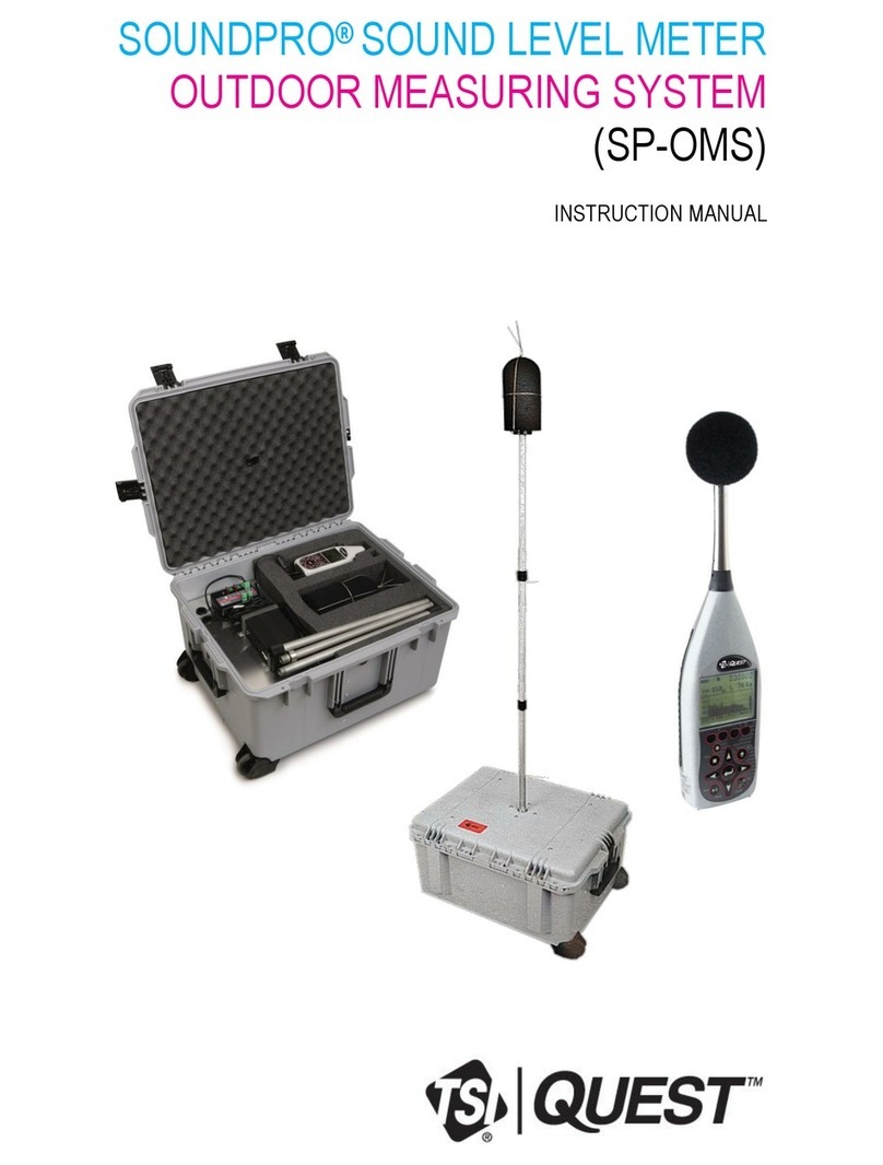
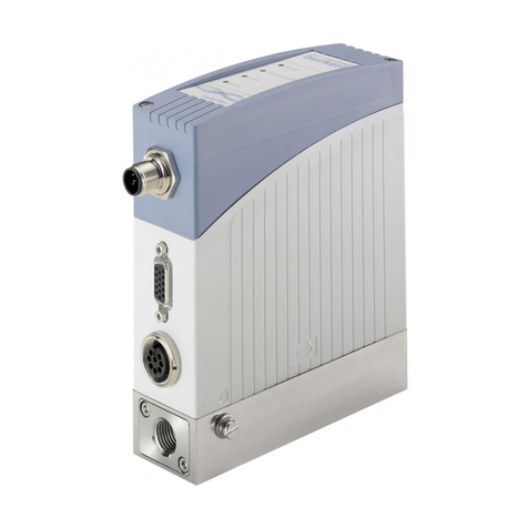
TSI Quest EVM-7 User manual

ENVIRONMENTAL MONITOR
EVM SERIES
USER MANUAL


Dangers, Warnings, & Cautions
EVM Series User Manual
iii
ENVIRONMENTAL MONITOR
EVM SERIES
Dangers, Warnings, & Cautions
DANGER!
Failure to observe the following procedures may result in serious personal injury:
Not for use in Explosive or Hazardous locations. This product is NOT Intrinsically Safe.
Contains built-in lithium ion battery pack. DO NOT incinerate or dispose of in fire.
DO NOT disassemble, alter, or re-construct the li-ion battery.
Contains Class 3B visible laser radiation source (658 nm, nominal 5 mW). DO NOT look
directly into beam or view with telescopic devices.
This instrument will NOT detect natural gas.
WARNING!
Read the manual before operation.
DO NOT store in temperatures exceeding 60°C (140°F) and in direct sunlight.
DO NOT immerse in liquids.
The Sensors and batteries in this instrument have limited shelf-life, even if never used.
DO NOT disassemble, service, or clean the optical engine internal components while power is
applied. The laser source can hurt you.
Caution!
General
Condensation may damage your instrument and its sensors.
A non-condensing environment is required for proper measurements.
DO NOT charge batteries outside the range of 0°C to 40°C (32°F to 104°F).
Battery run-time may be somewhat reduced at lower than 20°C (68°F) temperatures.
Caution!
Temp/RH/Dew Point
The internal Temp/RH sensor in this instrument is not designed for use in bright sunlight or in the
presence of a strong radiant heat sources. It is intended primarily for indoor use. It is not equivalent
to a protected dry-bulb thermometer.

Dangers, Warnings, & Cautions
EVM Series User Manual
iv
Caution!
PM/dust
Clean the optical engine mirror with a soft cloth, if it is dirty. Scratches will affect performance.
Avoid measuring wet particles, fogs, and liquid mists that will tend to cling to the impactor,
optical engine, tubing, and pump surfaces.
Avoid oily mists as found near some machining operations.
This monitor is designed to measure dry particulates, not filaments.
DO NOT attempt to measure Asbestos with this instrument.
Keep a "Pump Protection Filter" or other gravimetric filter in place to help prolong the life of the
pump.
You must check and calibrate the flow rate, when using this device as a (gravimetric) sampling
pump.
Caution!
CO2
Avoid exposure to condensation, fogs, and liquid mists that can contaminate the optical path inside
the CO2sensor.
Caution!
PID
This instrument cannot detect methane gas.
For best sensor life, avoid acidic condensing gases.
The presence of moisture can affect performance of the PID.
Caution!
Toxic
Beware of certain cross-sensitivities when measuring toxic gas levels. Readings can be
nonspecific in the presence of certain cross-contaminant gases.
Caution!
ir velocity
The tip of the Air velocity probe is very fragile.

Dangers, Warnings, & Cautions
EVM Series User Manual
v
FCC Compliance Statement
This equipment has been tested and found to comply with the limits for a Class B digital device,
pursuant to Part 15 of the FCC rules. These limits are designed to provide reasonable protection
against harmful interference when the equipment is operated in a commercial or residential
environment. This equipment generates, uses and can radiate radio frequency energy and, if not
installed and used in accordance with the instruction manual, may cause harmful interference to
radio communications. If harmful interference occurs, the user will be required to correct the
interference at his or her expense.


Table of Contents
EVM Series User Manual
vii
Table of Contents
Dangers, Warnings, & Cautions.......................................iii
Table of Contents..............................................................vii
Introduction......................................................................... 1
Particulate Sampling (Aerosols/Dust Vapors) ................. 2
Particulate Path ...............................................................2
Particulate Sizes..............................................................3
Particulates and Cut-Point...............................................4
Collecting/Sensing the Particulates.................................4
Gravimetric Sampling ......................................................4
Pump ...............................................................................4
Gas Sensors Sampling....................................................... 4
Gas Sensors and Path ....................................................5
Volatile Organic Compounds (VOCs) Sampling.............. 6
Temperature, Relative Humidity, Dew Point .................... 6
What the Standards Say..................................................... 6
Resources .......................................................................7
EVM Series .......................................................................... 8
Applications .....................................................................8
Models Explained ............................................................9
Getting Started..................................................................11
Checking the Equipment..................................................11
Display and Keypad..........................................................12
Diagram.........................................................................12
Keypad description........................................................12
Turning on .........................................................................13
Start Screen Explanation...............................................13
Navigating......................................................................14
Indicators/Icons on the display......................................14
Turning Off ........................................................................ 15
Instrument Information ....................................................15
Unit Information Screen.................................................15
TSI Detection Management Software DMS .................... 17
Communicating................................................................. 17
Powering and Outputs on the EVM ...............................17
Battery......................................................................17
Charging...................................................................18
Outputs.....................................................................18
Setting up the Environmental Monitor............................ 19
Setting up Parameters via the Keypad ...........................19
Time and Date Setting...................................................19
Checking Battery Power................................................20
Display: Language, Contrast, and Key Click.................22
Setting Logging and Viewing Run Time ........................23
PID Sensor Setup..........................................................25
Changing Units (Temperature, Particulates, PID,
and Air Velocity) .........................................................27
Setting up Particulate Settings ......................................27
Setting Profiles (Particulate Correction Factors) ...........28
How Particulate Factors are Adjusted and Calculated..28
Dust Correction Factors (Profiles)............................28
Particulate Pump: Enable or Disable.............................30
Resetting the Gravimetric Filter.....................................30
Auxiliary Input/Output ....................................................31
Digital Output ...........................................................31
Air Velocity.....................................................................33
Analog-out .....................................................................33
Restoring Default Factory Settings................................34
Backlight Setting............................................................36
Resetting the EVM.........................................................36
Lock/Secure Run and/or Setup .....................................36
Unlock run and/or setup ................................................38
Auto-run.........................................................................38
Auto-run and timed-run mode ..................................38
Auto-Run with Date Mode........................................39
Auto-Run with Day of Week (DOW) Mode...............40
Calibrate Sensors .............................................................43
Placement and Calibration of Sensors...........................43
Calibrating sensors include: ..........................................43
Inserting and Removing Sensors ..................................43
Calibrating Particulates..................................................44
Impactor and use...........................................................45
Adjusting the Impactor/Turret Setting............................46
Particulates Calibration (Zero Cal) ................................47
Particulate Advanced Calibration (Gravimetric) ............51
Gravimetric Calibration Overview ............................52
Performing a Gravimetric Calibration ............................52
Pump Flow Rate Calibration..........................................53
Toxic Gas Sensors ........................................................54
Cross Sensitivity ............................................................55
How Sensors Operate..............................................55
Quality Calibrations .......................................................55
About Sensors and Cal Storage....................................55
Calibration History and Sensor Serial Numbers............55
Applying a Gas Sensor..................................................56
Calibrating Toxic Gas Sensors......................................56
Toxic Gas Zero Calibration ......................................57
Ozone Calibration for Zero and Span ......................57
Toxic Gas Span Calibration .....................................59
Calibrating CO2 AND O2................................................60
O2 Accuracy..............................................................60
Table of Contents

Table of Contents
EVM Series User Manual
viii
Calibrating Photo-Ionization Detector (PID) Sensor......63
PID parts per million (ppm) zero calibration.............63
PID parts per billion (ppb) zero calibration...............63
PID Span Calibration ...............................................64
Calibrating Relative Humidity and Temperature ...........66
Calibration History .........................................................67
Verify Calibration and Drifting Analysis .........................68
Measuring and Viewing.................................................... 71
Overview of Running a Session......................................71
Quick Help.....................................................................71
Measuring..........................................................................71
Understanding What Data is Stored..............................72
Summary Data .........................................................72
Logged Data/Time History.............................................72
Running and Stopping...................................................73
Measurement Screens and Navigation........................... 74
Unit defined ...................................................................74
About the Measurement Soft Keys................................75
Particulate Measurement Screen ....................................76
Impactors and Particulate Measuring............................76
Extending Run-Time for PM Measurements .................76
Changing Particulate Measurements ............................77
Relative Humidity and Temperature Measurements ..... 78
Relative Humidity and Temperature Screen .................78
Gas Measurements........................................................... 79
Gas Screen....................................................................79
Composite Measurement .................................................80
Composite Screens .......................................................80
Air Velocity Meaursurement Screen ...............................81
Summary Data................................................................... 82
Viewing Details in the Measurement Screen ................82
Trend Data .........................................................................83
Viewing trend data in the measurement screen............83
Past Session...................................................................... 84
Summary Data Screen ..................................................84
File System Menu ............................................................. 86
Deleting Sessions Individually.......................................86
Delete All Sessions .......................................................87
Memory Remaining and File Properties........................88
Estimated Run Time......................................................89
Detection Management Software ....................................91
Environmental Monitor Communication ........................91
Downloading Data with the EVM ..................................... 93
EVM: Viewing Data ...........................................................93
Selecting a session/study..............................................93
EVM Panel Layout View (PLV) Page ............................94
EVM Reports and Printing................................................96
Customizing Reports .....................................................97
EVM Setup ....................................................................98
Saving and Sending Configurations.........................98
General EVM Setup.......................................................99
EVM General Parameters Table..............................99
EVM and Logging Settings..........................................100
EVM Logging Parameters Table............................101
EVM and Auto-Run Setting .........................................101
Timed-Run and Auto-Run Setting..........................102
Date and Auto-Run Setting ....................................102
Day of Week and Auto-Run Setting .......................103
EVM and Security Settings..........................................104
EVM and Triggering Settings.......................................104
EVM and Particulate Settings......................................106
EVM and Particulates Setup ..................................106
EVM Firmware Update ................................................107
Maintenance and Cleaning.............................................109
Overview ..........................................................................109
PID Sensor ..................................................................109
Removing and Installing PID Sensor...........................110
Maintenance and Cleaning Overview of PID...............111
Cleaning PID Sensor...................................................111
Optical Engine: Maintenance and Cleaning................113
Impactor Care..................................................................116
Impactors and When To Clean....................................117
Gravimetric Cassette and Filter Paper..........................117
Specifications..................................................................119
Particulate Sensor ..........................................................119
Volatile Organic Compounds (VOCs) Gas
Detector (PID Sensor).....................................................119
Carbon Dioxide Sensor ..................................................120
Relative Humidity Sensor...............................................120
Temperature Sensor.......................................................120
Toxic Gas Sensors..........................................................121
Air Velocity Accessory (Optional –Air Probe 10)........121
Displayed Data ................................................................121
Electrical Characteristics...............................................122
Environmental effects ....................................................122
Physical characteristics.................................................122
Measurements units .......................................................122
Operating Modes.............................................................123
Time Constants ...............................................................123
Special Functions ...........................................................123

Table of Contents
EVM Series User Manual
ix
Estimated Logged Run Times ....................................... 124
Standard EVM-7 (Memory and logged time)...............124
Standard EVM-4 (Memory and logged time)...............125
Standard EVM-3 (Memory and logged time)...............127
Accessories: Replacement and Optional Parts........... 128
Customer Service ...........................................................131
Technical Support Contacts ..........................................131
Service Contact Information.......................................... 131
Returning for Service .....................................................132
Calibration .......................................................................132
Warranty ..........................................................................133
Glossary of Terms .......................................................... 135
Appendix C......................................................................141
PID sensor and correction factors tables ....................141
Appendix D......................................................................151
Frequently Asked Questions (FAQs)............................151
Particulate Measurements...........................................151
Gravimetric Sample (optional for particulate
calibration)................................................................153
Toxic Sensor Measurements.......................................154
Pump/Airflow Measurements.......................................155
Digital Output (using stereo plug & diagram) ..............156
PID Questions (for Volatile organic compound
measurements) ........................................................157
Power...........................................................................158
Alarm Outputs..............................................................158
General: Mechanical....................................................159
CO2Sensor and how to reorder ..................................159
CO2Sensor and how to reorder (continued) ...............160
Calibrating Sensors .....................................................160
Appendix E ......................................................................163
System Errors Displayed on the EVM Series...............163
INDEX ...............................................................................165
List of Figures
Figure 1-1: Particulate path diagram .................................... 2
Figure 1-2: Particulates and diameter size ........................... 3
Figure 2-1: Identifying your equipment ............................... 11
Figure 2-2: EVM keypad and display explained ................. 12
Figure 2-3: Start screen defined ......................................... 13
Figure 2-4: Unit Information screen .................................... 15
Figure 2-5: Selecting Unit Info. Sensors.............................16
Figure 2-6: Viewing installed sensors.................................16
Figure 2-7: Communicating with DMS via USB cable ........ 17
Figure 2-8: USB, power jack and digital output port ........... 18
Figure 3-1: Time-Date screen parameters ......................... 20
Figure 3-2: Start screen ...................................................... 21
Figure 3-3: Battery screen .................................................. 21
Figure 3-4: Screen display settings .................................... 22
Figure 3-5: Logging screen................................................. 24
Figure 3-6: Estimated run time for logging screen.............. 25
Figure 3-7: PID correction factor......................................... 26
Figure 3-8: PID correction factor displayed on
measurement screens.................................................... 26
Figure 3-9: Units screen ..................................................... 27
Figure 3-10: Edit profiles for dust calibration ...................... 29
Figure 3-11: Entering a profile for particulate calibration.... 29
Figure 3-12: Particulate setup screen................................. 30
Figure 3-13: Configuring digital output................................ 32
Figure 3-14: Air Velocity setting.......................................... 33
Figure 3-15: Analog out results with temperature
as output......................................................................... 33
Figure 3-16: Analog-Out screen ......................................... 34
Figure 3-17: Defaults screen (restoring factory settings).... 34
Figure 3-18: Restoring default calibrations .........................35
Figure 3-19: Backlight key ..................................................36
Figure 3-20: Lock Soft key..................................................37
Figure 3-21: Setting lock/secure .........................................37
Figure 3-22: Selecting auto-run with timed-run mode.........38
Figure 3-23: Setting timed-run and duration .......................39
Figure 3-24: Selecting auto-run with date mode.................39
Figure 3-25: Setting auto-run date mode............................40
Figure 3-26: Setting auto-run DOW mode ..........................41
Figure 4-1: Sensor housing and manifold...........................43
Figure 4-2: Sensors’ locations ............................................44
Figure 4-3: How the impactor functions ..............................45
Figure 4-4: PM2.5 impactor setting example......................46
Figure 4-5: Adjusting impactor/turret setting.......................47
Figure 4-6: Particulate zero cal with HEPA filter.................48
Figure 4-7: Selecting calibration screen .............................48
Figure 4-8: Particulate cal screen .......................................49
Figure 4-9: Particulate calibration and ready screen ..........49
Figure 4-10: Particulate calibration and waiting screen......50
Figure 4-11: Particulate calibration pause screen ..............50
Figure 4-12: Zero Cal set for Particulates...........................51
Figure 4-13: Reset gravimetric setting................................52
Figure 4-14: Pump flow rate calibration ..............................53
Figure 4-15: Flow Rate Calibration .....................................54
Figure 4-16: Calibration history for EVM.............................55
Figure 4-17: Applying a gas sensor ....................................56
Figure 4-18: Selecting sensor for calibration process.........57
Figure 4-19: Calibration zero screen ..................................58
Figure 4-20: Calibration zero pause screen........................58

Table of Contents
EVM Series User Manual
x
Figure 4-21: Span Calibration............................................. 59
Figure 4-22: Saved Calibration screen ............................... 60
Figure 4-23: Selecting a calibration sensor ........................61
Figure 4-24: Calibration CO2 ready screen........................61
Figure 4-25: Setting CO2Span Cal screen......................... 62
Figure 4-26: Saved Calibration ........................................... 62
Figure 4-27: Selecting PID sensor for
calibration process .........................................................63
Figure 4-28: Calibration mode screen ................................ 64
Figure 4-29: PID Calibration Span soft key ........................ 65
Figure 4-30: Saved Calibration screen ............................... 66
Figure 4-31: Temperature calibration .................................67
Figure 4-32: Calibration History screen .............................. 67
Figure 4-33: Calibrate offset verify screen for
PID sensor...................................................................... 68
Figure 4-34: Calibrating PID ............................................... 68
Figure 5-1: Quick help list for running a study .................... 71
Figure 5-2: Sample summary data from DMS reporting..... 72
Figure 5-3: Sample time history data (or logged data)
chart................................................................................ 73
Figure 5-4: Composite measurement screen in
run mode ........................................................................73
Figure 5-5: Example of measurement soft key menus....... 75
Figure 5-6: Particulate Measurement screen .....................76
Figure 5-7: Selecting a measurement calculation ..............77
Figure 5-8: RH and temperature measurement screen...... 78
Figure 5-9: Gas measurement screen................................79
Figure 5-10: Composite measurement screen ................... 80
Figure 5-11: Attaching Air Probe and measuring
Air velocity......................................................................81
Figure 5-12: Details of the composite measurement
screen............................................................................. 82
Figure 5-13: Selecting Trend soft key................................. 83
Figure 5-14: Trend Screen for PM (Dust) ........................... 84
Figure 5-15: Past session screen ....................................... 84
Figure 5-16: Past Session with Files selected....................85
Figure 5-17: Summary screen of a past session ................86
Figure 5-18: Delete session message ................................87
Figure 5-19: Delete all sessions message..........................87
Figure 5-20: File Systems properties screen......................88
Figure 5-21: Viewing estimated run time ............................89
Figure 6: Communicating with the EVM and DMS .............91
Figure 6-1: DMS Start page and Setup/Download
options ............................................................................92
Figure 6-2: EVM and downloading .....................................93
Figure 6-3: Data finder page...............................................94
Figure 6-4: Charts and Graphs (panels) .............................95
Figure 6-5: EVM data in a report format .............................96
Figure 6-6: Customizing DMS reports ................................97
Figure 6-7: Saving and sending EVM setups .....................98
Figure 6-8: General EVM setups ........................................99
Figure 6-9: Logging EVM setups ......................................101
Figure 6-10: EVM Timed-Run Auto-Run setting ...............102
Figure 6-11: EVM Auto-Run with Date setting..................103
Figure 6-12: EVM Auto-Run with Day of Week setting.....103
Figure 6-13: EVM Auto-Run with Day of Week setting.....104
Figure 6-14: EVM Triggering setup...................................105
Figure 6-15: EVM Auto-Run with Day of Week ................106
Figure 7-1: Removing and inserting PID sensor...............110
Figure 7-2: Removing intelligent-sensor casing
with PID ........................................................................111
Figure 7-3: Removing the lamp with removal tool ............112
Figure 7-4: Remove/insert PID sensor with lamp
& pellet..........................................................................112
Figure 7-5: PID sensor cleaning kit...................................112
Figure 7-6: Fitting/Inserting the lamp and pellet ...............113
Figure 7-7: Optical engine and cleaning ...........................114
Figure 7-8: Cleaning the optical engine ............................115
Figure 7-9: When to clean impactors................................117
Figure 7-10: Gravimetric cassette and filter paper
maintenance .................................................................117
List of Tables
Table 2-1: Keypad/user interface explained ....................... 13
Table 2-2: Indicators (i.e., run, stop, battery, Altf ...............14
Table 3-1: Display settings explained.................................22
Table 3-2: Logged intervals and selecting logged
measurements................................................................ 23
Table 3-3: Digital out/Logic settings.................................... 31
Table 4-1: Cross-sensitivity table of interfering gas............55
Table 4-2: Gas calibration soft keys explained...................58
Table 5-1: Unit abbreviations..............................................74
Table 5-2: Measurement soft keys explained.....................75
Table 5-3: Measurement values explained.........................78
Table 5-4: Past session files soft keys explained ...............85

Introduction
Table of Contents
EVM Series User Manual
1
Introduction
The EPA (Environmental Protection Agency) conducted a study over the last 25 years (1975-2000) and
determined that 107 measurable air pollutants, specifically carcinogens, exist in working environments.
Combined with the advent of closed windows, modern office buildings and various cleaning solvents,
the outcome has been energy efficient buildings and homes which contain levels of carcinogens. At high
levels, this is known as “Sick Building syndrome” and can cause acute effects such as headaches,
eye/nose/throat irritation, dry cough or itchy skin, fatigue, and trouble concentrating just to name a few.
Area monitoring or spot checking for high levels of pollutants, such as particulates, VOCs, and toxics,
should be a common practice to ensure good indoor air quality exists in your environment. If poor air
quality is determined, engineering controls such as proper air ventilation and the removal of toxic gases,
would be put into place in order to provide an adequate working/living environment.
The EVM is equipped to measure several different airborne containments or air pollutant applications
including:
Particulate matter sampling (dust monitoring)
Gas sampling
Temperature sampling
Relative Humidity and Dew Point sampling
To get you started quickly with the EVM, the first chapter is dedicated to introducing basic particulate
matter and toxic gas information. The subsequent chapters will guide you through setting up the EVM,
running studies, and assessing your results with easy to follow steps and illustrations.
Caution
The EVM is intended to measure gases that are potentially dangerous to human health. To help
ensure worker safety through the proper use of your unit, it is important that you not only read but
also understand the contents of this manual. Familiarize yourself with the unit before using it in a
potentially hazardous situation.
.
CHAPTER
1

Introduction
Particulate Sampling (Aerosols/Dust Vapors)
EVM Series User Manual
2
Particulate Sampling (Aerosols/Dust Vapors)
The EVM is a portable-area monitoring instrument with a laser-photometer that measures and stores
concentration levels of airborne-dust over time. It is designed to measure and help you identify the air
pollutants, existing as matter (gases and aerosols) in the environment. The methodology used entails a
handful of components including: an air inlet, the impactor (which is the particle size selector), the
collection of particulates, gravimetric sampling, and the pump which are addressed in the upcoming
sections.
Particulate Path
Figure 1-1: Particulate path diagram
(1) TURRET
Air travels though the impactor and the
larger, heavier particulates will stick to
the greased plates within the impactor.
(2) OPTICAL ENGINE
While the pump maintains the flow rate,
the smaller lighter particulates will pass
through the optical engine.
(4) PUMP
The remaining clean/filtered air passes
through the pump.
(3) GRAVIMETRIC CASSETTE
The particulates will collect/trap in the
gravimetric filter/cassettes.
(5) FLOW SENSOR
The clean/filtered air passes through
flow sensor (flow-control orifice hole).
(6) OUTLET
Lastly, it passes through to the Outlet on
the back of the instrument.
❶
❷
❸
❹
❺
❻

Introduction
Particulate Sampling (Aerosols/Dust Vapors)
EVM Series User Manual
3
Particulate Sizes
Aerosols and gases are experienced in industrial processes, workplaces, and in everyday life. Keeping
in mind that inhalable dust is 100 microns and smaller, this dust is usually filtered through the hairs and
membranes in your sinuses. 10 microns and smaller is considered “thoracic”, 4-10 microns is “inhalable”
reaching into your windpipe and other regions, and 4 microns and smaller is “respirable”. These
particulate sizes will represent what you will be measuring.
The figure below identifies different types and sizes of particulates and how it affects the human body.
Gases
and
Aerosols
Defined
-----Liquid: Mist--------------►
-----Solid: Fume---►
◄--------Spray----------------
◄-------Particulates----------
Aerosols and
Particles
Medical
implications
◄---Oil smokes---►
◄-------------
◄---------------
Cement dust-----------►
---Fly ash----------------------
----Tobacco smoke--►
◄--------------
--- Coal dust---------------►
◄---Pollens-------------►
◄--Atmosphere/Airborne--►
inhalable particulates
◄--Wood.►
Dust
◄--Textiles--►
Dust
---------Respirable pm---------►
(inhaled & penetrates the lungs)
---Thoracic pm------------------------►
(inhaled & penetrates the larynx/throat)
----------------------------Inhalable pm------------------►
(inhaled via the nose and /or mouth)
.01 0.1 1 10 100 1000
Particle matter (pm) diameter μm
Figure 1-2: Particulates and diameter size

Gas Sensors Sampling
Particulates and Cut-Point
EVM Series User Manual
4
Particulates and Cut-Point
In consideration of how the size of particulates affect the human body, it is important to select a
particulate size cut-point. Essentially, the particle size selector on the EVM is a top-mounted rotary
impactor. Based on your setting, it will filter out all particulates at or above the selected size. The
instrument has four settings which include 2.5 μm, 4 μm, 10 μm, or none (100 μm). (This is explained in
more detail in Chapter 4.)
Collecting/Sensing the Particulates
Once the impactor setting is selected, the EVM collects (or measures) real-time aerosol/dust
concentration using a 90º optical light scattering photometer to determine the total mass concentration
(in units of mg / m3) of particulate matter. Additionally, gravimetric sampling, a more accurate method, is
also used to determine the mass of particulates.
Gravimetric Sampling
Gravimetric sampling is a type of filtering process in which the
particulates are collected and filtered into the gravimetric
cassette after the dust passes through the optical engine of the
EVM. A user supplied sealed gravimetric cassette can be used
in place of the cassette provided by TSI. The sealed cassette
can be sent to a laboratory for analysis. This testing is typically
used to measure personal exposure to inhalable dust
concentrations.
Pump
The pump is used in the particulate sampling process as a source of air movement so the particulates
are aspirated (or suctioned out) and collected for measurement. The flow rate is 1.67 Liter per minute.
The pump is typically calibrated before each gravimetric sampling.
Gas Sensors Sampling
The EVM uses a unique smart sensor technology includes automatic sensor recognition and measures
up to three gases simultaneously: a selection of optional nine toxic gases, Carbon Dioxide, combustible
gases, and VOCs.

Gas Sensors Sampling
Gas Sensors and Path
EVM Series User Manual
5
Gas Sensors and Path
TSI’s unique smart sensor technology includes automatic sensor recognition, calibration levels,
temperature compensation information and other valuable data that travels with the sensor from one
unit to another.
The following diagram illustrates the gas sensor path for Toxic, CO2, and PID sensors. It also identifies
the temperature sensor for additional analysis/measurements.
Figure 1-3: Gas sensor path illustration
(1) AIR INLET COVER
The path begins with the air pulling
through the air inlet cover.
(2) GAS SENSOR CHAMBERS
The air continues through the gas
sensor bar passing the Toxic, PID, and
CO2sensor chambers.
(3) Fan
It is continuously ventilated by the fan.
(NOTE: When the pump is off, the fan
can be heard near the louvers on the
back cover.)
(4) Temperature sensor
Measures the ambient air temperature.
❹
Temperature sensor
Gas sensor(s) path
❷
❶
Air inlet cover
❸
Fan
Very quiet!

Introduction
Volatile Organic Compounds (VOCs) Sampling
EVM Series User Manual
6
Volatile Organic Compounds (VOCs) Sampling
According to the American Lung Association, Volatile Organic Compounds (also referred to as VOCs)
are one of the top Indoor Air Quality (IAQ) pollutants. These include:
Biological agents (mold, dust, mites, etc.)
Formaldehyde
Second-hand tobacco smoke
Volatile organic compounds (measured with a PID detector)
Serious, long-term exposure could lead to health affects including leukemia, cancer, eye and respiratory
irritations and short term effects such as dizziness, memory loss, and visual impairments.
With the EVM you have the following parameters:
Range 0 to 2,000 ppm Isobutylene.
Calibrated with Sensitivity 1.0, using Isobutylene. Response varies with each VOC.
Units selection: ppm, ppb, mg/m3(for ppm PID sensor) or µg/m3(for ppb PID sensor).
Temperature, Relative Humidity, Dew Point
It is important to monitor temperature, control moisture, relative humidity, and monitor dew point levels
in occupied spaces such as office buildings, schools, and hospitals, to name a few. With the presence of
too much moisture mixed with dirt/dust particles, this can contaminate the environment and enable mold
to thrive. High levels of relative humidity (RH) is a contributor of spreading and growing biological
pollutants such as molds, mildew, viruses, mites, building dust, and pollen. Failure to control water
leakage from humidifiers, refrigerators, and ventilation equipment can also lead to high levels of RH and
high Dew Point. For appropriate air quality control, RH levels should be maintained between 30 to
50 percent in a home/office environment. Some of the common side effects include nausea, headaches,
running nose, coughing, and difficulty breathing to name a few.
What the Standards Say
Many organizations have studied and analyzed the effects of toxic gas and particulate exposures. As a
result, standards were developed to regulate exposure. In the United States, the Occupational Safety
and Health Administration (OSHA), the Mine and Safety and Health Administration (MSHA), and the
American Conference of Governmental Industrial Hygienists (ACGIH), NFPA (National Fire and
Protection Agency), National Institute and Technology (NIST), and American Society of Heating,
Refrigeration, and Air-Conditioning (ASHRAE) have all created regulations and limitations on total
permissible exposure levels.
International standards are specified by the health and safety regulations such as the European Union
(EU) and the European Committee of Air Handling and Refrigeration Equipment Manufacturers
(EUROVENT-CEDOMAF). For Canadian standards, the Canadian Standards Association (CSA)
specifies air quality guidelines/regulations.

What the Standards Say
Resources
EVM Series User Manual
7
Resources
To access some of these copyrighted standards, refer to the following:
OSHA
http://www.osha.gov
NFPA-654
http:///www.nfpa.org
MSHA
http://www.msha.gov
NIOSH
http://www.cdc.gov/niosh
ACGIH
http://www.cdc.gov/niosh
ASHRAE
http://www.ashrae.org
NIST
http://www.nist.gov
IEC
http://www.iec.ch
CSA
http://www.csa.ca

EVM Series
Applications
EVM Series User Manual
8
EVM Series
Applications
A real-time, direct reading dust monitor is used in many different applications such as walk-through
surveys in manufacturing, wood making plants and/or bakery shops, background sampling, site dust
measurements, assessment of the effectiveness of dust control systems, and measurement of indoor air
quality (IAQ). It is also used to analyze work-place exposure and help identify dust control techniques
such as training or implementing engineering controls.
Industrial setting - Used to monitor and ensure health
and safety in settings where toxic fumes are released
(such as testing levels at a paper mill or a foundry). This
information can be used to identify the source and
particle concentrations.
Sick Building syndrome –Used to evaluate air toxins
and ensure building standards maintain a comfortable
work setting.
Work site assessments.
Military applications.
Outdoor monitoring applications include construction
sites/dust outside of mines.
Regulatory compliance (i.e., OSHA, MSHA, IEC,
ACGIH).
As a mapping device- Layout a grid of high contaminant
areas, and quickly collect sample data at multiple
locations to help identify paths and sources, by relative
readings.
As a survey monitor
Specific area in a plant/facility –used to maintain a
quality work environment and conduct area
monitoring samples throughout an entire facility.
Specific areas in a plant/facility- used to identify
key areas that may be toxic or unsafe and implement
acceptable practices such as changes in the
ventilation.
Time history: manufacturing

EVM Series
Models Explained
EVM Series User Manual
9
Models Explained
The EVM Series simultaneously measures and data logs specific sensors/parameters that were ordered
with your instrument. The models, sensors, and accessories are explained in detail below. Refer to the
part’s listing for further details (such as calibration accessories).
Models and Sensors
Optional Sensor Accessories
EVM-7 includes:
Particulates
Carbon monoxide (CO) or (1) selectable toxic gas
Selectable toxic gas sensors include:
1. Carbon Monoxide (CO) 2. Chlorine (CL2)
3. Ethylene Oxide (ETO) 4. Hydrogen Cyanide (HCN)
5. Hydrogen Sulfide (H2S) 6. Nitric Oxide (NO)
7. Nitrogen Dioxide (NO2)8. Oxygen (O2)
9. Sulphur Dioxide (SO2)
Volatile Organic Compounds with PID ppm or PID ppb sensor
ppm –parts per million (0 –2,000 ppm)
ppb –parts per billion (0 –50,0000 ppb)
Relative Humidity
Temperature
Carbon Dioxide (CO2)
Air Probe-10
EVM-4 includes:
Carbon monoxide (CO) or selectable toxic gas
Relative Humidity
Temperature
Carbon Dioxide (CO2)
Air Probe-10
Toxic sensor/CO sensor
CO2sensor
PID sensor
Particulates
EVM-3 includes:
Particulates
Relative Humidity
Temperature
Air Probe-10
Toxic sensor/CO sensor
CO2sensor
PID sensor

EVM Series
Models Explained
EVM Series User Manual
10
(This page intentionally left blank)
This manual suits for next models
2
Table of contents
Other TSI Quest Measuring Instrument manuals
Popular Measuring Instrument manuals by other brands
CyberVisuell
CyberVisuell LDW-6092K Operation manual

Taxitronic
Taxitronic TX52 installation manual
YOKOGAWA
YOKOGAWA Power Series Plus instruction manual
MEWOI
MEWOI MEWOI-JY218 user manual
Camlogic
Camlogic CLC40 Installation and Maintenance
Dwyer Instruments
Dwyer Instruments Spirahelic 7000 Series Specifications-installation and operating instructions


