6
7
The setup of external relays is similar to that of internal FG-NET relays. Go to the
FG-NET home page and then go to “Cables” menu. Click on the “Edit’’ button
of the sense cable that you wish to configure. A new page opens for relay confi-
gurations:
Select “type“ of fault, leak or break;
Select a relay set from “Board“, FG-NET, #1 FG-RELAYS or #2 FG-RELAYS, …
Select a Relay number, 1 to 8 for local relays and 1 to 24 for external relays;
Press “Add” to add the setting to the list;
A relay setting can be deleted from the list by touching the delete icon.
Repeat steps 1 to 6 if more than one FG-RELAYS is to be installed.
Once the installation is complete, carry out the test on the FG-NET panel.
To verify the operation of the whole system: communication between FG-NET
and FG-RELAYS, FG-NET and all sense cables.
To check the configuration of the cables and relays.
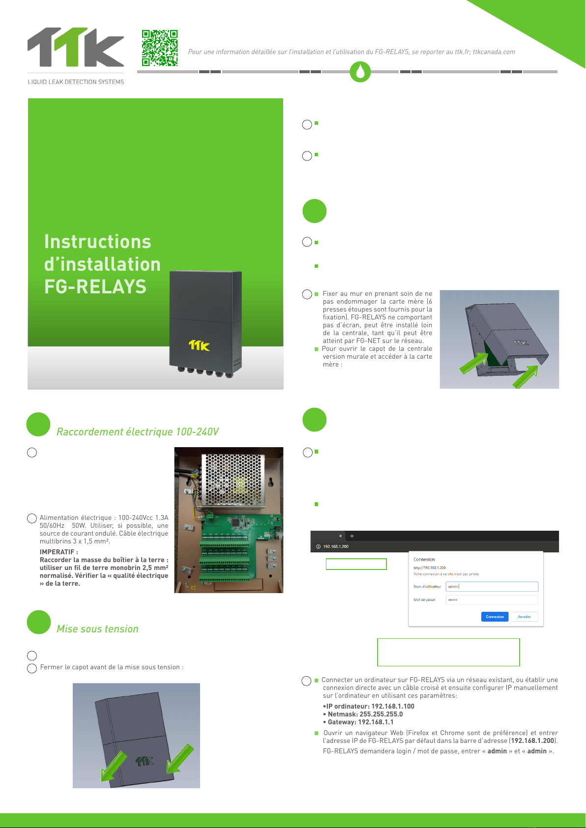
La configuration de relais externes est similaire à la configuration de relais in-
ternes de FG-NET. Sur la page d’accueil de FG-NET, dans le menu « Câbles »,
cliquer sur le bouton « Modifier » du câble détecteur que vous souhaitez configu-
rer. Une nouvelle page s’ouvre pour les configurations de relais :
Sélectionner un « Type » de la faute, fuite ou la discontinuité ;
Sélectionner l’emplacement du relais sous « Board », FG-NET ou # 1 FG-RE-
LAYS ou # 2 FG-RELAYS ...
Sélectionner un numéro de relais, 1 à 8 pour les relais locaux, et 1 à 24 pour
les relais externes ;
Appuyer sur le bouton « Ajouter » pour sauvegarder les paramètres dans la liste ;
Un réglage du relais peut être supprimé de la liste en appuyant sur l’icône de
suppression.
Relay Configurations
Tests and Simulations of Leaks
Configurations des relais
Tests et simulations de fuites
FR
FR
EN
EN
From the web interface, the IP settings can be changed according to needs;
change the box name for easier identification, and change the box password.
A table will show all 24 relays with the status for each relay.
The state of a relay can be changed by selecting the corresponding number. This
is very useful when powering up the system, or during yearly BMS testing. After
a few seconds, FG-NET will override this manual setting and reset it to automatic
mode.
Depuis l’interface Web, vous pouvez modifier les paramètres IP en fonction de
vos besoins : changer le nom du boîtier pour faciliter l’identification ou changer
le code du boîtier.
Un tableau indique les 24 relais avec leur statut.
Il est possible de changer l’état d‘un relais en sélectionnant le numéro corres-
pondant. Ceci est très utile lors de la mise en service du système ou lors de
test annuel de GTC. Après quelques secondes, FG-NET remplacera ce réglage
manuel et le remettre en mode automatique.
EN
Répéter les étapes 1 à 6 si plusieurs FG-RELAYS sont à installer.
Une fois l’installation terminée, effectuer le test sur le système FG-NET.
Contrôler le fonctionnement de l’ensemble du système : la communication
entre FG-NET et FG-RELAYS et la communication entre FG-NET et tous les
câbles détecteurs.
Vérifier la configuration des câbles et des relais.
FR
Installation Notice_FG-RELAYS_EN_FR_v1_052021
Cable name - can be
customized /
Nom du cable
- peut être personalisé
Panel name
/Nom de
la centrale:
FG-NET
Circuit #
/ N° du
circuit:
Circuit #1
Cable #
/ N° du
câble:
Cable #02
[
Location of cable / L’emplacement du câble
]
Change the IP setting according to site
needs, either manual or automatic (DHCP).
Change the IP setting according to site
needs, either manual or automatic
(DHCP).
5
A link must be created between FG-NET and FG-RELAYS. Go to the FG-NET “Se-
tup” menu, then under the “FG-RELAYS” tab, select one available field and enter
the FG-RELAYS IP or Mac address and password. Press the “enable” button, the
FG-RELAYS name will appear and the status will change to “online”.
Pairing with FG-NET
Raccordement avec FG-NET
EN
Un lien doit être créé entre FG-NET et FG-RELAYS. Dans le menu « Configura-
tion » de FG-NET, sous l’onglet « FG-RELAYS », sélectionner un champ dispo-
nible et entrer l’adresse IP ou l’adresse Mac de FG-RELAYS et le code. Appuyer
sur le bouton « enable », le nom du FG-RELAYS apparaîtra et son état passera
à « en ligne ».
FR