UFR1001E 12420-0701-08 Page 2 / 45 www.ziehl.de
1. Application and brief description .............................................................................................. 4
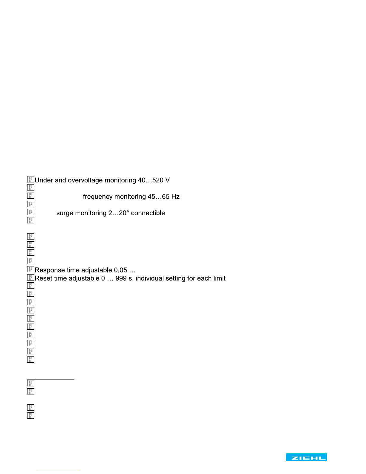
2. Summary of the functions ......................................................................................................... 4
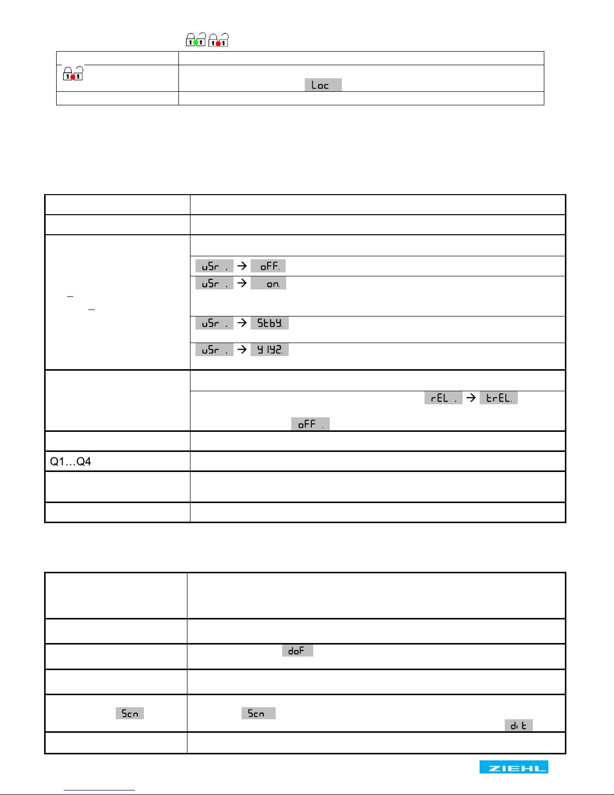
3. Display and controls .................................................................................................................. 5
4. Detailed description ................................................................................................................... 6
4.1 Description of the connections ........................................................................................... 6
4.2 Functional characteristics .................................................................................................. 6
5. Important information ................................................................................................................ 7
6. Assembly .................................................................................................................................... 8
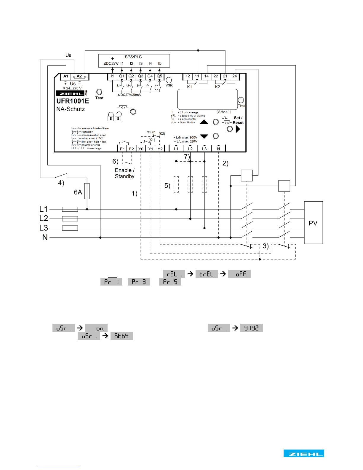
7. Connection diagrams ................................................................................................................. 9
7.1 1x
PV, 2x section switch (= Standard low voltage) ............................................................ 9
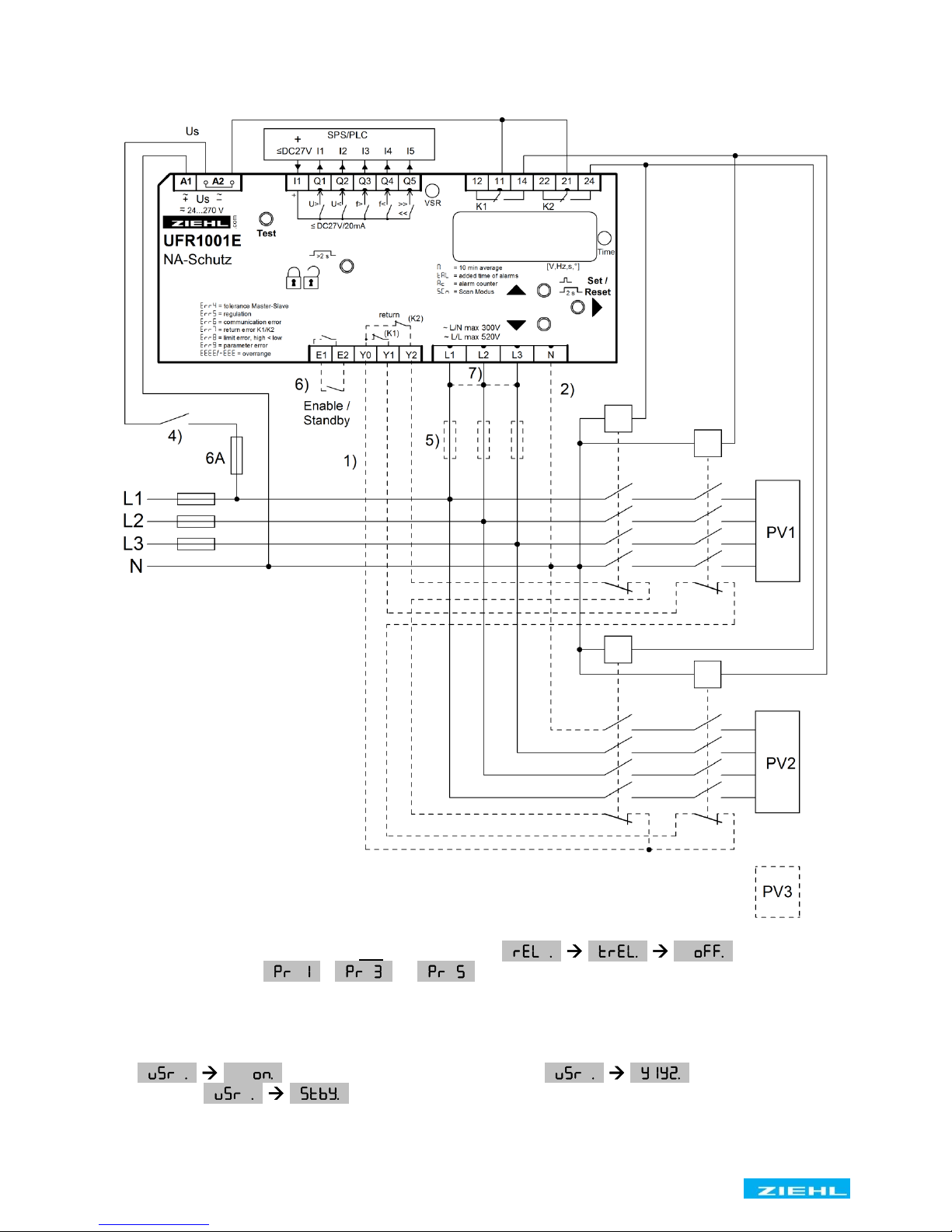
7.2 Multiple PV with section switch and with a series-switched NC's as feedback contacts .. 10
7.3 Multiple PV with section switch and with a parallel-switched closing contacts as feedback11
7.4 1x PV, 1x section switch with nc/normally closed contacts (medium voltage) ................. 12
7.5
Generator operation, suppression of the feedback contacts ............................................ 13
8. Commissioning......................................................................................................................... 14
8.1 Program setup ................................................................................................................. 14
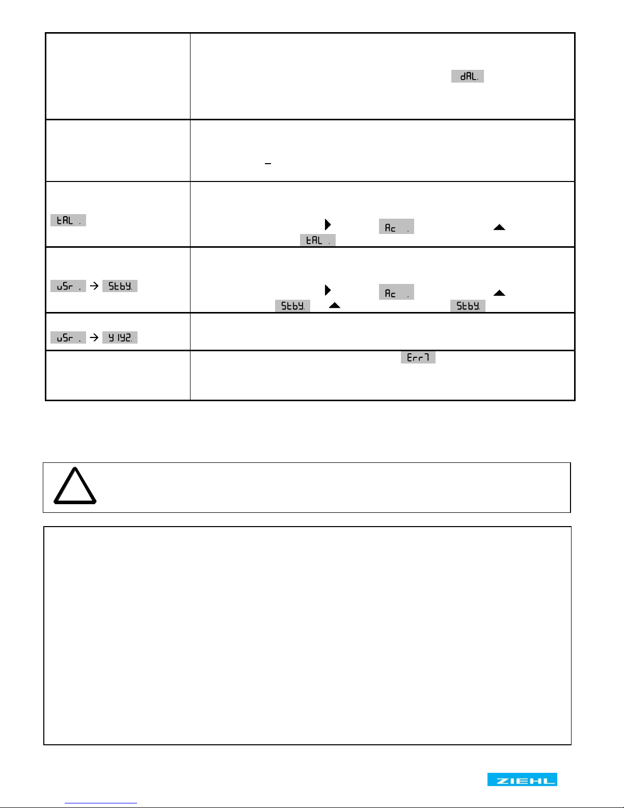
8.2 Control chart ..................................................................................................................... 15
8.3 Description of the parameters .......................................................................................... 1 7
8.4 Display mode (last decimal point off) ............................................................................... 17
8.5 Menu mode (last decimal point on) .................................................................................. 18
8.6 Configuration mode (last decimal point flashes) .............................................................. 18
8.7 Test mode (only activated and connected feedback contacts) ........................................ 18
8.8 Alarm counter................................................................................................................... 18
8.9 Cumulative alarm time (display in hours) ......................................................................... 18
8.10 Alarm memory .................................................................................................................. 19
8.11 Standby counter and standby time ................................................................................... 19
8.12 Code lock ......................................................................................................................... 20
8.13 Sealing ............................................................................................................................. 20
8.14 Simulation ........................................................................................................................ 21
8.15 Possible indications in display.......................................................................................... 22
9. Default settings and firmware version, VDE-AR-N 4105
+ BDEW ........................................ 23
9.1 Default settings and firmware version, ÖVE/ÖNORM E 8001-4-712, G83/2+G59/3 .............. 25
10. Technical Data .......................................................................................................................... 27
11. Maintenance and repair ........................................................................................................... 28
12. Troubleshooting and measures .............................................................................................. 29
13. Construction form V6 ............................................................................................................... 30
14. Certificate of conformity VDE-AR-N 4105 ............................................................................... 31
15. Certificate of conformity bdew 2008 + 2013 ........................................................................... 33
16. Certificate of conformity ÖVE/ÖNORM E 8001-4-712, Pr 10 .................................................. 40
17. Certificate of conformity GB G59/3, Pr 20+21......................................................................... 41
18. Certificate of conformity GB G83/2, Pr 22+23 ........................................................................ 42