TTM NoXygen C625 User manual

2022-09
TTM NoXygen®C625
INSTALLATION, OPERATING AND MAINTENANCE INSTRUCTIONS
Degasser

2022-09
2 (12)
TTM Energiprodukter AB
Slöjdaregatan 1 | 393 66 Kalmar | Sweden | Tel. + 46 480-41 77 40 | [email protected] | www.ttmenergi.se
For latest updates visit www.ttmenergi.se
Upon delivery
Instructions: Immediately upon receiving, check to ensure that
the delivery is complete and that nothing is damaged.
Report any transport damage immediately.
A. Main line
B. Inlet with shut-off valve
C. Treatment chamber
D. Return with shut-off valve
B
C
D
A
Principle of Operation
Table of Content
General
Principle of Operation................................................... 2
Technical Data.............................................................. 2
General Safety Instructions .......................................... 3
Installation ................................................................. 4
Pipe connection .......................................................... 4
Electrical Connection .................................................. 4
Commissioning and Operation ........................... 5
Display ....................................................................... 6
Use of Display Buttons................................................. 6
Factory Reset ............................................................... 6
Operating Modes .................................................... 6
Options ...................................................................... 7
Maintenance.............................................................. 8
Functional Control....................................................10
Troubleshooting........................................................11
Technical data
Art.no .................................................... 515180
System pressureat the connection point,
max.:.....................................................+0,8 – +2,5 bar
Allowable operational temperature:........0 – +60 °C
Ambient temperature: 0 – +40 °C
Allowable fluids: Water and deionised water
Ethanol* less than 30 vol%
Kilfrost max 30 vol%
Pressure classification: ..........................PN10
Capacity, degassed fluid:.......................min. 100 l/h
Connection dimension:..........................DN15
Electrical data:.......................................1~230 V, 50 Hz, plug
External fuse: ........................................10 A
Nominal power: .....................................0,5 kW
Nominal current: ....................................3 A
Protective class: ....................................IP44
Energy usage: .......................................25 kWh/year *
Alarm output, max load: ........................24 V, 1,0 A
Sound level:...........................................58 dB
Weight:..................................................19 kg
*) Operation with 30 days of fast degassing gives a
energy consumption of 80 kWh in the first year.
TTM NoXygen®is environmentally assessed.
Width: 540 mm
Height: 560 mm
Depth: 190 mm
540
190
500
560
370
45
250
1/2” inv. gänga
360 (upphängning) 90
12
int. thread
(Wall mount)
TTM NoXygen® C625
Installation, operating and maintenance instructions
2 (9)

2022-09
3 (12)
TTM Energiprodukter AB
Slöjdaregatan 1 | 393 66 Kalmar | Sweden | Tel. + 46 480-41 77 40 | [email protected] | www.ttmenergi.se
For latest updates visit www.ttmenergi.se
General safety instructions
TTM NoXygen®C625 is designed for stationary operation; it
is not meant for mobile system operation. The stipulated war-
ranty period applies only to a maximum of 10,000 degassing
intervals per year.
Installation must be done in accordance with national regula-
tions. Installation must be done by professionals and specially
trained staff. Information on the manufacturer, year of manu-
facture, serial number and technical data can be read on the
data plate affixed to the TTM NoXygen®C625 unit.
Take measures for temperature and pressure fusing in the
system so that the stated, allowable maximum and minimum
operating parameters are not exceeded or undercut, respec-
tively. TTM NoXygen®C625 must only be used in systems for
containing allowable fluids.
Systems using expansion vessels and pressurised expansion vessels
When operating TTM NoXygen®C625, there must be 3 litres of free expansion volume in the system.
Without this, the pressure in the system will increase and the system safety valve may release fluid in order
to reduce the pressure. If this occurs, the system’s expansion vessel like has the wrong input pressure or
there is too little room for expansion and it needs to be replaced with a larger expansion vessel.
Rule of thumb: The input pressure must be 70% of the system pressure.
NOTE: The pressure at the safety valve opening should be 30% above the system pressure.
Systems using pressure maintenance systems with compressors or pumps
Systems with pressure maintenance vessels/compressor vessels for expansion can begin to work intermit-
tently with the degasser, i.e., the expansion vessel empties and fills according to TTM NoXygen®C625's
oprertation cycles. A surge vessel measuring 50 litres should be installed in connection with the pump expan-
sion. (See the image below). The reason why this happens is that the nominal value between the opening and
the magnetic valve and the pump switch is too narrow.Then check the system pressure and system height so
that the correct system pressure is set and then give the nominal value a larger pan.
System pressure and filling of system fluid
As gasses are removed from the system fluid, the
fluid decreases in volume and the pressure within the
system is reduced. Therefore it is important to moni-
tor the system pressure and to add more system fluid
when necessary. A high gas content and continuous
operation of TTM NoXygen®can result in the system pressure falling very quickly.
An initial inspection is therefore recommended after only 24 hours of operation
System pressure
System pressure = system height (m) + 5 m.
Example
System height = 5m + 5m => 1 bar of system pressure
• Before maintenance work, the plug must be disconnected from the wall socket.
• Installation, maintenance and troubleshooting should only be carried out by
qualified personnel.
• The TTM NoXygen is usually maintenance-free but an annual function check
is recommended to ensure maintained performance, see function check page 10.
• Checking and cleaning of pre-filters should be done in conjunction with the
function check.
• In dirty systems cleaning of pre-filters needs to be done more frequently,
see page 8 and 9.
IMPORTANT!
TTM NoXygen® C625
Installation, operating and maintenance instructions
3 (9)

2022-09
4 (12)
TTM Energiprodukter AB
Slöjdaregatan 1 | 393 66 Kalmar | Sweden | Tel. + 46 480-41 77 40 | [email protected] | www.ttmenergi.se
For latest updates visit www.ttmenergi.se
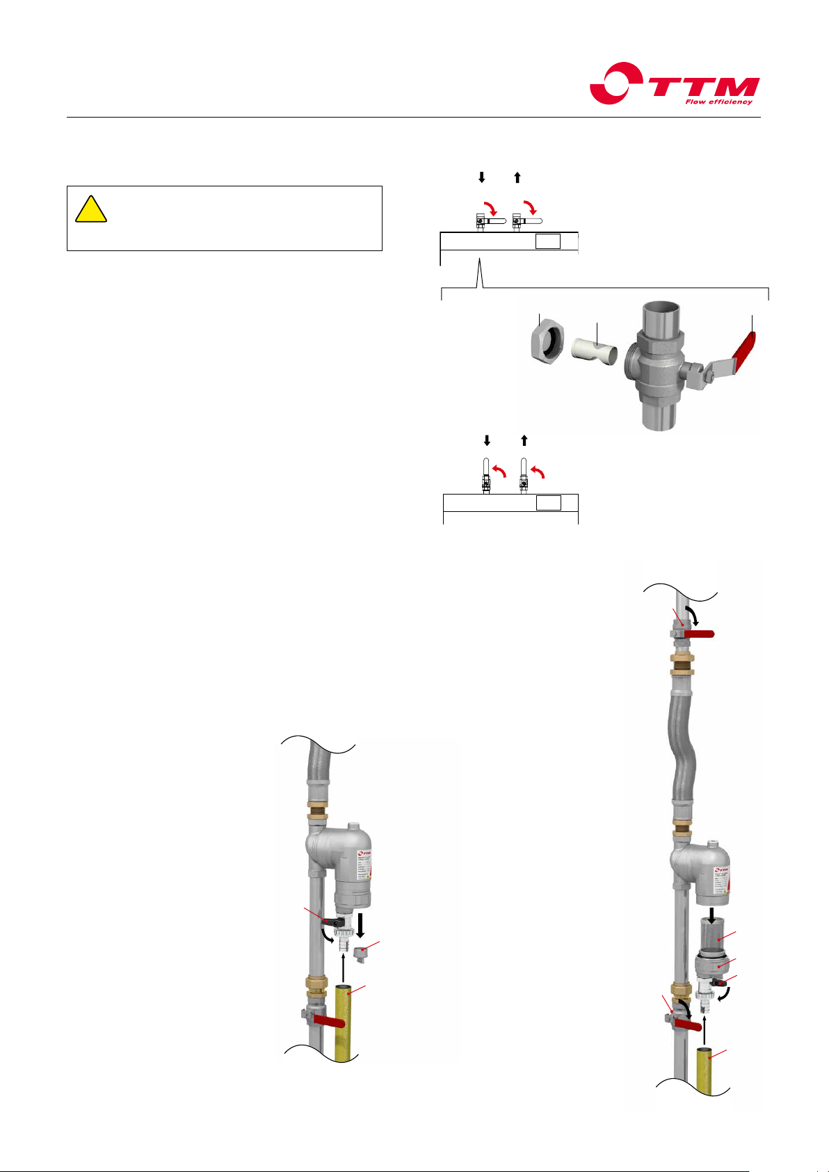
Installation
Pipe connection
• TTM NoXygen®is fitted with a ½” internally threaded connection.
The connection is made with a steel-braided hose to system’s return
conduit in front of the pump and exchanger.
• Connection to the system must always be made to the upper side
of the pipe unless a TTM MAG 54 or 76 filter is installed in front of
NoXygen on the incoming conduit.
• The distance between connection points shall be at least 300 mm
(Fig. 1 och 2).
Drip Tray
The drip tray’s ½” connection is connected to the floor drain (Fig. 3).
Mounting
For floor mounting, the TTM NoXygen®is placed on its feet so that it is
horizontal.
For wall mounting, hang the TTM NoXygen®in the unit's wall brackets so
that it hangs horizontally (Fig. 4 and dimensional drawing page 2).
Electrical Connection
TTM NoXygen®is connected by plugging in the wall plug to an earthed
socket 1-230 V, 50 Hz Alternatively, it can be connected to a fixed
earthed connection with a circuit breaker. The electrical unit should be
equipped with a residual current device.
Connection to External Monitoring (DUC)
The TTM NoXygen®is equipped with a built-in potential-free changeover
contact for buzzer alarm (Fig. 5). The switching pin is mounted externally
on the right side of the TTM NoXygen®and the alarm connector is plugged
into outputs Aand Cfor NC (Normally Closed during operation) and into
Band Cfor NO (Normally Open during operation). Operation indication is
given when the TTM NoXygen®is in operation mode (green light is on) on
the control panel.
Fig. 2.
Fig. 1
Fig. 3
Fig. 5
TTM
NoXygen®
A (NC) Normal operation
B (NO) Powerless / On alarm
C (Common)
A
B
C
Coupling pin at
normal operation
OBS!
Existing cables in the coupling slot
should not be moved or
disconnected. NC: A + C (normally closed) during operation
NO: B + C (normally open) in operation
Fig. 4
360 mm C/C
Drill hole
Ø12x80mm
Wall plug
12x60mm
French wood screw
galvanized 8x70mm
Main flow V
Circulation water
≥300
High gas
Low gas
High gas
Low gas
Main flow V
Circulation water
Main flow V
Circulation water
≥300
High gas
Low gas
High gas
Low gas
Main flow V
Circulation water
TTM NoXygen® C625
Installation, operating and maintenance instructions
4 (9)
2022-09
5 (12)
TTM Energiprodukter AB
Slöjdaregatan 1 | 393 66 Kalmar | Sweden | Tel. + 46 480-41 77 40 | [email protected] | www.ttmenergi.se
For latest updates visit www.ttmenergi.se
Commissioning and operation
1. Starting TTM NoXygen®
Press
MOVEO
twice to start the TTM NoXygen. When the green LED lights up, the unit is now in operation.
2.2 Press
MOVEO
to check date
settings "hh-mm-ss".
2.3 Press
MOVEO
to check start
time for maintenance
degassing "Tstart".
2.4 Press
MOVEO
to check the
number of hours the degasser
should be active during main-
tenance degassing, "Toperat".
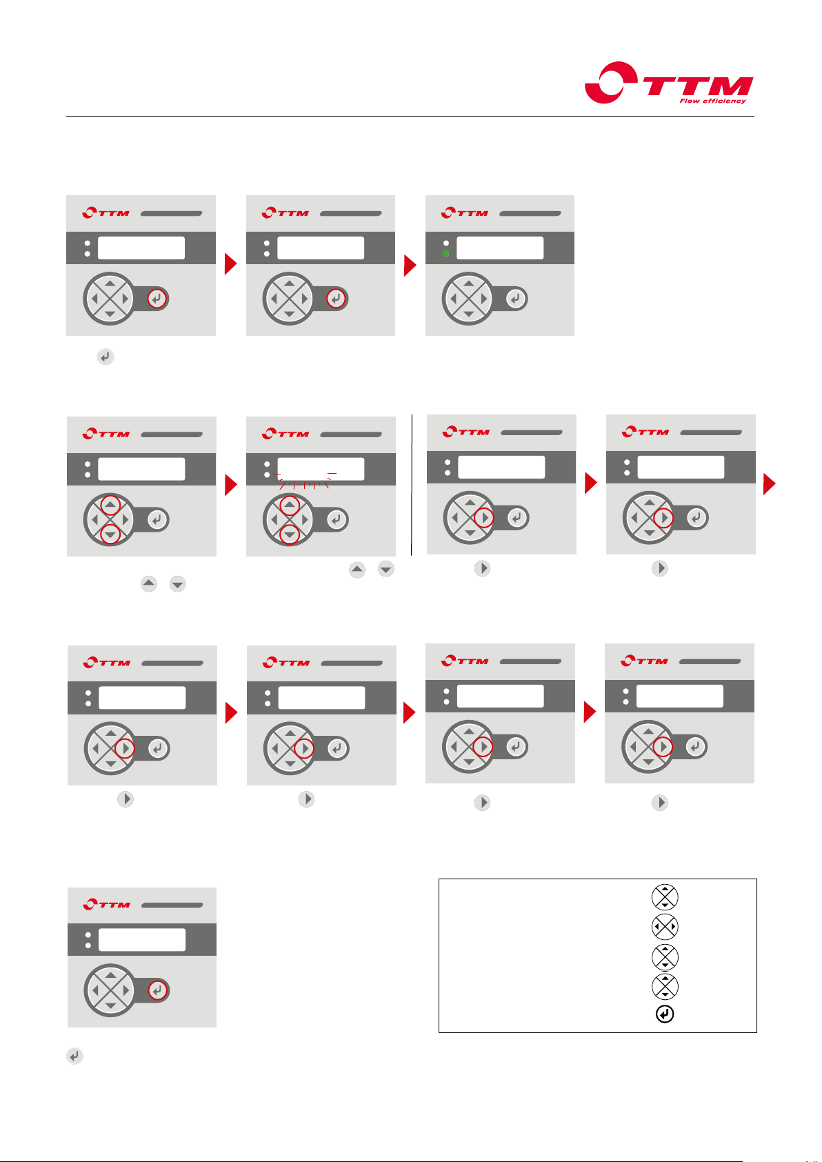
2. Kontroll och ändring av driftinställningar
MOVEOMOVEOMOVEO
Start?
T Pint 1,2
0
T Pint 1,2
0
MOVEOMOVEO
MOVEO
PROGV 2.16
hh-mm-ss
MOVEOMOVEO
MOVEO
Progv 2.16
yy-mm-dd
Progv 2.16
yy-mm-dd
Settings
To change settings, press
simultaneously
MOVEO
+
MOVEO
(up arrow
and down arrow), to get to the
change mode ("Settings" is
displayed on the display).
Simultaneously press
MOVEO
+
MOVEO
once more to change values
(settings start flashing).
Confirm and save the setting with
MOVEO
. For further instructions, see page 6.
MOVEO
Progv 2.16
Tmanoperat 30d
2.1 Press
MOVEO
to check date
settings "yy-mm-dd".
MOVEOMOVEO
2.6 Press
MOVEO
to check how long
the TTM NoXygen will run in fast
degassing mode "Days left".
2.5 Press
MOVEO
to select how long
the TTM NoXygen will run in fast
degassing mode "Tmanoperat".
3. Spara inställningar
Progv 2.16
Tstart 13:00
Progv 2.16
Topreat 1
Progv 2.16
Tmanoperat 30d
Progv 2.16
Days left 30
Progv 2.16
yy-mm-dd
TTM NoXygen® C625
Installation, operating and maintenance instructions
5 (9)
1. Menu for setting of nominal value:
2. Search value to be changed:
3. Menu for changing of nominal value:
4. Set the new nominal value:
5. Lock nominal value:
Up or down
2X to get to the
main menu
Up/down
simultaneously
Up/down
simultaneously

2022-09
6 (12)
TTM Energiprodukter AB
Slöjdaregatan 1 | 393 66 Kalmar | Sweden | Tel. + 46 480-41 77 40 | [email protected] | www.ttmenergi.se
For latest updates visit www.ttmenergi.se
Display
MOVEO
TTM NoXygen®
PROGRV 2.16
Use of display buttons
The ENTER button is used in order to:
- start and stop TTM NoXygen®("Start?" or "Stop?"
is shown on the display).
- confirm the set nominal value (setting of the nominal value,
see under the arrows below).
- go back to starting page on the display. If "Start?" or
"Stop?" can be seen on the display when returning to
the menu, press on an arrow button.
ARROWS
- the up and down arrows are pushed simultaneously in
order to get to the menu for setting the nominal value
(Settings on the display).
- Press the right or left arrow until the value to be modified
is shown on the display.
- Press the up and down arrows simultaneously again and
adjust the nominal values with the up or down arrow
(the value to modify blinks on the display).
- Confirm with ENTER.
Factory Reset:
• Unplug the unit. When in a non-powered state, press
the left and down arrows simultaneously as you
reconnect the plug.
• Hold until “OFF NOW” is shown on the display.
• Release the arrows and unplug the unit again.
• Reconnect NoXygen with the contact.
• NoXygen is now factory reset.
Operating modes
Fast degassing/Intensive degassing
For new installations and system fluid replacement, fast
degassing is recommended. Fast degassing means that the
TTM NoXygen®runs continuously between 00:00 on Monday
and 23:59 on Friday.
The preset value is 30 days of fast degassing, which in most
cases is sufficient to degass the system. In large systems or in
systems with many air pockets, longer time may be needed to
remove all air. It is possible to increase the number of days in
fast degassing mode up to 90 days.
Explanation of display messages:
Pint Displays the current pressure inside the vacuum
chamber of the NoXygen®.
Date Setting the date "yy-mm-dd".
Clock Setting of the clock "hh-mm-ss".
Tstart The time when TTM NoXygen®shall start in
timer operation.
Toperat How many hours the TTM NoXygen®shall run in
maintenance degassing per day.
Tmanoperat How many days TTM NoXygen®should be
degassed per month.
Days left How many days of fast degassing mode
remains before the TTM NoXygen®enters the
maintenance degassing.
Maintenance degassing
When the system is degassed, there is very little air left in the
system and it only costs money to keep the degasser active
around the clock and increases wear on the unit.
There is always some air leakage into the system that needs
to be taken care of. During maintenance degassing, the TTM
NoXygen®only runs for a few hours per day, which is sufficient
to take care of the system air leakage. The number of hours
per day needed to maintain low gas levels is shown in the table
below.
Recommended operating time per day
System volume Operating time
5 000 litres 1 hour
10 000 litres 2 hours
15 000 litres 3 hours
20 000 litres 4 hours
25 000 litres 5 hours
Red LED indicates
alarm.
Green LED indicates
that the unit is in
operation.
Enter
Arrows right/left,
up/down.
TTM NoXygen® C625
Installation, operating and maintenance instructions
6 (9)

2022-09
7 (12)
TTM Energiprodukter AB
Slöjdaregatan 1 | 393 66 Kalmar | Sweden | Tel. + 46 480-41 77 40 | [email protected] | www.ttmenergi.se
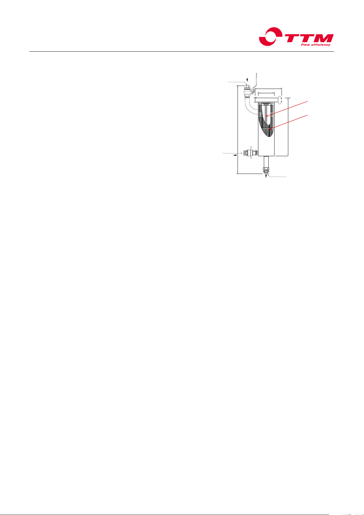
For latest updates visit www.ttmenergi.se
261
Ø75
Ø140
410
DN15 (1/2”)
DN15 (1/2”)
DN15 (1/2”)
IN
Avtappning
UT
When the gas level in a system fluid is lowered, magnetite and other sediments are often
released from the inner walls of the system. These cause wear and tear on pumps and pipe
walls, among other things, and can also cause clogging of the system. TTM MAG 76 and
TTM MAG 54 effectively remove magnetite and other particles from the system fluid, which
means:
• Fewer operating interruptions. Magnetite clogs valves and other
devices and can also make wet pumps to stick together when they are shut off.
• Longer system lifetime. Magnetite and other particles have a grinding effect that
wears away at the system. The magnetite is magnetic and is attracted to the magnetic
field in pumps, where it wears away at axle seals, for example, which often results in
leakage.
• Protects the degasser. I system med hög förekomst av partiklar förhindrar TTM MAG
54/76 att avgasningsprocessen försämras på grund av igensättning av avgasaren.
The recommendation is to install TTM MAG 76 or TTM MAG 54 along with TTM NoXygen®.
It is especially important to install Mag 76 when it is known that magnetite or other particles
in the system fluid.
Installation
When installed in combination with the TTM NoXygen®degasser, the TTM MAG 54/76 is
connected to the system (½" female pipe thread) and then mounted directly on the shut-off
valve on the inlet of the TTM NoXygen®. When connecting to the TTM NoXygen®, first fit the
supplied clamping ring coupling, then connect the flat end of the TTM MAG 54/76 to the
clamping ring coupling.
TTM Offset is a Equalisation vessel used together with the TTM
NoXygen®in heating/cooling and recycling systems that are sensitive to
pressure variations e.g. pump expansion systems.
TTM Offset counters the pump expansion system turning on and
creating noise in the property’s system. It can also contribute to longer
durability in pump expansion systems, as the shutdowns do not occur
as often.
The TTM Offset is equipped with a control valve that is used as a
shut-off or drain valve when checking and adjusting the pressure
in the leveling vessel.
Installation
1. Close the shut-off valve to the system.
2. Remove the protective cover on the drain valve.
3. Open the drain valve (the spindle located on the side) and let the
water drain out.
4. Remove the black protective cover and take off the valve cap to
air valve.
5. Adjust the rubber lock pre-pressure so that this corresponds to
70-80% of the system pressure by releasing or replenishing air
through the air nipple.
6. Close the drain valve and reinstall the valve bonnet and
protective cover.
7. Reassemble the protective cover to the drain valve.
8. Open the shut-off valve to the system.
TTM MAG 54 och TTM MAG 76
TTM Offset 510 Art.no: 506430
TTM NoXygen®
Degasser
TTM MAG 54
Magnetite filter
Main pump
TTM Flexible
hose
TTM Offset
Equalisation
vessel
Return flow
TTM GeniX®
Pressurization unit
Art.no: 506188Art. no: 514428
100 57
190
255
Utv.
DN15 (1/2”)
UT
Inv.
DN15 (1/2”)
Ø15 mm
slang-
anslutning
TTM MAG 76
TTM NoXygen® C625
Installation, operating and maintenance instructions
7 (9)
Options Female
Male
OUT
Hose
connection
Drain
OUT
2022-09
8 (12)
TTM Energiprodukter AB
Slöjdaregatan 1 | 393 66 Kalmar | Sweden | Tel. + 46 480-41 77 40 | [email protected] | www.ttmenergi.se
For latest updates visit www.ttmenergi.se
Mounting the strainer basket
5. Replace the strainer basket Cin the inlet valve. Ensure that the filter
basket is entirely submerged and sits evenly with the valve body.
6. Make sure that the protective cap gasket is correctly located. Screw
the protective cap Bon the inlet valve with a spanner.
7. Turn the inlet and outlet valve handle A to the open position.
Disassembly of the inlet valve
3. Loosen the protective cap Bon the inlet valve with a spanner.
Let the gasket remain in the protective cover.
4. Remove the filter basket Cand clean it and the protective
cap with water.
Before starting cleaning of the inlet valve, ensure that:
1. The inlet and outlet valve handle A is in the closed position.
2. The TTM NoXygen® is turned off or the the main power is isolated. A
B
C
Inlopp Utlopp
Cleaning the filter basket of the inlet valve
Maintenance
Maintenance of TTM MAG 54
A
A
Inlopp Utlopp
!WARNING
If TTM NoXygen®is installed in a heating system then hot
pressurised system fluid may leak out when the protec-
tive cap B is unscrewed.
A
A
Inlet
Inlet
Outlet
Outlet
Cleaning the particle filter
1. Switch off both TTM NoXygen®and the main
power.
2. Close both inlet valves 1.
3. Install hose 6on the hose connector.
4. Empty the magnetite filter by opening the
drain valve 3. Leave the water to run until the
housing is empty of water.
5. Unscrew the bottom insert 4.
6. Unscrew the magnet insert 2 (see image 1).
7. Clean the particle filter 5and other parts
with lukewarm water.
8. Screw the magnet insert back in place 2.
9. Ensure the particle filter 5 and the O-ring
are correctly installed and screw the bottom
insert 4into the housing.
10. Close the drain valve 3.
11. Open both inlet valves 1.
12. Start TTM NoXygen®.
Cleaning the magnetite trap
1. Switch off both TTM NoXygen®and the
main power.
2. Close both inlet valves 1
(see image 2).
3. Install hose 6on the hose connector.
3. Unscrew the magnet insert 2.
4. Empty the particle trap by opening
the drain valve 3. Leave the water to run
until the housing is empty or until the fluid
is clear and without contaminants.
5. Close the drain valve 3and screw the
magnet insert back in place 2.
6. Open both inlet valves 1
(see image 2).
7. Start TTM NoXygen®.
(Image 1)
TTM MAG 54 should be inspected and cleaned regularly, at least
twice per year. The intervals depend on the quantity of particles and
magnesite in the system fluid. If you know the system fluid is very dirty,
the filter should be inspected and cleaned more often. One sign that
TTM MAG 54 requires cleaning is, for example, that TTM NoXygen®
runs for long intervals exceeding 3 minutes “pump start to pump start”
(see Operating and maintenance instructions for TTM NoXygen®).
(Image 2)
2
4
5
1
6
1
3
6
3
TTM NoXygen® C625
Installation, operating and maintenance instructions
8 (9)
2022-09
9 (12)
TTM Energiprodukter AB
Slöjdaregatan 1 | 393 66 Kalmar | Sweden | Tel. + 46 480-41 77 40 | [email protected] | www.ttmenergi.se
For latest updates visit www.ttmenergi.se
Maintenance of TTM MAG 76
TTM MAG 76 must be checked and cleaned regularly – at least twice per
year. The interval depends on the quantity of dirt and magnetite in the
system fluid. One sign that TTM MAG 76 requires cleaning is, for example,
that TTM NoXygen®runs for long intervals exceeding 3 minutes “pump
start to pump start”.
Note: Copper paste/silicone grease must be applied to the thread of the
clamp ring once per year or every time the filter is opened.
1. Switch off TTM NoXygen®.
2. Shut off the shut off valves on the inlet to
TTM MAG 76 and the inlet to TTM NoXygen®.
3. Place a container under the drain valve or connect a hose to it.
4. Open the drain valve.
5. Undo the clamp ring and lift out the magnetic rod and filter cartridge.
6. Wipe off the black magnetite that has collected on the magnetic rod.
7. Clean the filter cartridge or replace it if it is damaged.
8. Refit the filter cartridge and magnetic rod and fix into place with the
clamp ring. Grease the clamp ring threads with copper paste/silicone
grease before tightening.
2. Replaceable filter cartridge
Article no: u2001217
1. Magnetic rod
261
Ø75
Ø140
410
DN15 (1/2”)
DN15 (1/2”)
DN15 (1/2”)
IN
Avtappning
UT
1
2
Drainage
OUT
Maintenance
TTM NoXygen® C625
Installation, operating and maintenance instructions
9 (9)
2022-09
10 (12)
TTM Energiprodukter AB
Slöjdaregatan 1 | 393 66 Kalmar | Sweden | Tel. + 46 480-41 77 40 | [email protected] | www.ttmenergi.se
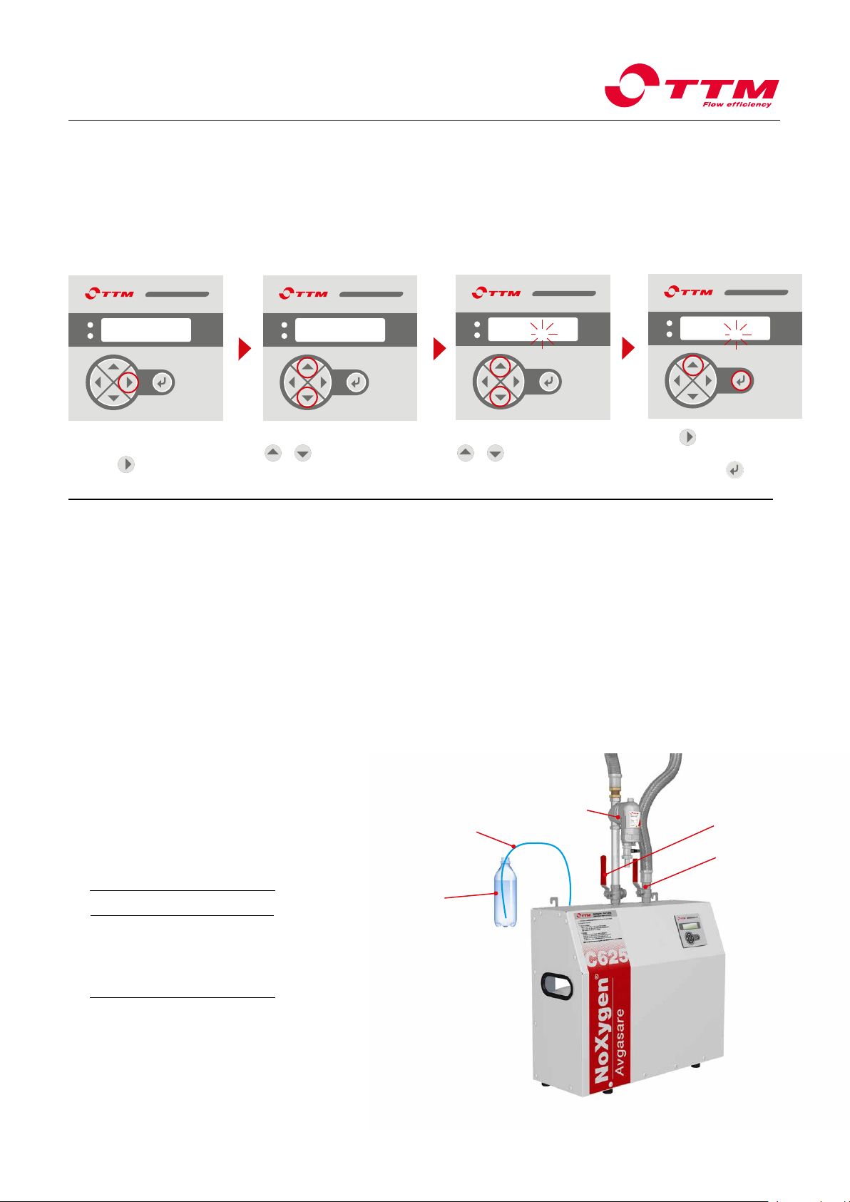
For latest updates visit www.ttmenergi.se
Before the function check, the pre-filters must be cleaned (see page 8) and the system pressure
needs to be at least 0.8 bar for the function check to be made.
MOVEO
TTM NoXygen®
Degasser
Blue
control hose
Transparent
bottle
filled with
water.
TTM MAG 54
Magnetite
separator Shut off valve
Shut off valve
1. Expansion vessel control
Check that the expansion tank is correctly adjusted with cor-
rect pre-pressure and that there is free expansion volume. The
TTM NoXygen®C625 requires at least 3 litres of free expansion
space. If it is suspected that the expansion space is too small,
install TTM Oset expansion vessel(art.no. 506430).
2. Pressure sensor control
Check that the "Pint" pressure on the TTM NoXygen®display
in idle mode is between minimum 0.8 bar and maximum 2.5
bar (the unit will not start if the pressure is below 0.8 bar, see
troubleshooting action 1.1). If the pressure on the display does
not match the system pressure, see troubleshooting action 7.
Also check that the "Pint" reaches at least -0.7 while the pump
is running. If not, see troubleshooting action 2.
3. Operating cycle time control
The time from pump start to pump start should not exceed the
recommendations in the table below. Long cycle times indicate
clogging of lters or ow restrictors.
See troubleshooting action 3.
4. Leakage control
Check that no uid is leaking from the blue control hose, when
the "Pint" pressure is equal to the system pressure of the plant,
in case of leakage, contact TTM. Check that no system uid
is leaking from any of the connections to the pump or vacuum
chamber.
5. Degassing capability control
When the TTM NoXygen® starts, close the shut-o valve on the
inlet and check that the "Pint" pressure reaches at least -0.7. If
not, see troubleshooting action 2. Allow the machine to stand
with the valves closed for at least 5 minutes and check that the
pressure does not change. If the pressure increases, there is a
leak, see troubleshooting action 5:3.
Preparation before function check - Test run settings
Functional control
Progv 2.16
Tmanoperat 0d
MOVEO
Progv 2.16
Tmanoperat 0d
Then press simultaneously
MOVEO
+
MOVEO
to activate
"Settings".
Then press simultaneously
MOVEO
+
MOVEO
to activate
editing mode.
Press
MOVEO
to set "Tmanope-
rat = 1d". Confirm by saving
the setting with
MOVEO
.
MOVEO
Progv 2.16
Tmanoperat 1d
MOVEO
Set the TTM NoXygen® to
continuous operation by
pressing
MOVEO
until
"Tmanoperat"appears on the display.
Settings
Set the TTM NoXygen®to continuous operation by adjusting "Tmanoperat" to 1day
TTM NoXygen® C625
Installation, operating and maintenance instructions
10 (9)
Pressure Time
1,0 bar 95 seconds
1,5 bar 90 seconds
2.0 bar 85 seconds
2,5 bar 80 seconds

2022-09
11 (12)
TTM Energiprodukter AB
Slöjdaregatan 1 | 393 66 Kalmar | Sweden | Tel. + 46 480-41 77 40 | [email protected] | www.ttmenergi.se
For latest updates visit www.ttmenergi.se
Solution
Raise the system pressure to at least 0.8 bar.
Check that there is voltage to the TTM NoXygen®.
Check that the TTM NoXygen®is in operating mode.
Press twice, then enter.
Check and change settings if necessary.
If necessary, change start time Tstart and/or operating
time "Toperat" or change time and date settings.
Ventilate the pump. NOTE It may take up to 10 minutes
for the pump to vent itself.
Check that the shut-off valves to the system are open.
Check that nothing else is blocking the flow paths.
Close the shut-off valve on the inlet and check if negative
pressure is created. If negative pressure is created,
check that there is a flow restrictor in the tank by loose-
ning the hose connection at the tank and removing the
insert. There should be three sleeves in the insert.
Clean any pre-filters and the strainer on the inlet
valve. If necessary, check the flow restrictors according
to 2.3.
Increase the set point between the solenoid valve and
the pump.
Install the Offset Equalizing vessel at the pressure
maintenance vessel, see instructions on page 2.
Install a new safety valve.
TTM NoXygen®requires 3 litres of free expansion space.
Install a TTM Offset Equalizing Vessel at the pressure
holding vessel, see instructions on page 2.
Check oxygen content. At oxygen levels below 1 mg/l, it
may take several cycles before air bubbles are released
through the vent.
Contact TTM.
Connect the control hose to a bottle of water if it is not
already connected and check that water is not being
sucked from the bottle into the TTM NoXygen®. If this is
the case, contact TTM.
Check that a vacuum is building up (at least -0.8 bar).
Check that the shut-off valves of the system are open.
Clean inlet valve filters and any pre-filters, see mainte-
nance instructions.
Contact TTM.
Cause
1:1 The system pressure is lower than 0.7 bar.
1:2 The control panel is without power.
1:3 Green LED is not lit.
1:4 Date or time is incorrectly set.
1:5 TTM NoXygen®is in maintenance mode and
start and run time settings put the unit in sleep
mode.
2:1 Air in the pump.
2:2 Flow at the outlet is obstructed.
2:3 Flow restrictor on inlet misadjusted.
3:1 See recommended operation cycle times in
the table under function check on page 10.
4:1 Set point between solenoid valve and pump is
set too narrow on the pressure retaining vessel.
4:2 There is no free expansion volume in the
system.
5:1 Fault in safety valve.
5:2 There is no free expansion volume in the
system.
6:1 The system is degassed or the gas content is
low.
6:2 The deaerator is clogged with dirt and
cannot open to release air.
6:3 The check valve on the air vent is leaking.
6:4 The degassing function is not working.
7:1 Restricted or no flow through inlet.
7:2 Pressure sensor is defective.
Issue
1. TTM NoXygen®does not
start.
2. A negative pressure is not
created in the TTM NoXygen®
(at least -0.7 bar).
3. The time between degassing
cycles is too long.
4. The systems's pressure ves-
sel works intermittently with the
TTM NoXygen®.
5. The system safety valve
releases system fluid.
6. No air bubbles comes out
of the control hose (NOTE: the
control hose needs to be placed
into a bottle of water).
7. System pressure does not
match the pressure on the
display.
Troubleshooting
TTM NoXygen® C625
Installation, operating and maintenance instructions
11 (9)

© All rights reserved TTM Energy Products AB, Kalmar
We reserve the right to make design changes and for any printing and factual errors. 2022-09
TTM Energiprodukter AB
Slöjdaregatan 1 | 393 66 Kalmar, Sweden | Tel. +46 480-41 77 40 | [email protected] | www.ttmenergi.se
För senaste uppdateringar se www.ttmenergi.se
Table of contents
Other TTM Industrial Equipment manuals


Popular Industrial Equipment manuals by other brands

Maico
Maico EW-S Mounting and operating instructions

Huvema
Huvema XOTR 60 S instruction manual

Emerson
Emerson Leroy Somer DIGISTART D3 user guide

York
York AHV8 UH Series User's information, maintenance and service manual

Hofmann
Hofmann Monty 3300-24 Smart Operation manual

Nidec
Nidec Leroy-Somer TAL 044 Installation and Maintenance


