Tuff-Built Best Hoist 60138 Manual

122 Paquin Rd. Winnipeg, MB R2J 3V4
Ph: (204)222-4025, Fax (204) 222-4080, Toll Free (877) 422-6053 www.tuffbuiltproducts.com
August 31, 2020 Form: 132062 rev01
Material Winches
This manual applies to the following Pt#’s;
60138, 60521, 60523
Both “Fixed Handle”and “Power Drive” Models.
Operation &
Maintenance
Manual
Material Winch Rated for: 400 lbs (181 kgs) WLL.
One (1) Pulley reeved system; Working Load Limit of 400 lbs (181 kgs).
Two (2) Pulley reeved system; Working Load Limit of 800 lbs (363 kgs).

Best Hoist Material Winch
Operation and Maintenance Manual
2
135062 rev01, 31AUG2020
Table of Contents
1. PARTS IDENTIFICATION
2. INTRODUCTION to WINCH APPLICATIONS
3. APPLICATION RESTRICTIONS
5. WINCH INSTALLATION and OPERATION
6. POWER DRIVE APPLICATIONS
7. TRAINING / INSPECCTION
8. MAINTENANCE LUBRICATION and STORAGE
9. SPECIFICATIONS
10. RISK ASSESSEMENT
11. WINCH INSPECTION LOG
12. WINCH LINE INSPECTION LOG
13. SERVICE INTERVAL RECORD

Best Hoist Material Winch
Operation and Maintenance Manual
3
135062 rev01, 31AUG2020
1.0.PARTS IDENTIFICATION
Fig 1a, Fixed Handle Models Fig 1b, Removable Handle / Power Drive Models
Item Number
Description
1
Pinion Shaft Assembly
2
Drum Spool Assembly
3
LHS Side Plate Assembly
4
RHS Side Plate Assembly
5
Crank Handle Knob Assembly
6
Brake Wear Indicator Label
7
Brake Wear Indicator Window
8
Removable Handle / Power Drive Input Hub Ass’y
9
Rear Frame Spacer
10
Rear Frame Spacer Screw
11
Crank Handle Spring Retainer Disc
12
RHS Cover
13
RHS Cover Label
14
LHS Cover
15
Crank Handle Spring
16
Removable Handle Assembly
17
Brake Wear Indicator Window Retainer Clip
18
Crank Handle Spring Retainer Disc Mounting Screw
19
Crank Handle Knob Assembly Mounting Screw
20
Crank Handle Knob Assembly Retaining Screw
21
Long RHS Cover Mounting Screw
22
LHS Cover Mounting Screw
23
Handle Retainer Snap Ring
24
Short RHS Cover Mounting Screw
Figure 1, Winch Parts and Location
Note: For purposes of honoring warranty claims, wear to brake pads, cable retainer spring bar, labels, and winch lifelines
are considered part of normal winch operation and are not covered by the warranty.
7
11
16
8
23
4

Best Hoist Material Winch
Operation and Maintenance Manual
4
135062 rev01, 31AUG2020
2.0. INTRODUCTION to WINCH APPLICATIONS
Congratulations on your purchase of a Best Hoist Material Winch.
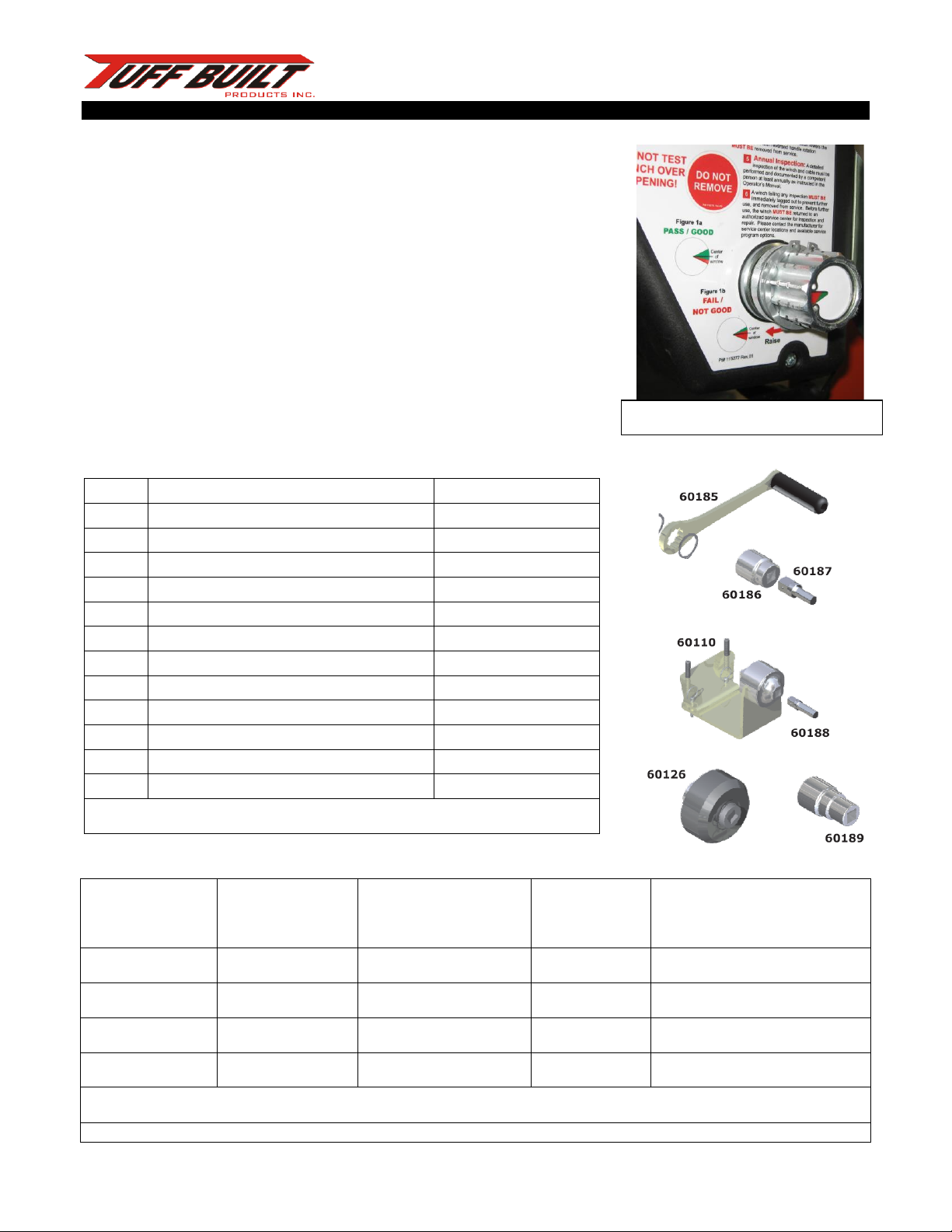
Pro-Series winches combine many advanced safety features, easy to read visual brake wear indicator, visual overload
indicator integral to the snap hook, and optional usage indicator.
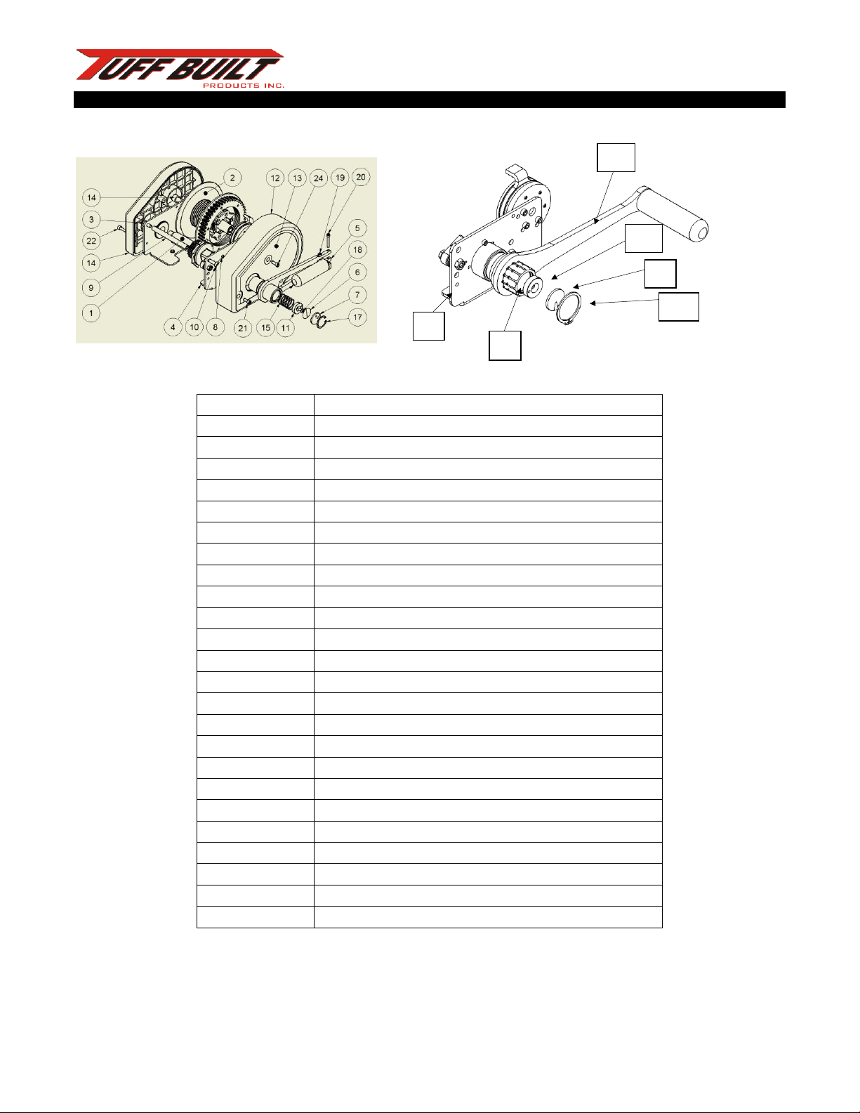
Some versions of these winches feature a unique drive input hub design which allows the winch to be easily switched from
a manual crank to various power drive options to allow the winch to be driven with different types of corded and cordless
power hand drills (See Section 6 for further information on Power Drive options).
The winch may be equipped with a variety of winch line options including, stainless or galvanized steel cable in various
diameters, and ropes in various diameters and constructions to meet your specific job requirements.
This product has been specifically designed and carefully manufactured to provide reliable operation in many different
safety-at-heights applications. These include, but are not limited to:
2.5 MATERIAL HANDLING
The winch may be used for the raising and lowering of tools, equipment, and other material not exceeding the rated
Working Load Limit of the winch. Be aware of and follow the regulations governing your workplace.
3. APPLICATION RESTRICTIONS
There are restrictions and limitations that must be carefully considered in the selection, installation, and operation of this
winch. Serious injury or death may result from failure to consider these factors.
3.1 WORKING LOAD LIMIT
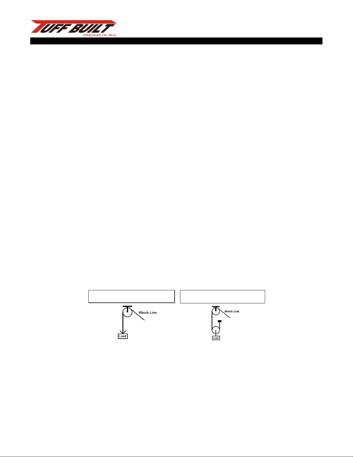
This winch is designed and rated to a working load of 400 lbs (181 kgs) when used in a 1 Pulley Single Reeved System, or a
maximum of 800 lbs (363 kgs) when used in a 2 Pulley Single Reeved System (see Figure 2).
Figure 2, 1 & 2Pulley Single Reeved Systems
Please refer to the Operator’s Manual(s) for all other accessories in the system to determine which reeving option(s) are
applicable to the system.
Note: Please be aware that a 2 Pulley Single Reeved System is rated for a higher working load limit, but that
raising/lowering speed is only half that of a 1 Pulley Single Reeved System.
Ensure that all other system components have a working load limit matching that of the winch. System rating is equal to
that of the lowest rated system component.
1 Pulley single reeved system
2 Pulley single reeved system

Best Hoist Material Winch
Operation and Maintenance Manual
5
135062 rev01, 31AUG2020
3.2 SITE CHARACTERISTICS, PHYSICAL and ENVIRONMENTAL FACTORS
Work sites have associated with them any of several hazards related to the site itself. These may include but are not
limited to poisonous or explosive atmospheric conditions, poisonous or corrosive chemical hazards, hot surfaces, electrical
hazards, sharp edges, engulfment hazards, or moving machinery.
All these factors must be taken into consideration when selecting equipment for a given application.
5. WINCH INSTALLATION and OPERATION
5.0 INTRODUCTION
This winch is designed for use in conjunction with various styles of support structures to meet different requirements.
These include tripods, davits, and pole hoists as well as a variety of special applications or custom structures. This product
is intended for use only with products designed, manufactured and/or approved by Tuff Built Products Inc. Other
applications must be designed, installed, and used under the supervision of a Qualified Person. All installations must be
approved by a Qualified Person.
5.1 WINCH INSTALLATION
This winch may be used in conjunction with a wide variety of accessory products. Please refer to the Operator’s Manual
provided with all Tuff Built Products Inc. accessories at the time of purchase for detailed information on the installation of
the winch onto the system.
For systems not supplied by Tuff Built Products Inc. the Qualified Person responsible for the design, installation, and use of
the system must provide detailed information regarding the installation of the winch onto the system.
5.2 WINCH OPERATION
Once the winch has been properly installed into the system, the operation of the winch is as outlined below. No person
shall use this winch without receiving proper training as outlined in Section 6. Any user must fully read and understand this
manual and any other instruction manual(s) related to the system being used, or have the instructions explained to them,
before using this equipment.

Best Hoist Material Winch
Operation and Maintenance Manual
6
135062 rev01, 31AUG2020
5.2.1 INSPECTION
This winch must be inspected before each use as outlined in Section 7.1.
Daily inspection instructions are also given on the label on the handle-side
cover of the winch (see Figure 4).
Any problems must be reported immediately to your supervisor, and the
equipment labeled to prevent further use until it has been repaired.
5.2.2 ATTACHING A WORKER TO THE WINCH LINE
Any worker who is connected to this winch MUST wear a full body harness
designed, tested, and approved for fall arrest. The winch line MUST be
connected to the dorsal (rear) D-Ring on the harness, unless otherwise
instructed by a qualified person.
Extend sufficient winch line to allow the line to be easily attached to the
worker’s dorsal D-Ring. Be sure to maintain sufficient tension in the line to
prevent “bird-nesting” of the winch line.
Attach the winch line to the worker’s dorsal D-Ring, making sure that the
snap hook operates smoothly and fully locks when attached.
Retract the winch line until the line is snug, and have the worker slowly lift
their feet off the ground to verify system integrity.
**DO NOT TEST SYSTEM INTEGRITY OVER AN OPENING OR WHERE
THERE IS A CHANCE OF FALLING**
5.2.3 RAISING OR LOWERING A WORKER
Equipment can be lowered by cranking the winch handle counterclockwise and raised by cranking the winch handle
clockwise. DO NOT use the winch if the rotation of the winch handle is reversed, or if the winch does not make a regular
clicking sound when cranking the winch handle in a clockwise direction.
Crank the handle at a smooth and steady pace that you find comfortable to maintain.
Wear gloves if your hands will come in contact with the winch line.
Maintain sufficient tension on the winch line, either from the weight of the equipment or manually, to ensure that the line
winds evenly onto the spool. Do not allow any slack line to accumulate between the winch and the worker if there is any
risk of a fall occurring. Serious injury or death may result if equipment is connected to a slack winch line.
Figure 4, Daily Inspection Instructions

Best Hoist Material Winch
Operation and Maintenance Manual
7
135062 rev01, 31AUG2020
6. POWER DRIVE APPLICATIONS
In applications involving repeated positioning activities or long vertical entries, it is
sometimes desirable to have a powered winch rather than relying on manual
cranking.
The winches are designed with a unique input drive hub (see Figure 5) that allows
for convenient switching between manual crank and powered operation while
maintaining a manual backup in the event of power failure or mechanical
problems.
Depending on the nature of the application, the regulations governing the use of
powered winches to raise and lower equipment in various jurisdictions, and the
type and specifications of power drills available, there are several configurations
of Power Drive accessories that may be appropriate (see Figure 6).
Figure 6, Pro-Series Winch Power Drive Accessories.
Configuration are
per figures #
Minimum Drill
Torque (FT-LB /N-m)
Maximum Drill Speed
(RPM)
for Rescue / Material
handling (310lbs/140 kgs)
Maximum Drill
Speed (RPM) for
Work Positioning
RECCOMENDED DRILL MAKE &
MODEL
Figure 8 (page 12)
40 / 54.2
300
NOT permitted
Milwaukee Hole Hawg Drill
(Model #1676-6) Corded 120V AV
Figure 9 (page 12)
10 / 13.6
600
400
Milwaukee Right Angle Drill
(Model #0721-21) Cordless 28V DC
Figure 10 (page 13)
40 / 54.2
300
Not permitted
Milwaukee Hole Hawg Drill
(Model #1676-6) Corded 120V AC
Figure 11 (page 13)
10 / 13.6
600
400
Milwaukee Right Angle Drill
(Model #0721-21) Cordless 28V DC
While Tuff Built Products recommends the above Milwaukee products, any drill meeting the same specifications of the above drills can
be used.
The use of HIGH SPEED (RPM) drills will result in damage and premature failure of winch components.
Figure 7, Drill Requirements for Various Configurations.
Part#
Description
Includes
60110
4:1 Gear Reduction
60110
60126
Overload Protection Clutch (310/620 lbs.)
60126
60186
Adapter, Crank Hub to 3/4” Drive (2.25” Long)
60186
60187
Adapter, Drill Chuck to 3/4” Drive
60187
60188
Adapter, Drill Chuck to 1/2” Drive
60188
60189
Adapter, Crank Hub to 3/4" Drive (3.50” long)
60189
60248
Pro-Series Winch Crank Handle (Removable)
Handle & Snap Ring
60193
Kit, Direct Drive
60186 w/ 60187
60194
Kit, Direct Drive w/ Overload Clutch
60126 w/ 60187
60195
Kit, 4:1 Gear Reduction w/ Overload Clutch
60126, 60110 w/ 60188
60196
Kit, Direct Drive
60189 w/ 60187
60197
Kit, Direct Drive w/ 4:1 Gear Reduction
60189, 60110 w/ 60188
Combine these accessories as shown in Figures 7-10 to make the configuration best
suited to your application.
Figure 5, Winch Input Drive Hub

Best Hoist Material Winch
Operation and Maintenance Manual
8
135062 rev01, 31AUG2020
Figure 8 below shows the simplest option of directly driving the input hub using a solid drive shaft and a low speed high
torque drill.
Rescue and Material Handling 400 lbs (181 kgs).
Figure 8, Direct Drive Configuration –1:1 application (Pt# 60193 kit)
Figure 9 shows a direct drive configuration using the 4:1 gear reduction to allow use of a higher speed, lower torque drill if
desired.
Rescue, Material Handling 400 lbs (181 kgs).Work Positioning.
Figure 9, Direct Drive Configuration –using a 4:1 gear reduction assembly (Pt# 60197 kit)
These direct drive configurations are NOT SUITABLE for personnel handling applications and is
intended ONLY FOR MATERAIL HANDLING or cable spooling operations.
The Direct Drive configurations are ONLY for rescue or material use. It is not recommended for work
positioning or continuous use. Extended use of the Direct Drive configuration will decrease the life
expectancy of the winch.

Best Hoist Material Winch
Operation and Maintenance Manual
9
135062 rev01, 31AUG2020
Figure 10 shows the most basic configuration driving the input hub
straight from the drill through an overload clutch designed to slip.
Rescue and Material Handling 400 lbs (181 kgs).
Figure 11 shows the combination of the 4:1 gear reduction drive
with the overload clutch to allow Work Positioning using a
higher speed, lower torque drill if desired.
Rescue, Material Handling 400 lbs (181 kgs),
Work Positioning.
7.TRAINING
Users must fully read and understand this manual and any other instruction manual(s) related to the system being used, or
have the instructions explained to them, before using this equipment.
7.INSPECTION
7.1 DAILY INSPECTION
The winch must be inspected before each use as described in Sections 7.1.1 to 7.1.5. Report any problems or concerns to
your supervisor, and do not use the equipment until they have approved doing so.
7.1.1 Cleaning and Lubrication
If required, clean and lubricate the winch and all its parts as outlined in Section 8. Do not use solvents or other chemicals to
clean the winch.
Figure 10, 1:1 Direct Drive with Overload Clutch
(Pt# 60194 kit).
Figure 11, 4:1 Reduction Drive with Overload Clutch
(Pt# 60195 Kit).

Best Hoist Material Winch
Operation and Maintenance Manual
10
135062 rev01, 31AUG2020
7.1.2 Physical Damage
Inspect the winch, winch line, snap hook, and mounting brackets for physical damage; bent parts, cracked housings, dented
covers, loose or missing hardware or parts, missing, or illegible labels (see Figure 5). Replacement labels are available from
your dealer by ordering the part number shown on each label.
Note: Not all labels shown may be present on your winch, as some are related to standards and certifications that may not
apply to your jurisdiction.
Figure 5, Winch Labels
While minor cosmetic damage will not impair the function of the winch, a seriously damaged winch MUST BE removed from
service and returned to an authorized service center for repair prior to further use.

Best Hoist Material Winch
Operation and Maintenance Manual
11
135062 rev01, 31AUG2020
7.1.4 Brake Wear Indicator Reading
Inspect the brake wear indicator as shown in Figure 7.
With a minimum 33lbs (15kg) tension on the cable,
check the position of the red/green indicator label
visible through the cutout in the center of the handle.
A winch with an indicator showing 50% or more red
MUST BE removed from service and returned to an
authorized service center for repair prior to further
use.
7.1.5 Crank Handle Rotation Direction and Ratchet Operation
Check the direction of crank handle rotation to verify that the
winch line is extended by cranking the winch handle
counterclockwise and retracted by cranking the winch handle
clockwise (see Figure 7). If the rotation of the winch handle is
reversed, or the winch does not make a regular clicking sound
when cranking the winch handle in a clockwise direction, it
MUST BE removed from service and returned to an authorized
service center for repair prior to further use.
Figure 7, Inspection Criteria for Brake Wear Indicator.
Figure 8, Crank Handle Rotation Direction

Best Hoist Material Winch
Operation and Maintenance Manual
12
135062 rev01, 31AUG2020
7.2 ANNUAL INSPECTION
At least annually, and more frequently if subjected to harsh conditions or excessive use, the winch MUST BE given a
detailed inspection by a competent person as described below, and the results recorded in an Inspection Log. A sample
Inspection Log is provided on Pages 24 & 23 of this manual, please make photocopies of this sample to record all inspection
results.
Determining Service Life Intervals of the Pro Series Safety Winch. The following calculations are based on the MANUAL
crank operation of the winch.
Three (3) revolutions of the crank hub drive =±1 ft (0.3m) cable
payout. Ten (10) revolutions of the crank hub drive = ±3 ft (1m)
cable payout. The cable payout is averaged and depends on
remaining cable left on spool/drum. If possible, a travel distance
should be estimated and recorded along with the Number of
travels (1 up/ 1 down, etc.) in the log book (located at the back of
the Pro series safety winch manual Rev07 (Pg. 25).
E.g.: A worker entering a ±32.8 ft (10m) pit 2 times daily will
travel (on average);
32.8 ft (10m) down + 32.8 ft (10m) up+32.8 ft (10m) down+ 32.8
ft (10m) up = 131.2 ft (40m) of travel daily.
131.0 ft (40m) x 3 (revolutions pre-cranks hub drive per 1 ft) = ±393.7 revolutions of the crank hub drive for a 131.0 ft use,
or 40m x 10 (revolutions pre-cranks hub drive per 1m) = ±400 revolutions of the crank hub drive for a 40m use
The Service interval of the Pro Series Safety Winch is based on 120,000 revolutions of the crank hub drive or 5 years,
although maintenance and inspections should be carried out at regular interval as specified by customer policy and/or local
requirements to ensure the winch remains in proper working condition.
NOTE: Any time a winch is returned to a factory authorized service center for repair, please provide photocopies of all
previous Inspection Log sheets for that winch to assist with diagnosis and processing of any warranty claims.
Please obtain a Returned Goods Authorization number from the service center before sending your winch for service.
7.2.1 Cleaning
Prior to this inspection, clean the exterior surfaces of the winch with a mild soap solution on a soft cloth. Do not use
solvents or other chemicals to clean the winch.
7.2.2 Inspection Procedure
Following the instructions contained in Section 7.1.2, 7.1.4, and 7.1.5 respectively, inspect the winch for physical damage,
brake wear indicator reading, and crank handle rotation direction. Record the results in the Inspection Log.
Inspect the condition of the winch line snap hook as described in Section 7.2.3 and record the results on the Winch
Inspection Log sheet.
Crank Hub Drive
“A”
Cable Spool/Drum
Cable Payout
“B”

Best Hoist Material Winch
Operation and Maintenance Manual
13
135062 rev01, 31AUG2020
Additionally, a detailed inspection of the winch line must be performed as described in Section 7.2.4 (for wire rope winch
lines), or 7.2.5 (for synthetic rope winch lines) and the results recorded on the Winch Line Inspection Log sheet.
IMPORTANT: Be sure to review any previous inspection records to be aware of existing winch line concerns and to allow for
re-inspection of any potential problem areas. Cumulative findings may lead to the need for winch line replacement when
looked at together.
7.2.3 SNAP HOOK INSPECTION
Inspect the condition of the Overload Indicator on the snap hook as outlined in Section 7.1.3. A winch which has been
overloaded MUST BE removed from service and returned to a factory authorized service center for repair.
Inspect the condition of the snap hook (Figure 6a) for any mechanical damage, bent, missing, or corroded parts. Any winch
with a damaged snap hook MUST BE removed from service and sent to a factory authorized service center for repair.
Check the function of the locking mechanism for free operation, and make sure that the gate cannot be opened without
first depressing the keeper. Lubricate the mechanism with light oil as instructed in Section 8.2.3. If the locking mechanism
does not operate freely after lubrication, the winch MUST BE removed from service and sent to a factory authorized service
center for repair.
Ensure that the swivel rotates freely and lubricate with light oil as instructed in Section 8.2.3. If the swivel does not operate
freely after lubrication, the winch MUST BE removed from service and sent to a factory authorized service center for repair.
Inspect the thimble, ferrules, and winch line forming the eye holding the snap hook for any wear, cuts, fraying, broken
wires, or other damage. If there is any damage to the connecting hardware, or there is any winch line damage adjacent to
the eye, the winch MUST BE removed from service and sent to a factory authorized service center for repair.
7.2.4 WIRE ROPE WINCH LINE INSPECTION
If the winch you are inspecting is equipped with a wire rope winch line, inspect the wire rope as follows and document the
findings in the Rope Inspection Log.

Best Hoist Material Winch
Operation and Maintenance Manual
14
135062 rev01, 31AUG2020
7.2.4.1 Introduction to Wire Rope Terminology
Before discussing wire rope inspection criteria, you need to understand the basic construction of wire rope and the terms
used to describe it (see Figure 9). Wires (a) are the individual elements that make up a wire rope. A number of wires are
laid together to form strands (b), and then a number of strands are laid together around the core (c) to form the wire rope
(d).
Figure 9, Wire Rope Construction
The lay length is defined as the distance along the wire rope that it takes a strand to completely move around the core (see
Figure 10).
Figure 10, Lay Length
These terms are used to define the criteria for accepting or rejecting a wire rope winch line for continued service.

Best Hoist Material Winch
Operation and Maintenance Manual
15
135062 rev01, 31AUG2020
7.2.4.2 Wire Rope Inspection Procedure
•Have a helper slowly crank the winch to pay out the entire
length of the wire rope while maintaining approximately 33
lbs (15kg) tension on the line. Use a stiff wire brush to
clean any built up lubricant and other contaminants from
the cable as you are winding it off the drum. Carefully
inspect the attachment point of the wire rope to the winch
drum for any wear, fraying, loose fittings, or other damage.
•Wear heavy gloves to prevent injury from any loose or
broken wires and inspect the wire rope along its entire
length by running it through your hands while visually
checking its condition. Flexing the cable can help expose
hidden damage. Look for any of the types of damage as
shown in Figures 10, 11, 12, 13, 14, 15.
A wire rope with flattened sections where the diameter across the
damaged section is less than five sixths of the original diameter
MUST BE removed from service and sent to a factory authorized
service center for repair.
Also look for:
•Heat damage or electrical arc damage (indicated by blue or
other discoloration, melting, weld spatter, or apparent loss
of lubrication),
•Excessive contamination which can prevent lubrication
from penetrating the wire rope, increasing internal friction
and corrosion
A wire rope winch line exhibiting any of the above conditions MUST
BE removed from service and sent to a factory authorized service
center for repair.
The presence of one or more broken wires in one rope lay length or
one or more broken wires near an attached fitting is cause for
replacement.
If a broken wire is the result of corrosion or if the wire rope is
excessively corroded, the cable must be replaced. Corrosion often
develops from the inside out and may have seriously weakened the
wire rope by the time it becomes visible.
Location of all broken wires MUST BE recorded in the Winch Line
Inspection Log for reference during future inspections.
The protruding end of any broken wires should be removed as they
occur by bending backwards and forwards using a pair of pliers until
they break deep in the valley between two outer strands. Wear gloves and protective eyewear during this operation.
Figure 10, Core Protrusion, Indicating Shock Loading
Figure 11, Crushing of the Wire Rope
Figure 12, Corrosion of the Wire Rope
Figure 13, Fatigue Damage Resulting in Broken Wires
Figure 14, Abrasion Damage
Bulges or reduction in diameter (See Figure 15).
Figure 15, Measuring the diameter of a wire rope.

Best Hoist Material Winch
Operation and Maintenance Manual
16
135062 rev01, 31AUG2020
Before re-installing the wire rope on the drum, inspect the surface of the drum spool, grooves and side plates for any nicks,
gouges, or other wear that could damage the wire rope.
When winding the wire rope back onto the drum, ensure that you rotate the winch crank handle clockwise to retract the
line, and that the ratchet mechanism produces a regular clicking sound while cranking (See Section 7.1.5). Lubricate the
cable with light oil and use a clean cloth to wipe off the excess as you wind it onto the drum as described in Section 8.2.2.
Record findings of any of the above conditions on the Winch Line Inspection Log sheet, remove the winch from service and
make arrangements to have it sent to a factory authorized service center for repair.
8.MAINTENANCE, LUBRICATION and STORAGE
This winch has been designed to provide many years of trouble free service and requires little in the way of routine
maintenance.
Any loose fasteners should be tightened, with the winch being sent to a factory authorized service center for repair if
necessary.
Basic cleaning should be performed at least annually (as outlined in Section 8.1) as part of the annual inspection or more
frequently as required when used is under harsh conditions.
Lubrication of the wire rope (if so equipped), snap hook, crank handle knob, and brake pads should be performed at least
annually (as outlined in Section 8.2) as part of the annual inspection, or more frequently as required to maintain winch
performance under harsh conditions.
8.1 Cleaning the Winch
Use a solution of warm water and a mild detergent to clean the exterior surfaces of the winch and the winch labels. Do not
soak or submerge the winch, as internal corrosion or other damage may result. Clean the cable with a stiff wire brush as
required and lubricate outlined in Section 8.2. Do not use solvents or other cleaners to clean a wire rope, as this may
remove internal lubrication.
8.2 Lubrication
8.2.1 Brake Pad Lubrication
To lubricate the brake pads in the winch, hold the spool from turning and rotate the crank handle counterclockwise at least
10 revolutions to completely disengage the brake mechanism. While continuing to rotate the crank handle
counterclockwise, spray WD-40 (or other lubricant as approved by Tuff Built Products Inc.) around where the crank handle
hub enters the winch housing.
8.2.2 Wire Rope Lubrication
After cleaning and inspection as instructed in Section 7.2.4, lubricate the wire rope with light oil, and use a clean cloth to
wipe off the excess as you wind it onto the drum.

Best Hoist Material Winch
Operation and Maintenance Manual
17
135062 rev01, 31AUG2020
8.2.3 Snap Hook Lubrication
After cleaning and inspection as instructed in Section 7.2.3, lubricate the locking mechanism and swivel with light oil and
wipe away any excess with a clean cloth.
8.2.4 Crank Handle Knob Lubrication
Lubricate the crank handle knob with light oil as required and wipe away any excess with a clean cloth.
8.3 Storage
Store this winch and other related safety equipment out of direct sunlight in a cool, dry area away from dust, chemicals or
other harmful material. Always inspect before using equipment that has been stored for any extended period of time.
9. SPECIFICATIONS
This winch is constructed primarily of zinc-plated steel, with an additional sealant coating applied for greater corrosion
resistance. Stainless steel and various other materials are used in strategic locations.
The outer covers are impact-resistant die molded plastic.
This winch may be equipped with various sizes and types of winch lines, including:
•Wire ropes from 3/16” (5mm) to 5/16” (8mm) in either galvanized steel or stainless steel.
Please check the Winch Line Details label (See Figure 16) for detailed information for the winch line supplied with your
winch.
Figure 16, Winch Line Details
The standard winch weighs 26 lbs (12 kg) without cable or mounting brackets.

Best Hoist Material Winch
Operation and Maintenance Manual
18
135062 rev01, 31AUG2020
10. RISK ASSESSMENT
Please note that this Winch is designed for Material Handling use, as long as the material load does not exceed
the winches maximum rated load capacity.
Recommendations;
1. Follow manufacture’s instructions on proper use and operation.
2. System CAN ONLY be used with manufactures authorized accessories and/or equipment.
3. Have a Qualified Person inspect cable for damage before use. If a cable has frayed and/or broken
strands it MUST be removed from service and replaced.
4. Be aware of your surrounding, over head power lines, other structures and/or equipment.
RISK SCORE: 1-Low, 2-Minor, 3-Moderate, 4-Major, 5-High.
Description
Risk of OPERATION / EQUIPMENT
Level
Moving parts hazard (internal Rotating winch parts)
Risk of injury
2
1. Operation
Untrained, Inexperienced, Impatience operator
Risk of Injury / Damage
3
Mounting bracket not installed properly
Risk of Failure
3
SRL Tag lines becoming tangled/snagged
Risk of Injury / Damage
1
2. Maintenance
Too infrequently greased/lubricated
Risk of Damage
2
Failure caused by inadequate or incorrect
maintenance
Risk of Failure
3
3. Cable / Wire Rope*
Cable not wrapped properly around winch drum
Risk of Damage
2
Cable becomes tangled
Risk of Injury / Damage
2
Frayed, Kinked, Breakage, broken strands
Risk of Failure
3
4. Loads
Winching on uneven ground
Risk of Injury / Damage
3
Winching on a hill/slope
Risk of Injury / Damage
3
Winching “rolling” loads
Risk of Injury / Damage
2
Not preparing loads
Risk of Injury / Damage
2

Best Hoist Material Winch
Operation and Maintenance Manual
19
135062 rev01, 31AUG2020
This page intentionally left blank

Best Hoist Material Winch
Operation and Maintenance Manual
20
135062 rev01, 31AUG2020
11. WINCH INSPECTION LOG
Winch Model Number: _________________________________________
Winch Serial Number: __________________________________________
Date of Manufacture (dd/mm/yy): _________________________________
Purchase Date (dd/mm/yy): ______________________________________
INSPECTION ITEM
PASS
FAIL
DETAILS / LOCATION
of DAMAGE
DISPOSITION (REPAIRED
/ SCRAPPED)
APPROVED
FOR USE BY
Physical Damage to Winch or
Mounting Brackets (Missing,
Loose, or Damaged Parts or
Fasteners, Damaged, Missing
or Illegible Labels)
Brake Wear Indicator Reading
Correct Crank Handle
Rotation (Clicking Noise
When Cranking Clockwise)
Snap Hook Condition (Section
7.2.3)
Date of Inspection: _____________________________________________
Inspected By: __________________________________________________
Make copies of the Page for Future Inspection records
This manual suits for next models
2
Table of contents
Other Tuff-Built Winch manuals
Popular Winch manuals by other brands

Runva
Runva EWP2500 Assembly & operating instructions

Ingersoll-Rand
Ingersoll-Rand Man Rider MR150K Series Product information

Wahlberg
Wahlberg Winch 10 Cable CHEAT SHEET

Keeper
Keeper KW7.5RM Assembly & operating instructions

Berger & Schroter
Berger & Schroter 31593 Instructions for use

Superwinch
Superwinch PRO Series owner's manual

Harken
Harken Performa Winch 40.2 STP Installation and maintenance manual

TALBOT Industrie
TALBOT Industrie Goliath TS Series Use and maintenance

Polaris
Polaris PRO HD manual

Comeup
Comeup CWL-200L quick start guide

VIIG
VIIG KBF Assembly- and operational instructions and spare parts list

Portable Winch
Portable Winch PCW3000 user guide