Tuff stuff CG-9504 User manual

CG-9504
Lat/Mid Row
CG-9504 Rev0
Revision Date 10-27-2015
OWNER’S MANUAL
Maintenance & Assembly Instructions
IMPORTANT: KEEP THIS MANUAL FOR FUTURE REFERENCE
TUFFSTUFF FITNESS INTERNATIONAL
NOTICE
It is the Purchaser’s/Owner’s obligation:
1. To disclose and post all Rules & Regulations, Danger, Warning and Caution
labels axed on the machine to their customers/users.
2. Equipment to be installed by TFI Authorized Dealer or a service
company approved byTFI.
3. Provide trained personnel, supervision and correct usage of the equipment.
4. Provide scheduled inspection, maintenance & repairs and must be performed
by TFI Authorized Dealer or a service company approved by TFI.
5. Must use only genuine TFI replacement parts.
6. Machine must be anchored to a solid and level surface.

CG-9504 Lat/Mid Rowwww.tustutness.com
22
Table of Contents
TuStu Fitness International Inc. continually engages in research related to product improvements. Please take the time to carefully read through
this owner’s manual thoroughly. Instructions contained in this owner’s manual are not intended to cover all details or variations possible with
equipment, or to cover every contingency that may be met in conjunction with assembly, installation, operation, maintenance or troubleshooting of
the equipment. Even though we have prepared this owner’s manual with extreme care, neither the manufacturer nor the author can accept
responsibility for any errors in, or omission from, the information given. Should additional information be required, or should situations arise that are
not covered by this owner’s manual, the matter should be directed to Customer Service at TuStu Fitness International Inc. in Chino, California.
Overhead Specications���������������������������������������������������������������������������������Page 3
Danger, Warning, & Caution Labels Information �������������������������������Page 4-7
Anchoring Unit���������������������������������������������������������������������������������������������������Page 8
Important Safety Instructions�����������������������������������������������������������������������Page 9
Registration, Service & Assembly ������������������������������������������������������������� Page 10
Inspection/Maintenance ����������������������������������������������������������������������������� Page 11
Cable Inspection��������������������������������������������������������������������������������������������� Page 12
Step 1������������������������������������������������������������������������������������������������������������������ Page 13
Step 2������������������������������������������������������������������������������������������������������������������ Page 14
Step 3������������������������������������������������������������������������������������������������������������������ Page 15
Step 4������������������������������������������������������������������������������������������������������������Page 16-17
Step 5 Cable Routing ������������������������������������������������������������������������������Page 18-19
Step 6 Cable Routing ������������������������������������������������������������������������������Page 20-21
Step 7������������������������������������������������������������������������������������������������������������������ Page 22
Step 8������������������������������������������������������������������������������������������������������������������ Page 23
Parts List������������������������������������������������������������������������������������������������������������� Page 24
Pre-Assembled Components ���������������������������������������������������������������Page 25-26
Notes������������������������������������������������������������������������������������������������������������������� Page 27
Warranty ������������������������������������������������������������������������������������������������������������ Page 28

www.tustutness.comCG-9504 Lat/Mid Row 33
Overhead Specications
L 75” X W 48” X H 88”
MAX-LOAD WEIGHT LIMIT -200 lbs

www.tustutness.com
4CG-9504 Lat/Mid Row
Carefully read ALL Danger, Warning & Caution labels posted on the machine
74
75
81
81
80
72
92
90
89
88
87 78
84
79
Keep body, hands
and fingers clear of
all moving parts.
BNH2926
!WARNING
2-5/8 x 1 inches
PMS 152
82
76
77

www.tustutness.com 5
CG-9504 Lat/Mid Row
Carefully read ALL Danger, Warning & Caution labels posted on the machine
83
81
87
91
86
95
85

www.tustutness.com
6CG-9504 Lat/Mid Row
Carefully read ALL Danger, Warning & Caution labels posted on the machine
74 87
90
72
84 91
76
95 92
7786
80
78 83

www.tustutness.com 7
CG-9504 Lat/Mid Row
88
Carefully read ALL Danger, Warning & Caution labels posted on the machine
71
It is extremely important that the Facility Sign shown to the left
be installed in plain view of the unit�
You should have received it along with this Owner’s Manual� If
you did not receive this Facility Sign with your order, you can
obtain one at no cost to you from TuStu Fitness by contacting
our service department at:
1 (888) 884-8275
service@tustu�net
service1@tustu�net
Keep body, hands
and fingers clear of
all moving parts.
BNH2926
!WARNING
2-5/8 x 1 inches
PMS 152
73
1 3/8"
12 11/16"
R1700"
NOTES
TUFFSTUFF FITNESS
INTERNATIONAL
L. VIDARTE
DRAWN BY:
DATE
1:1
SCALE
B
SIZE
8/13/2015
MATERIAL
1 OF 1
REV.
0
BNH3172
SHEET
PART NO.
UNLESS OTHERWISE SPECIFIED:
DEBURR ALL SHARP EDGES
DIMENSIONS ARE IN INCHES
TOLERANCES:
FRACTIONAL
1/64
DECIMAL
.02
METRIC
.5080
AA
B
C
D
B
C
1
2
4
3
5
6
1
2
3
D
DESCRIPTION
FINISH
LABEL-CGM-9500 SERIES
PROPERTY AND CONFIDENTIAL
THE INFORMATION CONTAINED IN THIS
DRAWING IS THE SOLE PROPERTY OF
TUFFSTUFF FITNESS INTERNATIONAL ANY
REPRODUCTION IN PART OR AS A WHOLE
WITHOUT THE WRITTEN PERMISSION OF
TUFFSTUFF FITNESS INTERNATIONAL IS PROHIBITED.
85
82
89
75 79
81

CG-9504 Lat/Mid Rowwww.tustutness.com
8
Anchoring Unit
Holes on frame are provided for anchoring the unit to the oor� See anchoring hole location below�

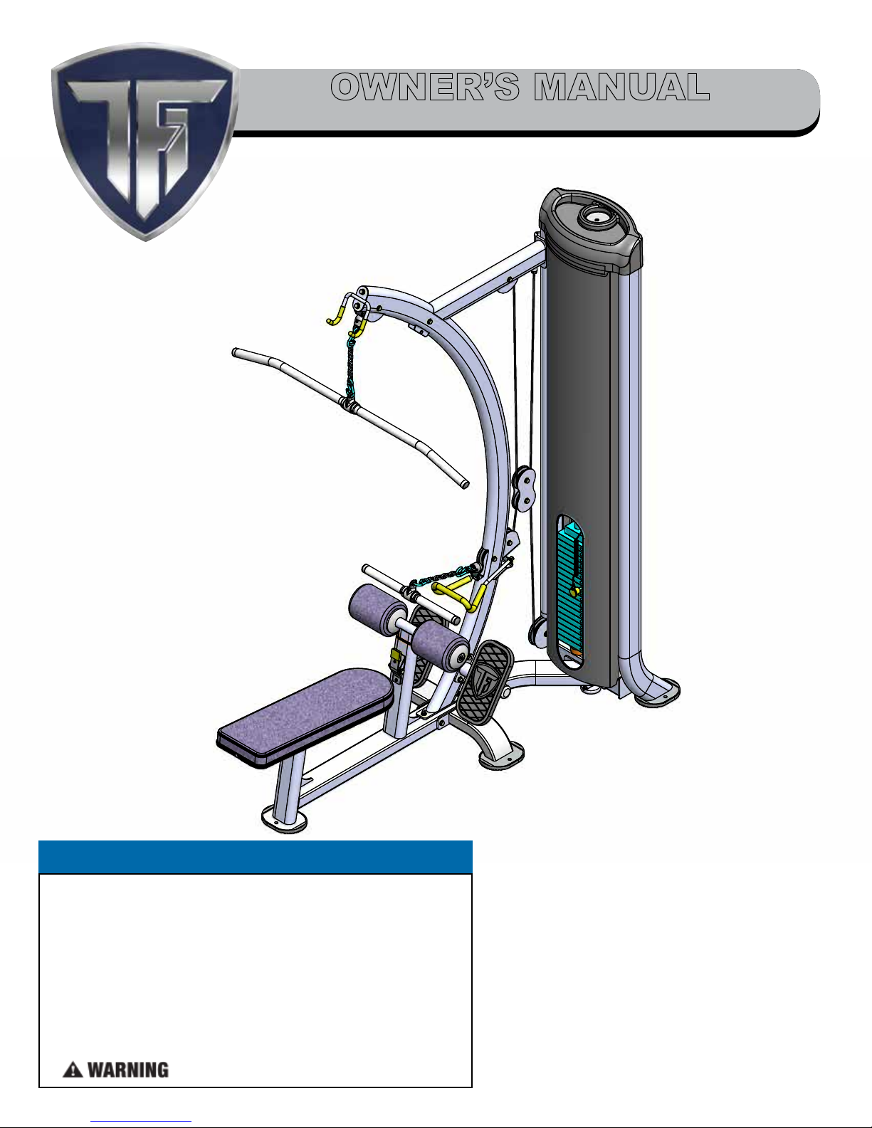
www.tustutness.comCG-9504 Lat/Mid Row 9
Important Safety Instructions
It is the responsibility of the facility owner and/or owner of the equipment to review the Owner’s Manual with their facility
personnel and understand all Danger, Warning and Caution labels axed on the machine. It is the responsibility of the oor
personnel to instruct users on proper operation of the equipment and review all danger, warning and caution labels.
SERIOUS INJURY OR DEATH CAN OCCUR
IF THESE SAFETY PRECAUTIONS ARE NOT OBSERVED:
1. Obtain a medical exam before beginning any exercise program.
2. Read and understand Owner’s Manual and all Danger, Warning
and Caution labels before using this equipment. If you still need
help, seek assistance from oor personnel.
3. Inspect the equipment before each use for wear and tear, loose
ttings, worn or frayed cables and frame welds. DO NOT USE if it
appears to be inoperable or damaged.
4. Stop exercising if you feel faint or dizzy. Consult a physician if you
are experiencing pain.
5. Use this equipment only for the intended use.
6. Keep body, clothing and hair clear from all moving parts. Do not
attempt to free any jammed parts by yourself.
7. Always warm-up before and cool-down after weight training.
Warm-up for 10-15 minutes with stretching and cardiovascular
exercises. Cool-down should include light stretching exercises for
5-15 minutes.
8. Never hold your breath – will limit the ow of oxygen to your brain
and may cause dizziness.The most often used breathing pattern is
inhaling during least resistance and exhaling during maximum
resistance.
9. Do not use accessories or accessory attachments that are not
recommended by TFI.
10. Make sure selector pin is completely inserted. Use only the selector
pin provided by the manufacturer.
11. Never pin the weights in an elevated position. Do not use the
machine if found in this condition.
Facility Safety Guidelines and Practices
1. Read and understand the Owner’s Manual before assembling,
servicing or using the equipment.
2. Equipment to be installed by TFI Authorized Dealer or
Professional Service Company approved byTFI.
3. Make sure each machine is set up and operated on a solid level
surface. Do not install equipment on an uneven surface.
4. Anchoring of equipment must be completed at time of
installation and inspected prior to use. Failure to anchor the
machine to the oor could cause the machine to tip or fall over
due to incorrect usage and misuse, and could result in serious
injury or death.
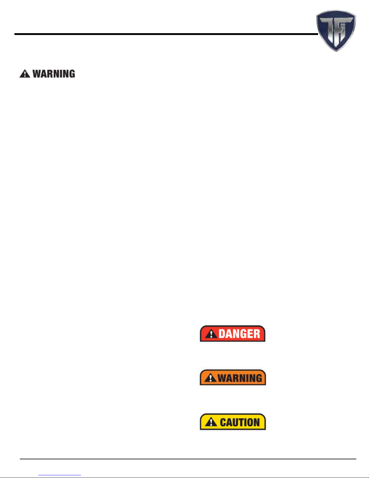
DANGER: indicates an imminently hazardous situation which, if not
avoided, will result in death or serious injury.
WARNING: indicates a potentially hazardous situation which, if not
avoided, will result in death or serious injury.
CAUTION: indicates a hazardous situation which, if not avoided, could
result in minor or moderate injury.
5. Provide an adequate safety perimeter between the machine,
walls and other equipment to ensure that the facility has proper
clearance for usage and training.
6. Post and disclose all safety, rules and regulations on a bulletin
board easily accessible to users.
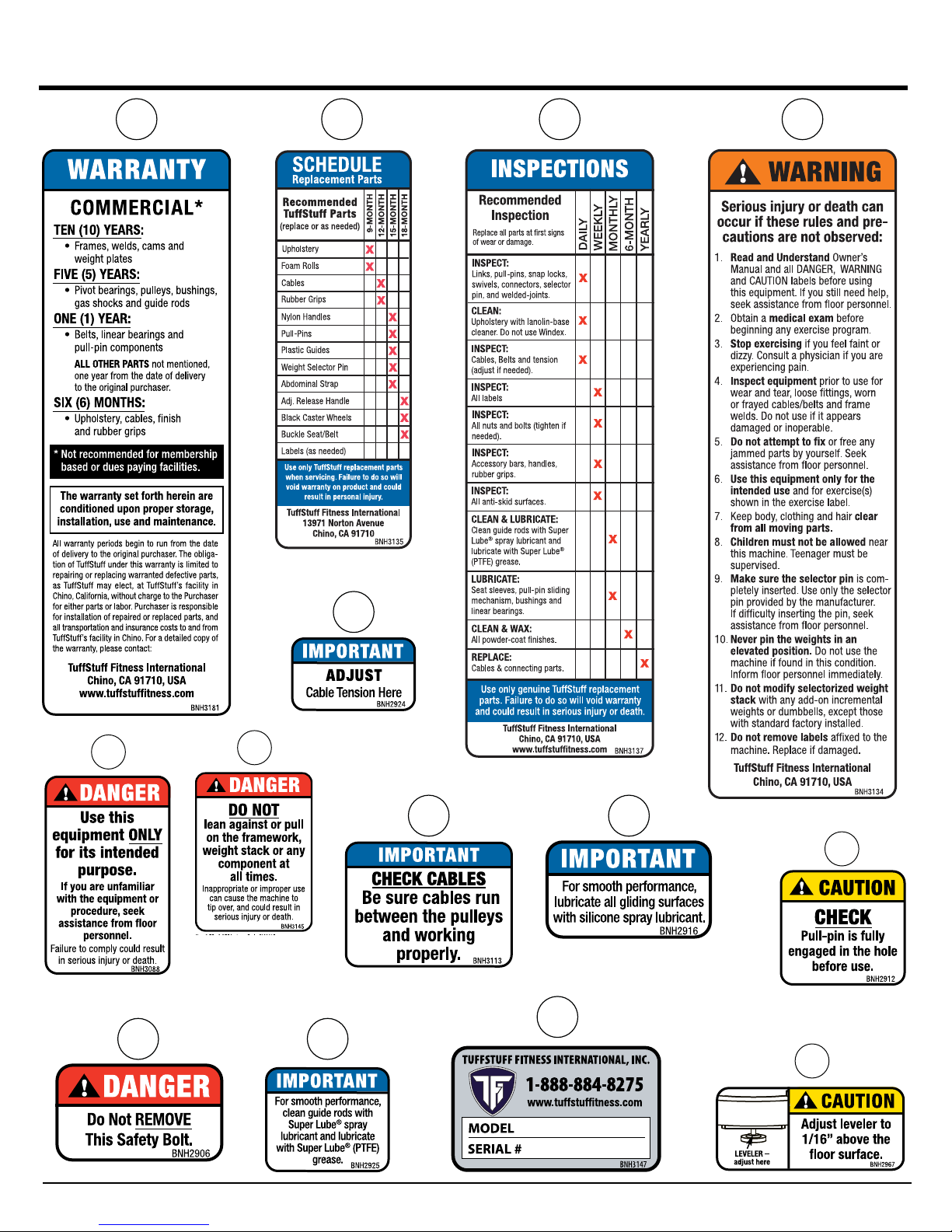
7. Perform regular maintenance (see Inspection Label). Pay special
attention to areas most susceptible to wear and tear, including but
not limited to cables, pulleys and rubber grips.
8. Do not lean against or pull on the framework, weight stack or
any component at all times.
9. Children must not be allowed near the equipment. Teenager must
be supervised.
10. Replace immediately all parts at rst sign of wear or damage. If
unable to replace worn or damaged components/parts, remove
machine from service until the repair is made.
11. Use only genuineTuStu replacement parts. Failure to do so will
void warranty and could result in serious injury or death to the users.
12. Do not remove any decals axed to the machine. Replace if
damaged.
13. Do not alter or modify the original manufacturer’s weight stack
with any add-on incremental weights, weight plates or
dumbbells except those with standard factory installed option.
14. Maintain a service contract with a TFI Authorized Dealer or a
Professional Service Company approved byTFI. Keep a service
log of all maintenance and repair activities. NOTICE: It is the sole
responsibility of the owner or facility operator to ensure that regular
maintenance is performed.

CG-9504 Lat/Mid Rowwww.tustutness.com
10
Thank you for purchasing the CG-9504 Lat/Mid Row. This machine is part of the
TuStu line of quality strength training equipment. To maximize your use of the equipment, please study the Owner’s Manual thoroughly.
Required Tools
The basic tools that you will need to assemble the CG-9504 but are not
limited to:
• 3/4”, 9/16”, 7/16”combination wrenches
• Adjustable wrench
• Ratchet wrench with 3/4”, 9/16”, 7/16” sockets
• Rubber mallet, measuring tape & utility knife
• Super Lube® spray lubricant and grease
• Windex or household glass cleaner
Assembly Requirements
Follow these installation requirements when assembling the
CG-9504. Use the overhead view on the Content Page to layout your oor
plan before assembling.
Set up the CG-9504 on a clean, solid, at surface. A smooth, at surface
under the machine helps keep it level.
Allow ample space around the machine for safe unrestricted use and
easier access.
Insert all bolts in the same direction. For aesthetic appearance, insert all
bolts in the same direction unless specied (in text or illustration) to do
otherwise.
Leave room for adjustments. Do not fully tighten fasteners until
instructed in the assembly steps to do so (to prevent any diculty with
alignment of parts during the assembly process). When not instructed,
tighten fasteners such as bolts, nuts and screws so the unit is stable, but
leave room for adjustments.
Assembly Tips
Read all“Notes”on each page before beginning each step.
While you may be able to assemble the CG-9504 using the illustrations
only, IMPORTANT safety notes and other tips are included in the text.
Some pieces may have extra holes that you will not use. Use only those
holes indicated in the instructions and illustration.
NOTE: With so many assembled parts, proper alignment and
adjustment is critical.While tightening the nuts and bolts,
be sure to leave room for nal adjustments.
CAUTION: Obtain assistance fromTFI if you have diculty
assembling the CG-9504. Please do not attempt to
complete the assembly as this could result in equipment
failure and serious injuries to the users.
Symbols & Description
Registration
To avoid unnecessary delays on warranty parts and to insure that a
permanent record of your purchase is on le with our company, be
sure to register online at http://www.tustutness.com or mail to
address shown below within 10 days of purchase.
Obtaining Service
Please use this Owner’s Manual as your guide to all parts included in
your shipment. When ordering parts, you must specify the part number
and description from this owner’s manual. Use only genuine TuStu
replacement parts when servicing the equipment. Failure to do
so will void warranty and could result in serious injury or death.
For information about product operation or service:
Phone: 909-629-1600 Toll Free 888-884-8275
Fax: 909-629-4967
E-mail: service@tustu.net or service1@tustu.net
Hours: M–F 8:00 – 4:30 PST
Or write to: TuStu Fitness International, Inc.
Customer Service
13971 Norton Avenue, Chino, CA 91710
Retain this Owner’s Manual for future reference when ordering
service or parts. To assist you better, please be prepared to
provide the following information:
1. Model Number 2. Place of Purchase
3. Serial Number 4. Part # and Description
Registration, Service & Assembly
Loosely Tighten
70%
100%
Fully Tighten
Loosely Tighten
Loosely tighten all hardware in this step. DO NOT Fully
Tighten. Some component(s) may need pre-assembly
and or alignment during the assembly process.
Fully Tighten
Wrench tighten all hardware in this step.

www.tustutness.comCG-9504 Lat/Mid Row 11
Perform regular maintenance (see Inspection Label). Pay special attention to areas most susceptible to wear and tear, including
but not limited to cables, pulleys and rubber grip. TFI recommends you maintain a service contract with a TFI Authorized Dealer or a
Professional Service Company approved by TFI. Keep a service log of all maintenance and repair activities. Extra copies can be downloaded
from our website www.tustutness.com
Inspection/Maintenance
INSPECTION / MAINTENANCE RECORDS
DATE REPLACEMENT REPAIRS INSPECTED BY
WARRANTY REPAIRS
DATE REPLACEMENT REPAIRS INSPECTED BY

CG-9504 Lat/Mid Rowwww.tustutness.com
12
Cable Inspection
WARNING:
THE FOLLOWING CONDITIONS MAY INDICATE A WORN CABLE� REPLACE IMMEDIATELY�
IMPORTANT NOTE:
DAMAGED OR WORN CABLE (AS SHOWN ABOVE) MAY DAMAGE THE PULLEY(S)� YOU MUST INSPECT THE
PULLEYS AT THIS TIME FOR WEAR AND TEAR� REPLACE IF NEEDED�
“NECKING”, STRETCHED CABLE COVERING
A TEAR IN THE CABLE COVER
CABLE END SLIPPING OUT
A CRACK IN THE CABLE COVER
A BREAK ON THE CABLE

www.tustutness.comCG-9504 Lat/Mid Row 13
39
33
45
33
*12
*18
Step 1 Assembly List
Item # Description Qty.
*12 MAIN FRAME 1
*18 WEIGHT STACK FRAME 1
33 FLAT WASHER SAE Z/P 3/8” 4
39 HEX HEAD CAP SCREW GR-5 Z/P 3/8-16 X 3 2
45 NYLON INSERT THIN PATTERN LOCK NUT Z/P 3/8-16 2
Step 1
100%
Fully Tighten
Fully Tighten
Wrench tighten all hardware in this step.
NOTE:
1. It is strongly recommended that 2
people participate in the assembly of
this unit.
2. Be sure to hold the weight stack frame
perpendicular to oor before tightening
the screws.

CG-9504 Lat/Mid Rowwww.tustutness.com
14
33
59
65
66
60
45
33
67
*6
39
*8
35
Step 2
100%
Fully Tighten
Fully Tighten
Wrench tighten all hardware in this step.
Step 2 Assembly List
Item # Description Qty.
*6 FRONT UPRIGHT 1
*8 LAT BAR HOLDER 1
33 FLAT WASHER SAE Z/P 3/8” 4
35 HEX HEAD CAP SCREW GR-5 Z/P 3/8-16 X 1 2
39 HEX HEAD CAP SCREW GR-5 Z/P 3/8-16 X 3 2
45 NYLON INSERT THIN PATTERN LOCK NUT Z/P 3/8-16 2
59 SPLIT LOCK WASHER Z/P 3/8” 2
60 SPLIT LOCK WASHER Z/P 1/2” 2
65 FLAT WASHER SAE Z/P 1/2” 2
66 HEX HEAD CAP SCREW GR-5 Z/P 1/2-13 X 1 1/4 2
67 FLAT WASHER 3/8 ID X 1 1/2 OD X 3/16 THICK 2

www.tustutness.comCG-9504 Lat/Mid Row 15
*100
33
33
*15
40
33
39
*5
45
33
45
*15
Step 3
100%
Fully Tighten
Fully Tighten
Wrench tighten all hardware in this step.
Fully Tighten
Wrench tighten all hardware in this step.
Step 3 Assembly List
Item # Description Qty.
*5 FOOT PLATE 1
*15 STABILIZER 2
33 FLAT WASHER SAE Z/P 3/8” 8
39 HEX HEAD CAP SCREW GR-5 Z/P 3/8-16 X 3 2
40 HEX HEAD CAP SCREW GR-5 Z/P 3/8-16 X 5 2
45 NYLON INSERT THIN PATTERN LOCK NUT Z/P 3/8-16 4
86 LABEL DANGER DO NOT REMOVE... 7/8 X 1-1/2 1
*100 FOOT PLATE 1

CG-9504 Lat/Mid Rowwww.tustutness.com
16
59
37
14
7
7
69
68
45
33
33
3626
52
33
Step 4
Step 4 Assembly List
Item # Description Qty.
7 GUIDE ROD 3/4 RD X 76 1/4 (CG-9500 SERIES) 2
14 SELECTOR PIN W/COIL 3/8 X4 GOLD KNOB 1
26 BLACK NYLON PULLEY 3/8 X 1 X 3 1/2 (P-35375-H) 1
33 FLAT WASHER SAE Z/P 3/8” 4
36 HEX HEAD CAP SCREW GR-5 Z/P 3/8-16 X 1 1/4 2
37 HEX HEAD CAP SCREW GR-5 Z/P 3/8-16 X 1 3/4 1
45 NYLON INSERT THIN PATTERN LOCK NUT Z/P 3/8-16 1
52 RUBBER DONUT 3/4 X 2 1/2 4
59 SPLIT LOCK WASHER Z/P 3/8” 2
68 10 LB STEEL WEIGHT PLATE BLACK 4 X 10 19
69 10 LB TOP PLATE W/ADJ SLTR BAR 19 BLK WTS ASM 1
100%
Fully Tighten
Fully Tighten
Wrench tighten all hardware in this step.

www.tustutness.comCG-9504 Lat/Mid Row 17
Fully Tighten
Wrench tighten all hardware in this step.
Weight stack label and lubrication instructions
1� Wipe front surface of weight stack with rubbing alcohol and wipe dry�
2� Peel o back sheet (adhesive side) from label (#79) and make sure that the label remains
attached to the application tape�
3� Line up left edge of label sheet with outside edge of weight holes�
4� Line up the rst label to hole on top plate�
5� Make sure label is straight and slowly press into place�
6� Gently remove application tape and rub each label rmly against the weight stack�
7� Allow labels to stand for 2 days to allow adhesive to cure fully�
8� Open the lube package provided and apply a thin lm of lubricant around the rst 3 inches
of the guide rods above the top plate�
9� After the cables are installed, do a set of reps to spread the lubricant thoroughly�
NOTE:
1� TOP PLATE LABEL GOES ON HOLE OFF CENTER AS
SHOWN� LABEL WILL COVER HOLE ON CENTER�
79

CG-9504 Lat/Mid Rowwww.tustutness.com
18
60
57
9
41
9
*3
56
41
47
70
27
20
56
Step 5 Cable Routing
Use guide wire to route the cable

www.tustutness.com 19
CG-9504 Lat/Mid Row
Step 5 Assembly List
Item # Description Qty.
*3 DOUBLE PULLEY PLATE 1
9 LAT CABLE 1
20 7/8 RD X 2 15/32 LINK 3/16 CABLE 1
27 CABLE STOPPER SHELL SØ1.5 X 1.75 1
41 LAT BAR 1 1/4 ALUMINUM 1
47 OVAL HEAD SCREW Z/P #10-24 X 1 1/8 1
56 SNAP LINK Z/P 8MM X 80MM 2
57 SPLIT BOLT GR-5 Z/P 1/2-13 X 1 1/4 (RND CUT) 1
60 SPLIT LOCK WASHER Z/P 1/2” 1
70 COIL CHAIN Z/P 3/16 X 8 1
100%
Fully Tighten
Fully Tighten
Wrench tighten all hardware in this step.

CG-9504 Lat/Mid Rowwww.tustutness.com
20
Step 6 Cable Routing
25
58 30
60
69
11
14
43
11
56
43
27 11
70
47
20
56
Table of contents
Other Tuff stuff Elliptical Trainer manuals
Popular Elliptical Trainer manuals by other brands

SereneLife
SereneLife SLEPL9 user manual

Star Trac
Star Trac Pro CrossTrainer Elite CrossTrainer Service manual

HEALTH RIDER
HEALTH RIDER E660 HREL09982 user manual

HEALTH RIDER
HEALTH RIDER Crosstrainer 2000s Elliptical Manuale d'istruzioni

Pro-Form
Pro-Form 585 Cse Elliptical manual

Pro-Form
Pro-Form PFEL5055 user manual