1. CORRECT APPLICATION
BrakeMate® is to be used only as described in this Operating Manual.
The BrakeMate® Hub/Rotor Trolley and the BrakeMate® Service Trolley are
engineered specifically for this task and are not to be used for general lifting or any
other purpose. BrakeMate® is designed to be used in a workshop environment on a firm,
level surface.
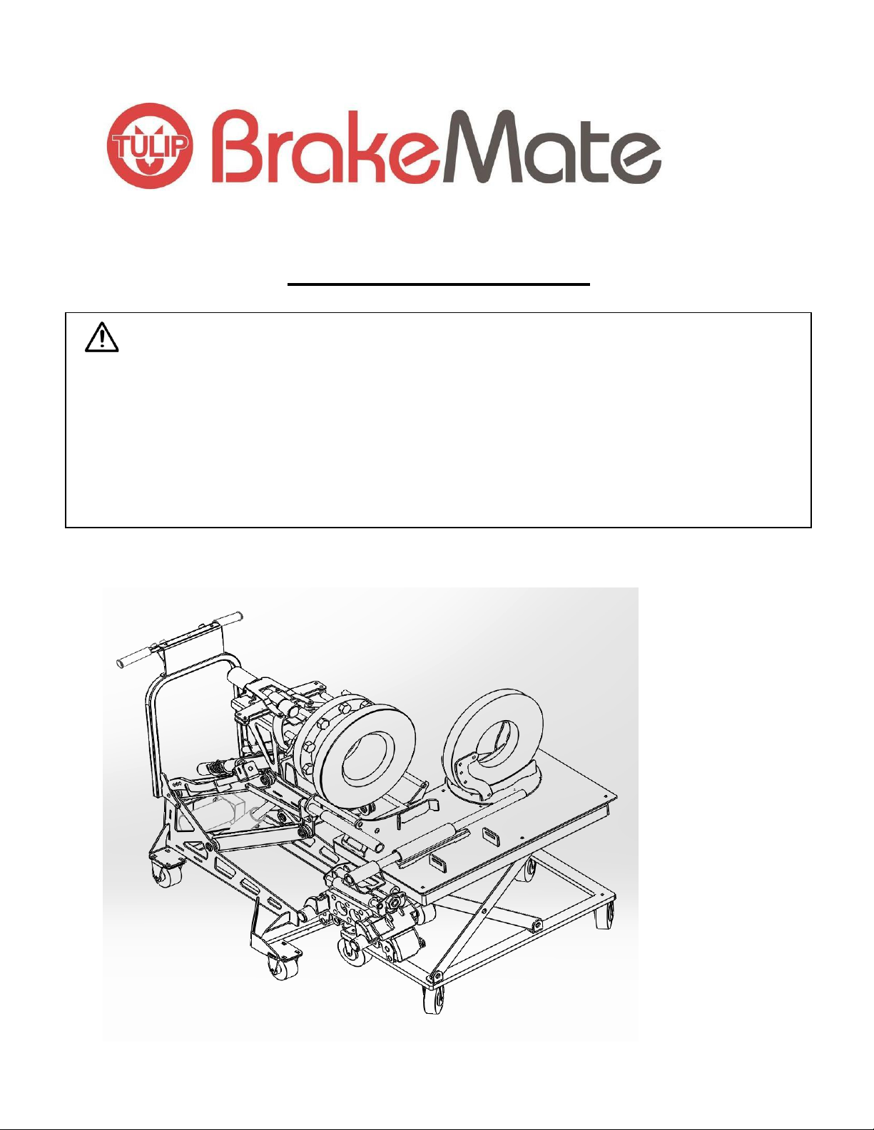
2. DESCRIPTION OF BRAKEMATE® SYSTEM
a. SYSTEM OVERVIEW
BrakeMate® is designed to eliminate the need for manual lifting of heavy brake
components when servicing disc brakes and bearings on heavy vehicles. The system
also utilises hydraulics to remove the hub/rotor assembly from the vehicle and
separate these components. BrakeMate® is comprised of two trolleys, the Hub/Rotor
trolley and the Service Trolley.
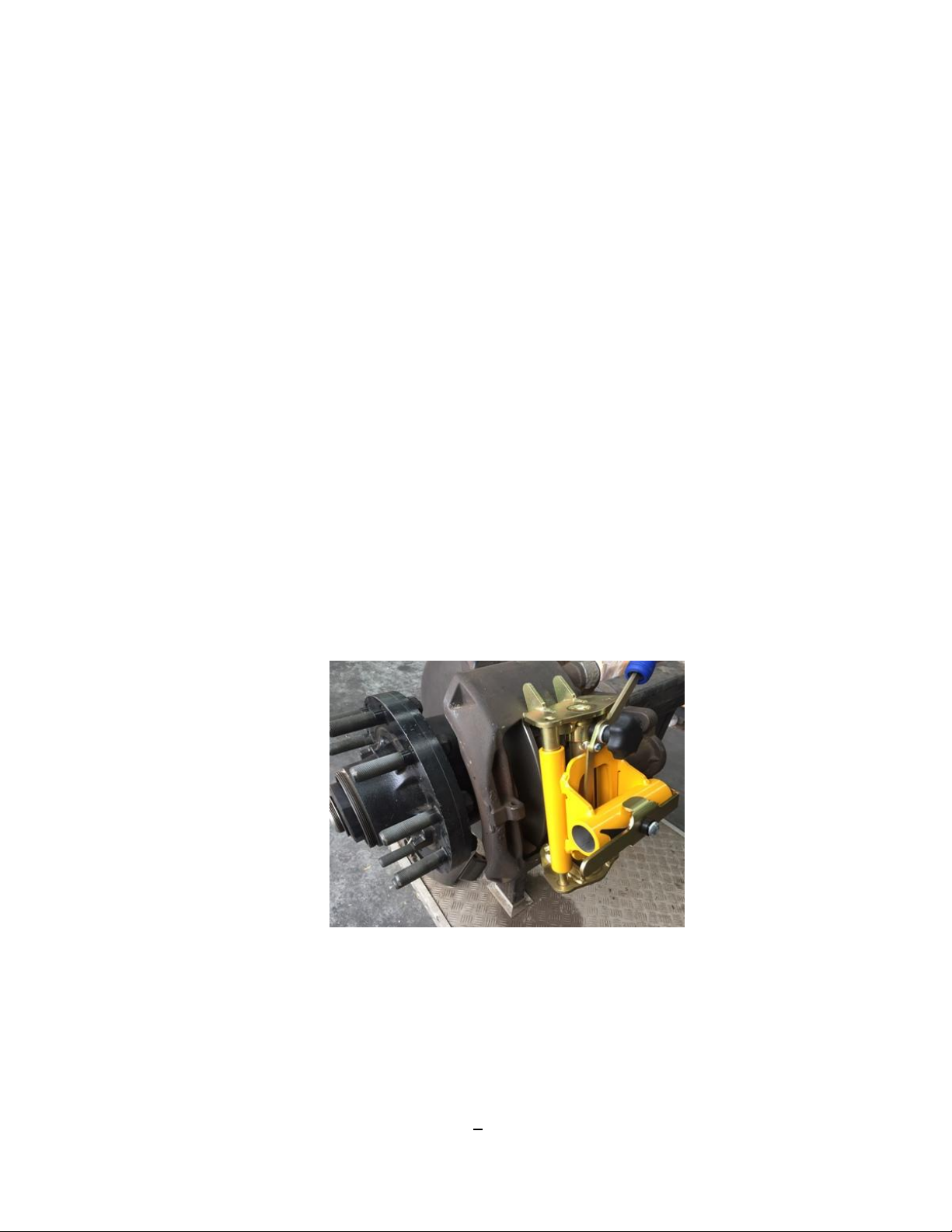
BrakeMate® is designed to assist with the following tasks.
- Removing and refitting calliper.
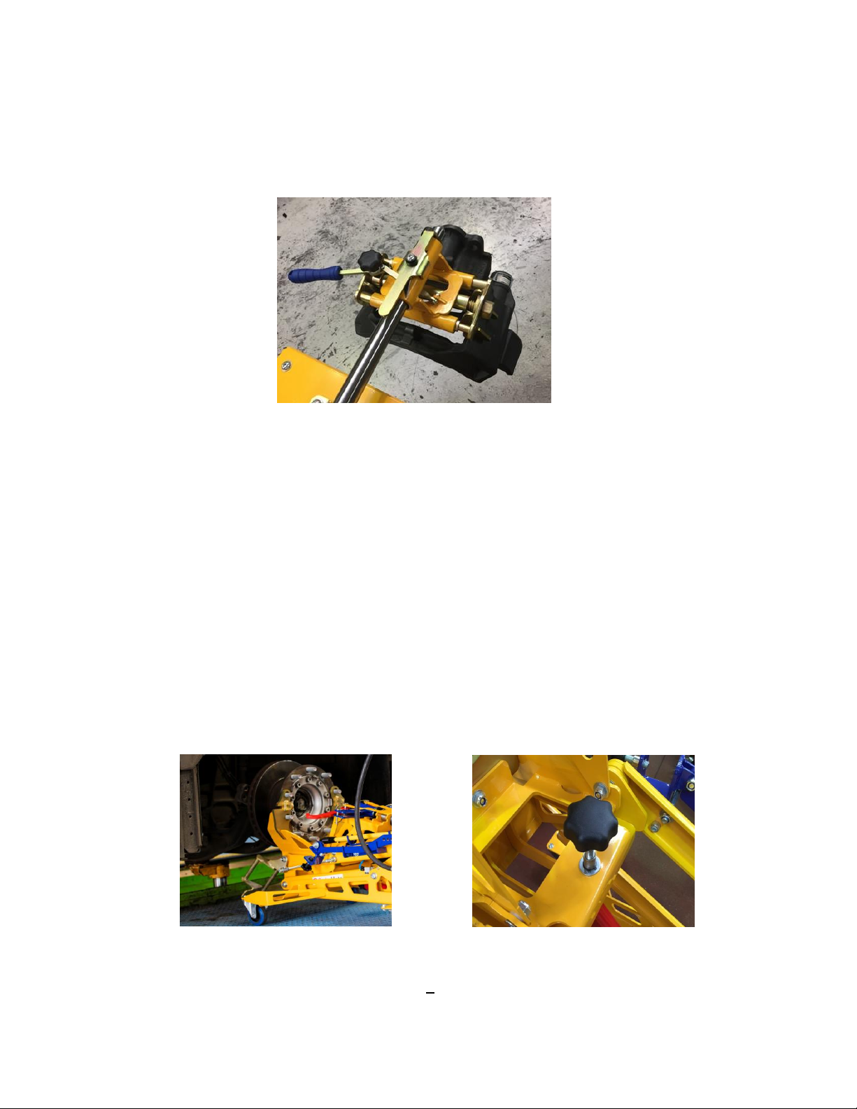
- Removing and refitting hub and rotor.
- Separation of hub and rotor.
- Changeover of rotors.
-Controlled realignment of hub to axle.
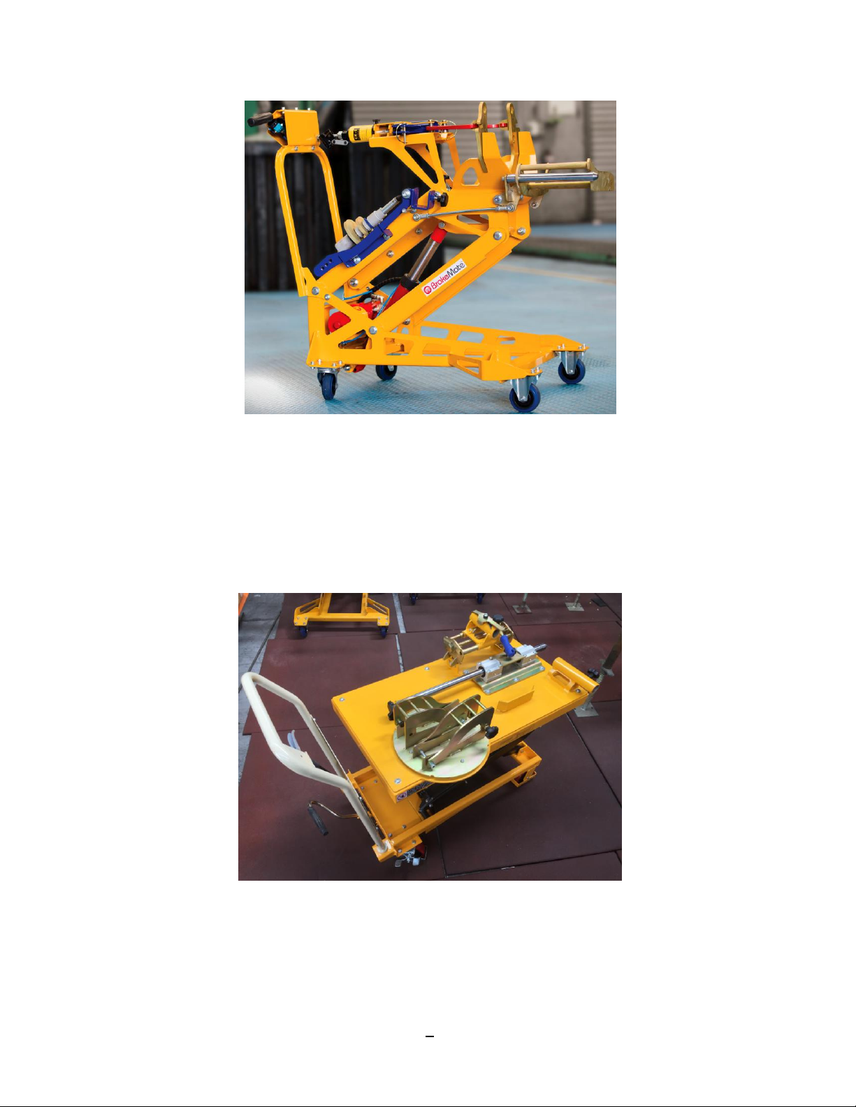
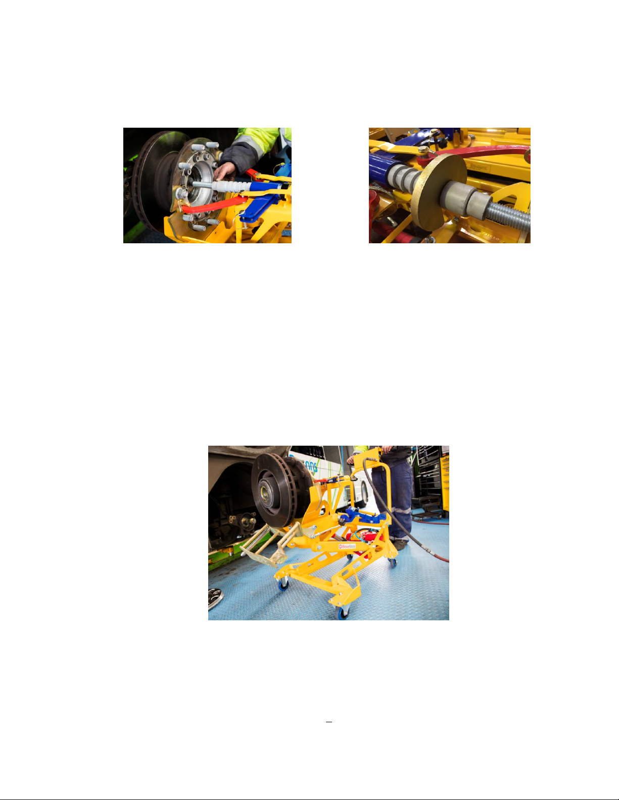
b. MAIN TECHNICAL DATA
Hub/Rotor Trolley (Fig. 1)
The BrakeMate® Hub/Rotor Trolley is operated by an air over hydraulic system. The air
operated hydraulic pump is rated at 5000 PSI and controls the up/down motion of the
trolley via the main ram. A limit switch stops the unit at working height and also protects
the ram from over travel. An additional manually operated10 tonne hydraulic ram is
used to remove the hub from the axle and separate the hub/rotor assembly.
Service Trolley (Fig. 2)
The BrakeMate® Service Trolley contains a manual hydraulic ram controlled by a foot
pump and pressure release lever. The Service Trolley has a maximum lift height of
1300mm.
3