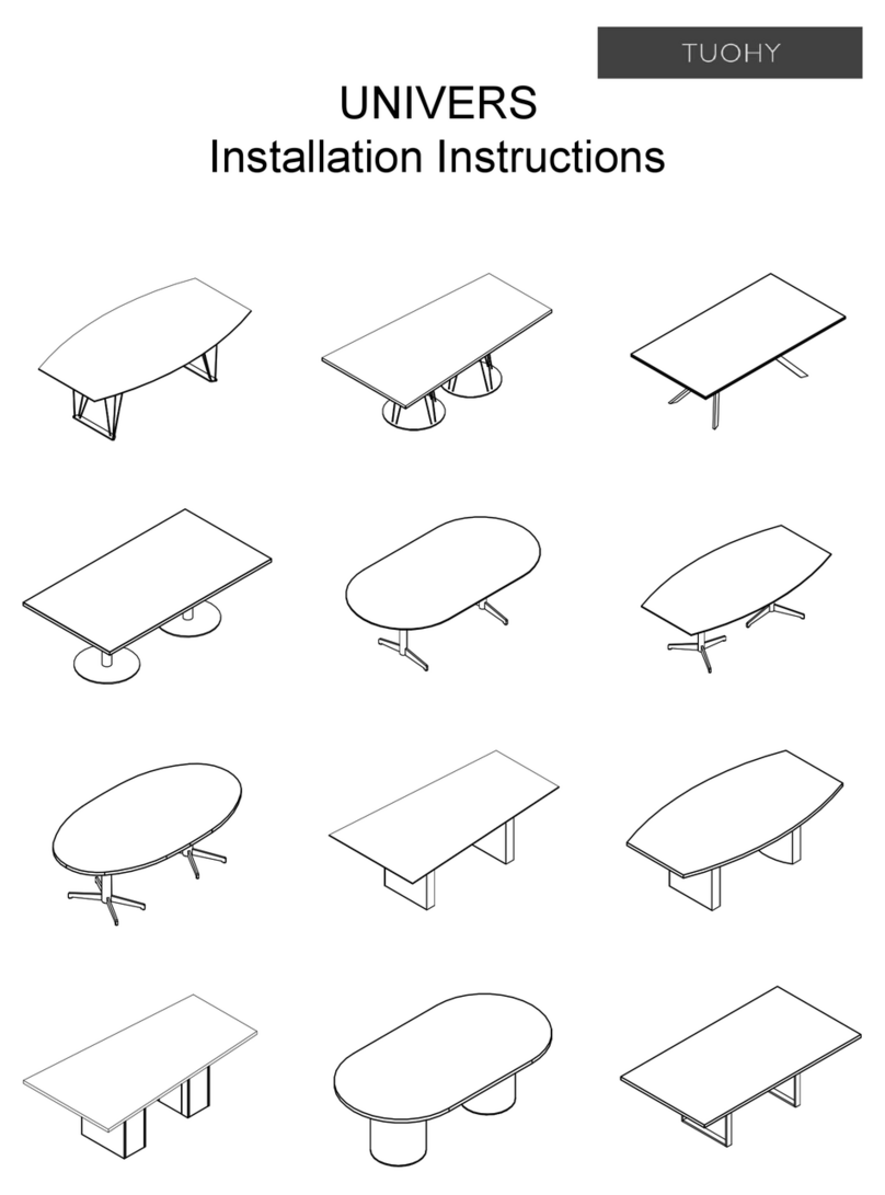
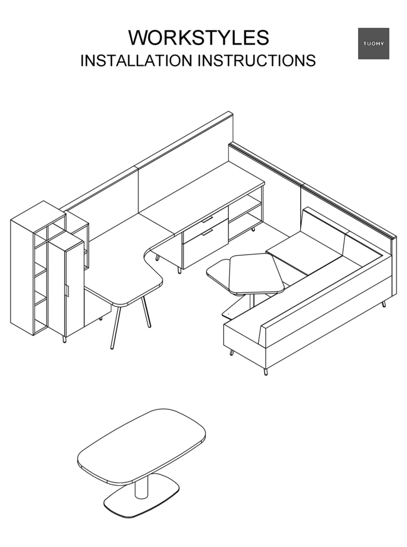
Tuohy ANDAVI User manual

ANDAVI
Installation Instructions

Table of Contents
Hardware / Parts List . . . . . . . . . . . . . . . . . . . . . . . . . . . . 1
Typical Connections . . . . . . . . . . . . . . . . . . . . . . . . . . . . 2
Starting Section - Frame . . . . . . . . . . . . . . . . . . . . . . . . . 4
Starting Section - Cabinets . . . . . . . . . . . . . . . . . . . . . . . . . . 5
Next Section - Frame / Cabinets. . . . . . . . . . . . . . . . . . . . . . . . 6
End Cabinets . . . . . . . . . . . . . . . . . . . . . . . . . . . . . . 7
Fixed Height Runoffs . . . . . . . . . . . . . . . . . . . . . . . . . 8
Adjustable Height Runoffs . . . . . . . . . . . . . . . . . . . . . . . . . 9
Electrical . . . . . . . . . . . . . . . . . . . . . . . . . . . . . . . . 10
Lighting . . . . . . . . . . . . . . . . . . . . . . . . . . . . . . . . . . 11

1
HARDWARE / PARTS LIST:
Cabinet Supports & Mounting Brackets
Single Cabinet Support Double Cabinet Support
Pedestal Bracket
10" Z-Clip Z-Clip Mount Support
#8 x 3/4" Flat Head
1/4-20 x 1/2"
Button Socket Cap Screw 1/4-20 Drop-In
T-Nut
#8-32 X 1/2"
Button Head Screw Confirmat Screw
Fasteners
#9 X 5/8" Panhead
Cross Strap
A = 14.25" (For use to install 12" cabinets)
A = 20.25" (For use to install 18" cabinets)
A = 26.25" (For use to install 24" cabinets)
A = 32.25" (For use to install 30" cabinets)
A = 38.25" (For use to install 36" cabinets)
Bridge Plate Runoff Leg
Wire Chase #10 X 1" Panhead
#9 X 1 1/4" Flat Head
Cable Tie
Mount Block 6" Cable
Zip Tie

2
TYPICAL CONNECTIONS
CABINET SUPPORT
Attach to extrusion using 1/4-20 Drop-In T-Nut
and 1/4-20 x 1/2" Button Socket Cap Screw
DETAIL A
Typical T-Nut Fastener Installation Instructions
These General Instructions Shall
Apply to All Bracket and Plate
Connections that Require T-Nut
Fasteners as Part of the Connection.
- Insert 1/4-20 x 1/2" BSCS Thru Hole
in Plate / Bracket & Thread T-Nut
2-Turns Onto Bolt. Repeat for Rest
of Connection Holes.
- Next, Align T-Nuts so they Match the
Extrusion Being Connected &
Depress Into Channel.
- Should Look Like This Before
Further Tightening Takes Place.
ATTENTION :
- As Initial Tightening of Each BSCS
Begins, T-Nuts Must Pivot in Channel
Engaging the Shoulders of T-Nut
Against the Walls of the Channel.
- Pay Special Attention that Each T-Nut
"Engages" Before Continuing to
Tighten Each Bolt.
CORRECT INCORRECT
Shoulders Did Not Engage
Into Sides of Channel.
Z-CLIP MOUNTING BRACKET
Attach Z-Clip Mounting Bracket using 1/4-20 Drop-In
T-Nut and 1/4-20 x 1/2" Button Socket Cap Screw
DETAIL B
Slide T-Nut into
opening of post
and into place.
Engage T-Nut
and Tighten.

3
TYPICAL CONNECTIONS
LIGHTING WIRING DETAIL
Insert wires through post to conceal them.
Add wire extentions as needed.
Z-CLIP
Screw Z-Clips to tower using
#8 X 3/4" Flat Head Screws
DETAIL J
DETAIL H
(underside view)
PEDESTAL BRACKET
Attach to extrusion using 1/4-20 Drop-In T-Nut
and 1/4-20 x 1/2" Button Socket Cap Screw.
Screw to side
of pedestal
using #9 x 5/8"
Pan Head
Screws.
CROSS STRAPS
Attach to cabinet support using #8-32 x 1/2"
Button Head Screw.
Attach so cross strap
is fully extended.
CABINETS
Screw cabinets to cabinet supports using
#8 x 3/4" Flat Head Screws
DETAIL C
DETAIL E
DETAIL F DETAIL G
DETAIL D (underside view)
Guide wires behind
T-Nuts to follow all
the way through post
to electrical cabinet. Center Z-Clip left
to right on case.
(See page 7 for
more details)
Add wire extentions as needed. Wire
connectors will not fit into post behind
T-Nuts. Wire extentions much be
attached after wires are routed.
Guide wires down
post to conceal them
and into electrical
cabinet.

4
DOUBLE
CABINET
SUPPORT
STARTING SECTION - FRAME
* See provided layout for specific unit purchased.
* Start at LH section and work towards RH section (Hanging cabinets are to be installed last).
1. Pre-assemble each side with cabinet supports in approximate locations (see detail A)
2. Attach cross straps to highest and lowest cabinet supports (see details C & D)
** Be sure to use appropriate sized cross straps for width of cabinets in section**
3. Level cabinet supports with each other and tighten fasteners
DOUBLE
CABINET
SUPPORT
SINGLE
CABINET
SUPPORT
SINGLE
CABINET
SUPPORT
SINGLE
CABINET
SUPPORT
CROSS
STRAPS
SINGLE
CABINET
SUPPORT
** ATTENTION **
Be sure to attach
cabinet supports for
cabinets going off
BOTH sides of post
CROSS
STRAPS
Pre-assemble each
frame section with
cabinet supports prior
to attaching cross
straps.
Level
Level
Level

5
STARTING SECTION - CABINETS
* Insert cabinets top to bottom
1. Insert top cabinet into location and align with post
- 18" deep cabinets: case will be flush with front and back
- 21" deep cabinets: case will be flush with front or back
(see provided drawings specific to unit to determine if cabinet should be flush with front or back)
2. Slide cabinet tight to post on one side and screw to cabinet support (see detail E)
3. Loosen cross strap (do not remove completely)
4. Pull cabinet tight to other side & screw to cabinet support
5. Attach L-brackets, 2 per side of cabinet (see details F & G)
**Position L-brackets so adjacent cabinet will hide them**
6. Remove upper cross straps
7. Repeat steps 1-5 with remaining cabinets moving downward
8. Remove lower cross straps after lowest
cabinet has been installed
Loosen cross strap and pull
cabinet tight to side prior to
screwing to support bracket
to remove gap
Install 1st.
Screw to
support
brackets and
remove
upper cross
straps prior
to installing
cabinet
below
Install 3rd.
Screw to
support
brackets and
remove lower
cross straps
**Position L-brackets
so adjacent cabinet
will hide them**
'A' = 78" for 96" tall units
'A' = 54" for 69" tall units
No gap between
post and cabinet Install 2nd.
Screw to
support
brackets
prior to
installing
cabinet
below
Electrical housing box can
be installed at any time
after cabinet is installed
(See page 10)

6
NEXT SECTION - FRAME
* See provided layout for specific unit purchased.
1. Pre-assemble next frame section with cabinet supports in approximate locations (see detail A)
2. Attach cross straps (see details C & D)
3. Level cabinet supports with each other and tighten fasteners
Pre-assemble
next frame
section with
cabinet
supports prior
to attaching
cross straps.
NEXT SECTION - CABINETS
* Install cabinets the same as the starting section cabinets.
See page 5 for details.
(Only the starting section will have pedestal L-brackets on
both sides. All remaining sections will have L-brackets
attached on one side only)
REPEAT PAGE 6 UNTIL ALL FRAME
SECTIONS HAVE BEEN ADDED.
CONTINUE TO PAGE 7 TO INSTALL END CABINETS.
** ATTENTION **
Install any necessary
wiring for lighting
BEFORE installing next
set of cabinets
(See detail J)
Level
Level

7
END CABINETS
1. Attach Z- Clip Mounting Brackets to extrusions (see detail B)
2. Attach Z-Clips to cabinet (see detail H)
3. Slide cabinet down into place on Z-Clip Mounting Brackets so Z-Clips securely attach.
4. Align cabinet into place
- 18" deep cabinets: case will be flush with front and back
- 21" deep cabinets: case will be flush with front or back
(see provided drawings specific to unit to determine if cabinet should be flush with front or back)
5. Screw cabinet to bottom cabinet support bracket (see detail E)
Dimension
point
Once cabinet is securely
attached on Z-Clip Mounting
Brackets and aligned into
place, screw cabinet to
bottom cabinet support

8
FIXED HEIGHT RUNOFF
** Runoffs are always connected to electrical cabinet **
1. Attach runoff legs to runoff top
- Align legs with milled holes on
runoff top, 1/4" inset from edges.
- Screw legs to top using
#9 x 1 1/4" Flat Head Screws
2. Mount optional dimmer controller
into hole on underside of table
(See page 11 for details)
3. Attach bridge plates to cabinet
- Screw bridge plate to underside
of electrical cabinet using
#10 x 1" Pan Head Screws
4. Attach runoff to cabinet
- Screw runoff top to bridge plates
using #10 x 1" Pan Head Screws
Mount
Dimmer
Controller
(optional)
Mount
Dimmer
Controller
(optional)

9
ADJUSTABLE HEIGHT RUNOFF
** Runoffs are always connected to electrical cabinet **
1. Place adjustable height leg/plinth
into approximate location.
'A' = Runoff width
2. Temporarily connect electrical cords
for legs and keypad to control box.
Plug control box into outlet &
raise legs out of plinth and cabinet.
3. Install mounting plate to leg
using M8 1.25 x 18mm
Flat Socket Cap Screws
4. Attach Runoff top to
mounting plates on legs
- Be sure plinth is in correct location
- Raise legs up to allow access
to screw into plates
- Screw runoff top to mounting
plates using #12 - 8 x 1"
Pan Head Button Screws
5. Mount optional dimmer controller
into hole on underside of table
(See page 11 for details)
6. Re-wire
electrical
cords to
conceal in
electrical
cabinet
Mount Dimmer Controller
(optional)

ELECTRICAL & WIRING
ELECTRICAL HOUSING BOX
1. Remove bottom cross straps
prior to installing
2. Slide box under cabinet into place
(access door to face
towards side of cabinet
3. Screw (x4) Confirmat screws
down through bottom of
cabinet into box
WIRE CHASE
1. Remove false back in upper cabinet
2. Slide wire chase through cutout in upper
cabinet down into cutout in lower cabinet
3. Use tape squares to secure wire chase
into place
4. Replace false back in upper cabinet
ROUTING WIRES
1. Mount power supply, receiver, and
mounting block for lighting in electrical
cabinet
2. Route electrical cords for televisions,
computer monitors, etc through wire
chase and into electrical cabinet
3. Wires for lighting are routed down
through posts into electrical cabinet
Access
door
(doors hidden)
Place tape
squares
under edge
to secure
into place
10

Receiver Specifications:
Remote Specifications:
Output Voltage: 12V DC
Max-Output Load: 5A, 60W
Dimming Range: 100% - 1%
Installation Instructions
Single Zone Wireless Round Dimmer
12V DC 60WCapacity
READ ALL INSTRUCTIONS BEFORE INSTALLING SYSTEM.
Before beginning installation, be sure power is turned OFF to light system.
Programming Instructions:
Tresco Lightingby Rev-A-Shelf
Tel: 800-227-1171
Fax: 502-491-2215
Email: cservice@trescolighting.com
Web: www.trescolighting.com
+
6.89”
25%
75%
Dimming
Z
PROGRAM BUTTON
*Under access cover
L-DC-ELT18-CON
L-DC-ELT60-CON
L-DC-ELT18-CON
L-DC-ELT60-CON
Learning Key
Dimmer Receiver
123
4
7
5
8
6
25% 50%
75% 100%
SS
Power Supply
Mounting Block
Figure 2
Figure 3
4" (101 mm)
Input Wire
Output Wire
Male AMP®
Connector
Save these instructions for
future reference.
For technical assistance: 1-800-227-1171
Female AMP®
Connector
4" (101 mm)
Figure 1
I-WLDIM1RND-1015
1. Disconnect Mounting Block from 12V DC Tresco power supply (see spec
guide for power supply options). Connect Dimmer Receiver to Tresco 12V DC
power supply by locating the input wire to the receiver and snapping the male
AMP connector to female AMP connector located on output wire of the power
supply (Figure 2).
*To use multiple receivers on one power supply, connect the input wire of the Mounting Block to the
power supply output and then plug the receivers into the Mounting Block.
2. Take the mounting case o of the Round Dimmer Controller (gure 1).
Remove the clear plastic tab to activate the battery.
3. Plug desired light(s) into the Mounting Block.
4. Plug polarized 2-prong end of Tresco 12V DC power supply wire into 120V
receptacle. If receptacle is operated by on/o wall switch, turn switch on aer
plugging power supply in.
5. Press (do not hold down) the Learning Key (gure 3) on the Dimmer
Receiver once, then press (do not hold down) the power button on the Round
Dimmer Controller once. The lights should flash on/off, indicating they are
programmed properly.
6. Repeat step 5 with any additional receivers or controllers that you want
programmed.
*Each receiver can be controlled by up to 8 different controllers. A single controller can
control up to 10 receivers.
Round Dimmer Controller
How to Deprogram a Receiver:
1. Hold down the Learning Key on the Dimmer Receiver until the lights
connected to the receiver ash on/o twice.
2. The receiver is now reset and is no longer programmed to any controllers.
IMPORTANT SAFETY INSTRUCTIONS
CAUTION: To reduce the risk of fire, electric shock, or injury to persons:
• Route and secure cordssotheywill not be pinched or damaged when cabinet is pushed
to the wall.
•Use only insulated staples orplastic ties to secure ALL loose cords.
• 12VDC input only to receiver
• 12VDC 60W 5AMP max receiver output
•Use only in dry locations. Not foruse where exposed to the weather
• All wiring must follow NEC regulations.
Dimmer Receiver
1-1/2”
(38 mm)
5/8”
(19 mm)
Dimmer Mounting Instructions:
1. There are three options for mounting: screws (Figure 4), magnet (located on
bottom of casing), or double-stick adhesive (included in package).
2.To mount with screws, first remove the casing from the dimmer. Position the
casing at desired location, being sure to align the "notch" on the inner wall of the
casing (Figure 5) at the top of the cylinder to ensure proper orientation of the
control button on the Dimmer.
Figure 4
Figure 5Alignment
Notch
Dimmer Casing
3.Mark screw hole locations and use a 1/16" drill bit for pilot holes. Drive screws
the through holes in casing into pilot holes, again ensuring that the notch on
casing is at the top portion of the cylinder.
4.Slide Dimmer control unit into Dimmer casing (Figure 6).
Figure 6
•Replace battery with CR2025 Battery only. Not rechargeable.
Operating Voltage: 3V CR2025 battery Input Voltage: 12V DC
916.5 MHz
11
Table of contents
Other Tuohy Indoor Furnishing manuals
Popular Indoor Furnishing manuals by other brands

Epoch Design
Epoch Design VERONA 5415 Assembly instructions

Furinno
Furinno 15095 Assembly instruction

firplak
firplak Thalos Class Cabinet Assembly instructions

modway
modway EMPRESS ARM quick start guide

Kimball Office
Kimball Office Itsa K38AA Adjustment instructions

Furniture of America
Furniture of America Christie CM7540CK Assembly instructions