1
WALL PANELS & SHELVING
** Wall panel wood shelving support posts and 1/4" metal shelves
must be installed in wall panel prior to securing wall panel to wall.
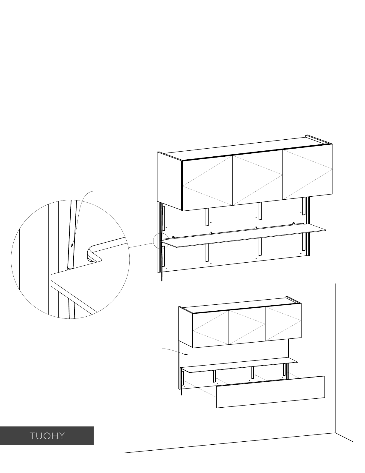
Wall Panel Shelving
1. Attach french cleat to wall.
** To be used as installation aid only.
(Installer responsible for attachment hardware)
2. Secure wall panel to wall.
** Do NOT rely on french cleat only!
** Panel must be secured to wall throughout
panel using the pre-drilled holes to obtain
maximum shelf weight.
Toggle fasteners are recommended.
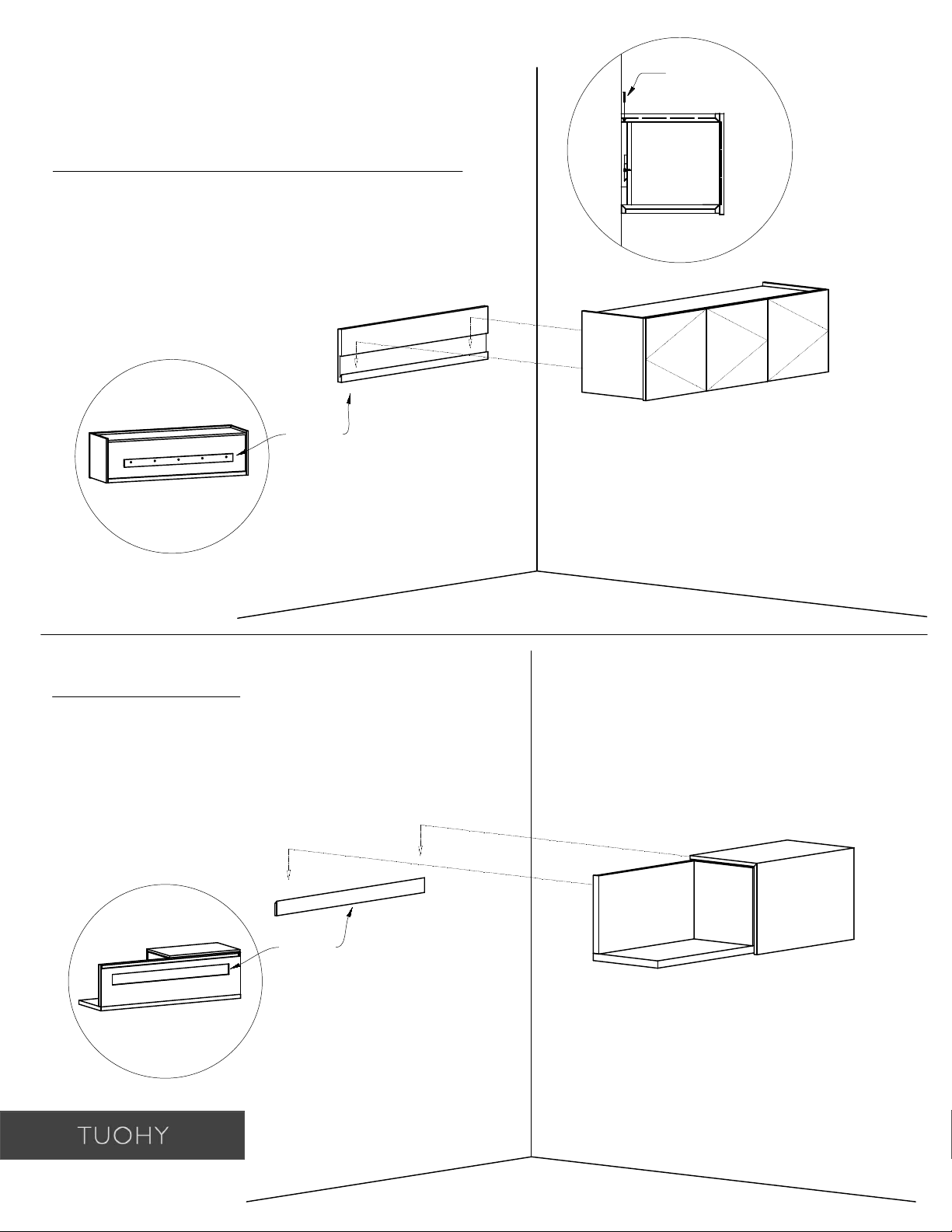
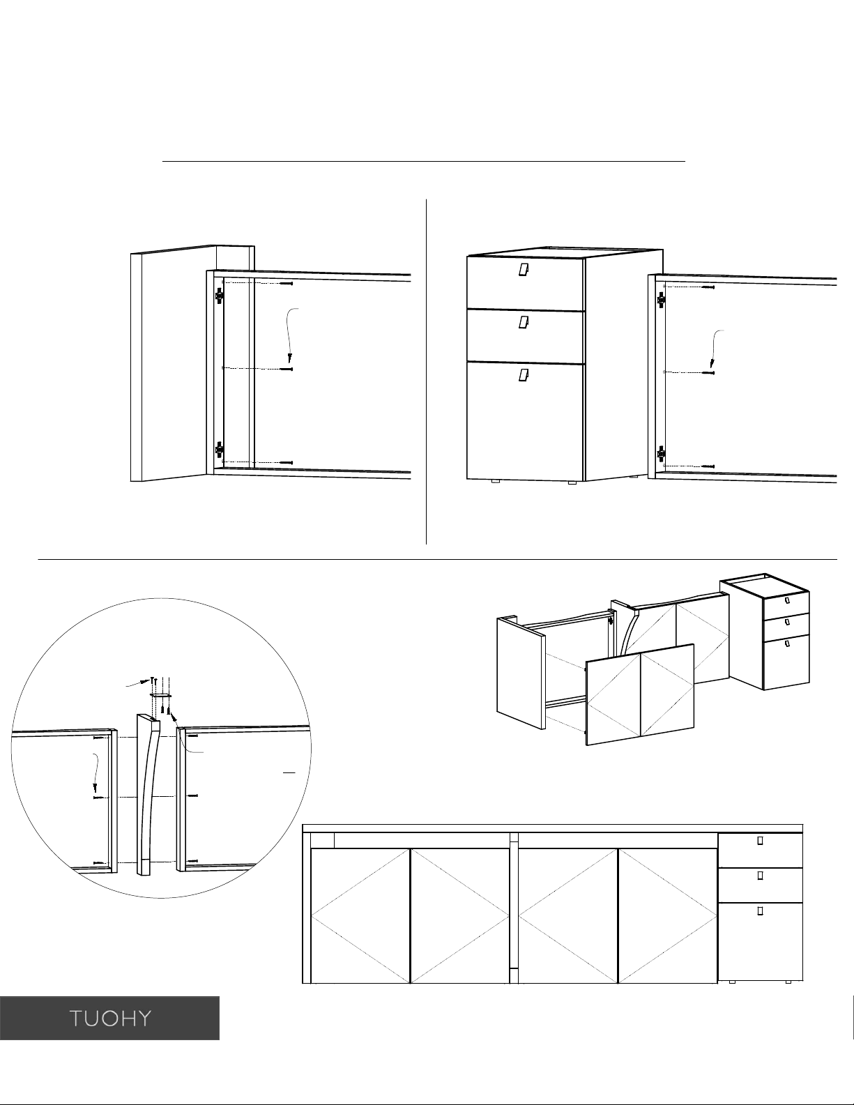
3. Fasten cover panels to secured wall panel
using pre-installed Velcro strips.
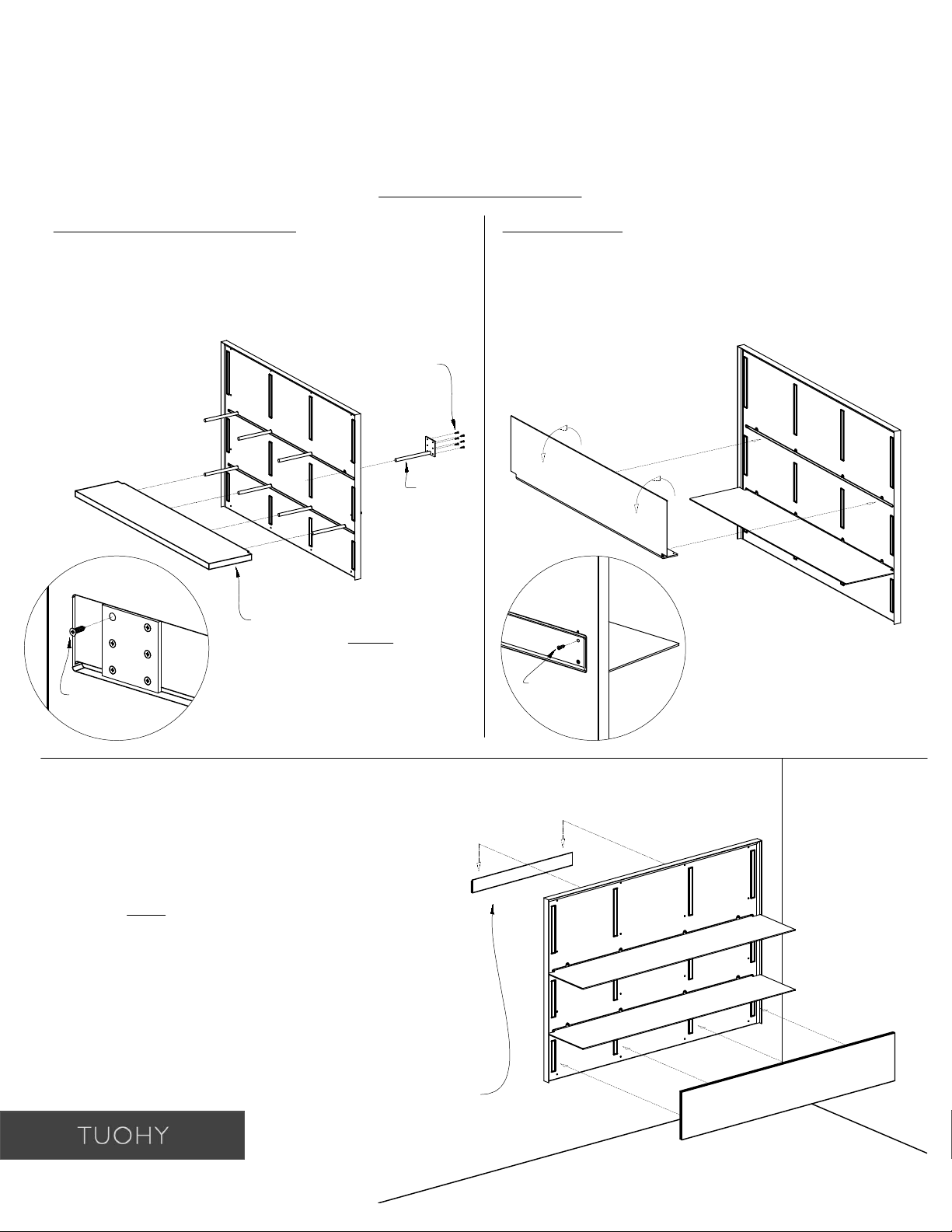
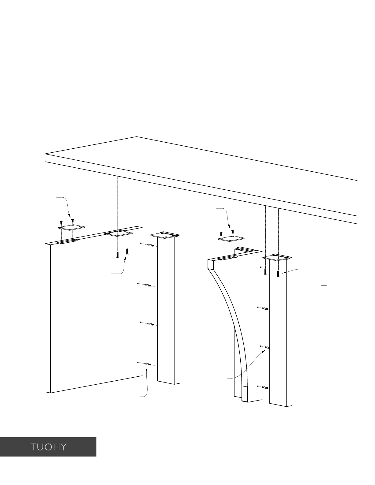
Wood Shelving Support Posts:
1. Insert wood shelving support posts into
allotted holes through back of wall panel.
2. Attach using #8 x 3/4" Flat Head Screws
from back side of wall panel.
French cleat to be installed
as installation aid only.
(Installer responsible for
attachment hardware)
#8 x 3/4"
Flat Head
Screws
Wood
Shelving
Support
Post
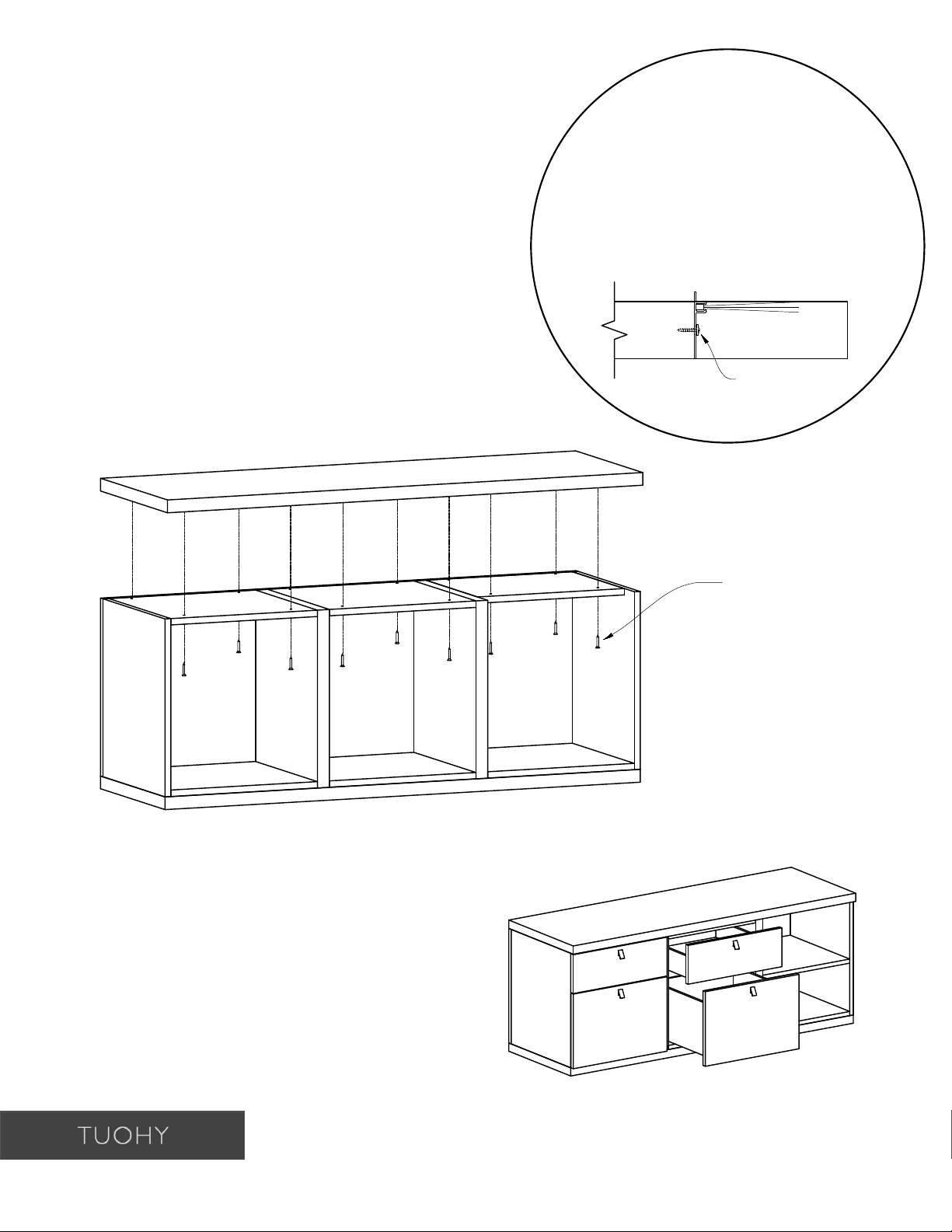
Metal Shelving:
1. Insert metal shelving into slot through front of
wall panel and rotate down at the same time.
2. Attach shelf by screwing #8 x 3/4" Flat Head
Screws through back of shelf into back of wall
panel.
#8 x 3/4"
Flat Head
Screws
(Back View
of Wall
Panel)
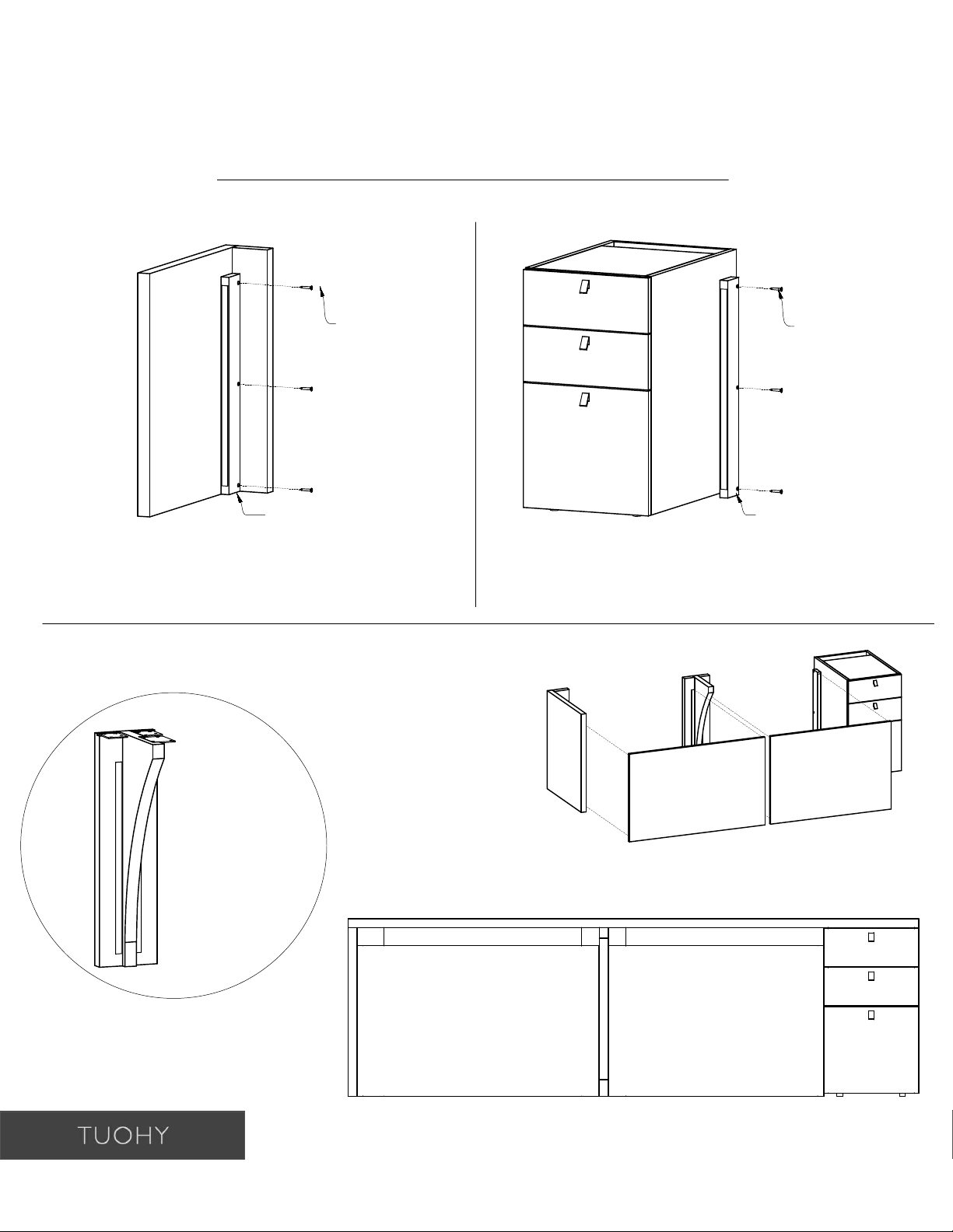
** Slide wood shelves onto
support posts AFTER wall
panel is attached to wall.
(See below for wall panel to
wall attachment).
#8 x 3/4"
Flat Head
Screws
(Back View
of Wall
Panel)