turck IM18-CCM50 Series User manual

Your Global Automation Partner
Instructions for Use
IM18-CCM50…
Cabinet Guard

2Hans Turck GmbH & Co. KG | T +49 208 4952-0 | F +49 208 4952-264 | [email protected] | www.turck.com

V01.01 | 2021/09 3
Contents
1 About These Instructions............................................................................................................... 5
1.1 Target groups................................................................................................................ 5
1.2 Explanation of symbols used ..................................................................................... 5
1.3 Other documents ......................................................................................................... 5
1.4 Feedback about these instructions........................................................................... 5
2 Notes on the Product...................................................................................................................... 6
2.1 Product identification.................................................................................................. 6
2.2 Scope of delivery .......................................................................................................... 6
2.3 Legal requirements......................................................................................................6
2.4 Turck service.................................................................................................................. 6
3 For Your Safety................................................................................................................................. 7
3.1 Intended use.................................................................................................................. 7
3.2 Obvious misuse............................................................................................................. 7
3.3 General safety instructions.........................................................................................7
4 Product Description ........................................................................................................................ 8
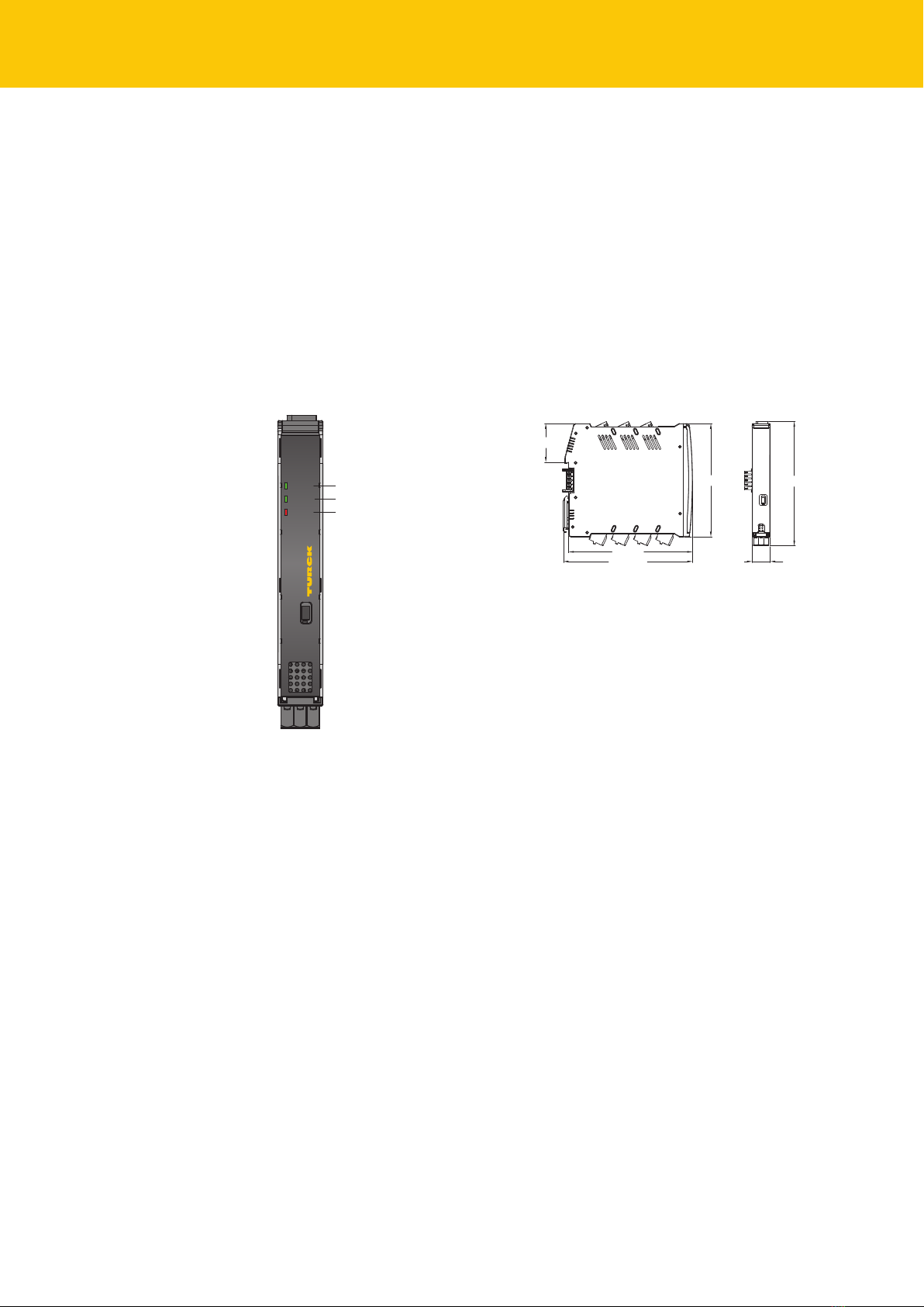
4.1 Device overview ........................................................................................................... 8
4.1.1 Indication elements .....................................................................................................................8
4.2 Properties and features............................................................................................... 8
4.3 Operating principle...................................................................................................... 9
4.4 Functions and operating modes ...............................................................................9
4.4.1 System partitions and recovery system................................................................................9
4.4.2 Ethernet interfaces .......................................................................................................................9
4.4.3 CAN/RS485 interface....................................................................................................................9
4.4.4 GPIOs .................................................................................................................................................9
4.4.5 Analog inputs.............................................................................................................................. 10
4.4.6 Relay................................................................................................................................................ 10
4.4.7 Trusted Platform Module Controller (TPM controller).................................................. 10
4.4.8 USB Host interface..................................................................................................................... 10
5 Installing..........................................................................................................................................11
6 Connection......................................................................................................................................12
6.1 Connecting the device to the higher-level via Ethernet.....................................12
6.2 Connecting an external sensor................................................................................12
6.3 Connecting the power supply .................................................................................12
7 Commissioning ..............................................................................................................................13
7.1 Establishing a network connection ........................................................................13
7.2 Installing user programs ...........................................................................................16
7.3 Example scripts...........................................................................................................17
8 Setting and Parameterization.....................................................................................................19
8.1 User groups – overview.............................................................................................19
8.2 Linux system paths and interfaces – overview.....................................................19
8.3 Analog inputs – available modes and configurations.........................................21
8.4 Analog inputs – available modes and configurations.........................................21
8.5 Relay – available modes............................................................................................21

Contents
4Hans Turck GmbH & Co. KG | T +49 208 4952-0 | F +49 208 4952-264 | [email protected] | www.turck.com
9 Operation ........................................................................................................................................22
9.1 LED indications ...........................................................................................................22
9.1.1 Programming LED indication................................................................................................ 22
9.2 Querying active system partition............................................................................23
9.3 Enable USB device......................................................................................................23
10 Troubleshooting ............................................................................................................................24
10.1 Recovery system.........................................................................................................24
11 Maintenance...................................................................................................................................25
11.1 Carrying out a firmware update via the console..................................................25
11.2 Transferring the firmware update via WinSCP .....................................................26
11.3 Carrying out a firmware update with PuTTY.........................................................30
12 Repair...............................................................................................................................................32
12.1 Returning devices.......................................................................................................32
13 Decommissioning..........................................................................................................................32
14 Disposal ...........................................................................................................................................32
15 Technical Data................................................................................................................................33
16 Turck Subsidiaries - Contact Information .................................................................................35

V01.01 | 2021/09 5
1 About These Instructions
These instructions for use describe the structure, functions and the use of the product and will
help you to operate the product as intended. Read these instructions carefully before using the
product. This is to avoid possible damage to persons, property or the device. Retain the instruc-
tions for future use during the service life of the product. If the product is passed on, pass on
these instructions as well.
1.1 Target groups
These instructions are aimed at qualified personal and must be carefully read by anyone
mounting, commissioning, operating, maintaining, dismantling or disposing of the device.
1.2 Explanation of symbols used
The following symbols are used in these instructions:
DANGER
DANGER indicates a dangerous situation with high risk of death or severe injury if
not avoided.
WARNING
WARNING indicates a dangerous situation with medium risk of death or severe in-
jury if not avoided.
CAUTION
CAUTION indicates a dangerous situation of medium risk which may result in minor
or moderate injury if not avoided.
NOTICE
NOTICE indicates a situation which may lead to property damage if not avoided.
NOTE
NOTE indicates tips, recommendations and useful information on specific actions
and facts. The notes simplify your work and help you to avoid additional work.
uCALL TO ACTION
This symbol denotes actions that the user must carry out.
aRESULTS OF ACTION
This symbol denotes relevant results of actions.
1.3 Other documents
Besides this document the following material can be found on the Internet at www.turck.com:
nData sheet
nQuick Start Guide
nEU Declaration of Conformity (current version)
1.4 Feedback about these instructions
We make every effort to ensure that these instructions are as informative and as clear as pos-
sible. If you have any suggestions for improving the design or if some information is missing in
the document, please send your suggestions to [email protected].

Notes on the Product
6Hans Turck GmbH & Co. KG | T +49 208 4952-0 | F +49 208 4952-264 | [email protected] | www.turck.com
2 Notes on the Product
2.1 Product identification
These instructions apply to the following cabinet guard:
nIM18-CCM50-MTI/24VDC
2.2 Scope of delivery
The scope of delivery includes:
nCabinet guard
nQuick Start Guide
nAdhesive foil (Target) for attaching reflective surfaces
2.3 Legal requirements
The device is subject to the following EC directives:
n2014/30/EU (electromagnetic compatibility)
n2011/65/EU (RoHS Directive)
2.4 Turck service
Turck supports you with your projects, from initial analysis to the commissioning of your applic-
ation. The Turck product database under www.turck.com contains software tools for program-
ming, configuration or commissioning, data sheets and CAD files in numerous export formats.
The contact details of Turck subsidiaries worldwide can be found on p. [}35].

V01.01 | 2021/09 7
3 For Your Safety
The product is designed according to state-of-the-art technology. However, residual risks still
exist. Observe the following warnings and safety notices to prevent damage to persons and
property. Turck accepts no liability for damage caused by failure to observe these warning and
safety notices.
3.1 Intended use
These devices are designed solely for use in industrial areas.
The IM18-CCM… cabinet guard monitors temperature, relative air humidity and the status of
the door in control cabinets.
The devices may only be used as described in these instructions. Any other use is not in accord-
ance with the intended use. Turck accepts no liability for any resulting damage.
3.2 Obvious misuse
nThe device is not a safety component and must not be used for the protection of persons
and property.
3.3 General safety instructions
nThe device only meets the EMC requirements for industrial areas and is not suitable for use
in residential areas.
nThe device may only be assembled, installed, operated, parameterized and maintained by
professionally-trained personnel.
nThe device may only be used in accordance with applicable national and international regu-
lations, standards and laws.
nThe device must only be used in enclosed housing or control cabinets.

Product Description
8Hans Turck GmbH & Co. KG | T +49 208 4952-0 | F +49 208 4952-264 | [email protected] | www.turck.com
4 Product Description
The IM18-CCM50-MTI/24VDC cabinet guard is enclosed in a plastic housing with protection to
IP20 and is provided with three multicolor status LEDs. Two Ethernet ports are provided for
connection to higher-level systems. External sensors can be connected to the device via a CAN/
RS485 port. The Ethernet interfaces and the CAN/RS485 interface are implemented as RJ45
sockets. 3-pin spring-loaded terminals are provided for connecting the power supply, relay out-
put, analog input and GPIOs.
The device is provided with a distance sensor as well as a temperature and humidity sensor.
The Linux Debian operating system is preinstalled on the device. The device functions must be
programmed as required.
4.1 Device overview
RS485/ CAN
ETH0
Pwr
Com
Err
IM18-CCM
10 11 12
7 8 9
4 5 6
1 2 3
Power
Fault
Communication
mm [Inch]
37.5 [1.48]
17.5 [0.69]
120.7 [4.75]
125.7 [4.95]
110 [4.33]
120 [4.72]
Fig.1: Front view Fig.2: Dimensions
4.1.1 Indication elements
The device is provided with a 3-color Pwr LED. Two 2-color user LEDs (Com and Err) are also
provided. The LEDs can be programmed.
4.2 Properties and features
nFreely programmable cabinet guard
nSensors for monitoring humidity, temperature and distance
n3 status LEDs
nLinux operating system (Debian)
n2 Ethernet ports (RJ45 sockets)
n1 CAN/RS485 port (RJ45
n2 GPIO ports
n1 relay
n2 analog inputs
nUSB Host connection
nTPM-IC

V01.01 | 2021/09 9
4.3 Operating principle
The ambient temperature and humidity are monitored by a humidity and temperature sensor
and the door status is monitored by a distance sensor. The device communicates with the
higher-level system via the Ethernet port.
4.4 Functions and operating modes
The device uses integrated sensors to monitor temperature, relative air humidity and the dis-
tance to the control cabinet door. The information can be transferred via Ethernet to higher-
level systems.
The following interfaces are provided on the device:
n2 Ethernet interfaces
nCAN/RS485 interface
n2 GPIOs
n2 analog inputs (configurable as current or voltage input)
nChangeover contact relay
nUSB interface
The operating system provided on the device is the Debian Linux distribution. This enables the
smart preprocessing of data through the integration of tailored programs. The device functions
can be programmed as required.
4.4.1 System partitions and recovery system
The device is provided with two operating system partitions and a recovery system. If one sys-
tem partition is damaged or an update fails, the partitions make it possible to revert to the pre-
vious executable system. A recovery system is started in the event that both system partitions
fail. The recovery system resets the device to the factory settings.
4.4.2 Ethernet interfaces
The device is provided with two Ethernet interfaces ETH0 and ETH1.
The ETH0 interface is a 1 GbE interface in accordance with 1000BASE-T for connecting to
higher-level storage systems or cloud services.
The ETH1 interface is compliant with the 100BASE-TX standard. The transmission speed is
100Mbit/s. The ETH1 enables the device to be connected to an industrial Ethernet network.
The Ethernet interfaces are set for dynamic addressing via DHCP. The following default IP ad-
dresses are also available:
nETH0: 192.168.1.20
nETH1: 192.168.2.20
The max. cable length is 100 m.
4.4.3 CAN/RS485 interface
External devices can be connected to the cabinet guard, e.g. sensors for condition monitoring.
The sensors can be connected for example via Modbus RTU or CAN. The corresponding bus ter-
minals are integrated in the cabinet guard. The CAN/RS485 interface provides a nominal
voltage of 24 VDC for the supply of the external devices.
4.4.4 GPIOs
The GPIOs can be configured separately as digital inputs or outputs. Additional sensors can be
connected to the GPIOs. Simple shell scripts are provided on the system as support for the con-
figuration.

Product Description
10 Hans Turck GmbH & Co. KG | T +49 208 4952-0 | F +49 208 4952-264 | [email protected] | www.turck.com
4.4.5 Analog inputs
The two analog inputs can be configured separately as current inputs (0…35 mA) or voltage in-
puts (0…5 V, 0…10 V or 0…20 V). Additional sensors can be connected to the analog inputs.
Simple shell scripts are provided on the system as support for the configuration.
4.4.6 Relay
The device is provided with a changeover relay for connecting resistive loads. The load capacity
is 48V/0.5A for 100000 switching cycles. Limit value violations can, for example, be forwarded
as switching signals via the relay output. Simple shell scripts are provided on the system as sup-
port for the configuration.
4.4.7 Trusted Platform Module Controller (TPM controller)
The device is provided with a trusted platform module controller (TPM controller) in accord-
ance with the TCG specification (TCG TPM 2.0). The TPM controller allows the possibility of addi-
tional safety functions, e.g. when using the device for license and data protection require-
ments.
4.4.8 USB Host interface
The USB Host interface makes it possible to access the device, e.g. for expanding the memory
with a USB stick. The USB Host interface is implemented as a USB 2.0 high-speed interface. The
USB interface is protected from unauthorized system access by the Linux tool USBGuard. Ac-
cess to the device via the USB interface is only possible for allowed USB devices.

V01.01 | 2021/09 11
5 Installing
NOTICE
Reflective surfaces
Malfunction when monitoring the control cabinet door
Cover glass and highly reflective surfaces on the control cabinet door with matt
adhesive foil (supplied with the device).
The device can be mounted on a DIN rail according to EN 60715 (TH35). The minimum clear-
ance from other devices must be at least 15mm.
RS485/ CAN
ETH0
Pwr
Com
Err
IM18-CCM
10 11 12
7 8 9
4 5 6
1 2 3
RS485/ CAN
ETH0
Pwr
Com
Err
IM18-CCM
10 11 12
7 8 9
4 5 6
1 2 3
RS485/ CAN
ETH0
Pwr
Com
Err
IM18-CCM
10 11 12
7 8 9
4 5 6
1 2 3
≥ 15 mm 15 mm
Fig.3: Minimum clearance
Fasten the device vertically and free-standing on a DIN rail.
Fig.4: DIN rail mounting

Connection
12 Hans Turck GmbH & Co. KG | T +49 208 4952-0 | F +49 208 4952-264 | [email protected] | www.turck.com
6 Connection
NOTICE
Laser class 1 device
Risk of blinding from laser beams
Do not look into the device from the front.
6.1 Connecting the device to the higher-level via Ethernet
The device is provided with two RJ45 sockets for connecting the device to an Ethernet system.
The maximum cable length is 100m. The use of CAT6 S/FTP cables is recommended.
Connect the Ethernet interface via the ETH0 or ETH1 RJ45 port.
6.2 Connecting an external sensor
The device is provided with a CAN/RS485 interface for connecting an external sensor. The CAN/
RS485 interface is implemented as an RJ45 socket. The maximum cable length is 30m.
Connect the external sensor to the device via the CAN/RS485 interface.
87654321
v1 = CAN_H
2 = CAN_L
3 = +
4 = A (RS485)
5 = B (RS485)
6 = +
7 = –
8 = –
Fig.5: Pin layout of the CAN/RS485 interface
6.3 Connecting the power supply
The power supply can be connected using spring-loaded terminals. The removable terminal
blocks are coded.
Only use cables (rigid or flexible) with a cross section of 0.2…2.5 mm².
When using stranded wire: Secure the wire ends with ferrules.
Prise open the spring-loaded terminals using a screwdriver.
Insert the stripped cable ends into the guides of the spring-loaded terminals.
Remove the screwdriver.
0.2…2.5 mm2
(24…13 AWG)
7 [0.28]
2
1
Fig.6: Connecting the power supply via spring-loaded terminals

V01.01 | 2021/09 13
7 Commissioning
The device is operational automatically once the cables are connected and the power supply is
switched on. All LEDs are lit in several colors during the boot procedure. After the boot proced-
ure has been successfully completed, the Pwr LED flashes green at a frequency of 2Hz.
The Linux operating system enables the device functions to be programmed or scripts to be
imported. An SSH connection can be established once the device is connected to the network.
Additional software tools (e.g. PuTTY) are required to access the device via the console. The IP
address depends on the selected connection. The user sshu also has the possibility to use sudo
options.
Command example
$ This_is_a_console command /example/path
> Example output
Example content of a file
7.1 Establishing a network connection
After a physical connection has been established, a ping command can be used to check
whether the device can be reached. An SSH connection to the device can then also be set up
using an SSH or SFTP client software (e.g. PuTTY, WinSCP or similar).
NOTICE
Insufficiently secured devices
Unauthorized access to sensitive data
Change the password after the first login. Turck recommends the use of a secure
password.
Establish a network connection via the ETH0 or ETH1 interface with the following set-
tings:
Setting Description
Connection type SSH
User sshu
Password P@ssw0rd12ssh!
Port 1522
Default hostname ccm-<SERIAL NUMBER> (example: ccm-0407361310002001)
ETH0 IP address 192.168.1.20
ETH1 IP address 192.168.2.20

Commissioning
14 Hans Turck GmbH & Co. KG | T +49 208 4952-0 | F +49 208 4952-264 | [email protected] | www.turck.com
Fig.7: Access via PuTTY
After the login, the folder /home in the working directory becomes active with restricted write
access rights. Write and read operations are enabled in the subfolder /home/temp.

V01.01 | 2021/09 15
Fig.8: Login output

Commissioning
16 Hans Turck GmbH & Co. KG | T +49 208 4952-0 | F +49 208 4952-264 | [email protected] | www.turck.com
7.2 Installing user programs
Additional programs can be installed via the apt or apt-get package manager in Linux by enter-
ing the required package [PACKAGE]. Installation in the /opt partition is recommended in or-
der to achieve a separation between the operating system and user software.
Install the package:
$ sudo apt update
$ sudo apt install [PACKAGE]
The device has the following partitions:
Mount point Size Contents
/ 1.4 GB System partition
/var 256 MB Variable and temporary data of the system
/opt 1.6 GB User programs, if necessary user data
/home 768 MB /home folder for all users
/home/temp 1 GB Subfolder in the home directory, to which special au-
thorizations can be issued
/home/settings 64 MB Folder for settings and scripts for all operating systems
/home/factory 16 MB Folder for manufacturer information

V01.01 | 2021/09 17
7.3 Example scripts
The folder /home/scripts contains different scripts for operating the interfaces and system
functions. The scripts are examples of how the functions can be integrated in user-defined user
programs.
Fig.9: Script directory in the /home folder
If a script is called without transfer parameters, a help text appears that shows the relevant
parameters.
Fig.10: Output of the help texts for scripts
The following table is an overview of the scripts present in the IM18-CCM:
Function Script Option Description
Ambient temperat-
ure and air humid-
ity
ambient_read.sh temp Measurement and display of the
ambient temperature
hum Measurement and display of the
ambient air humidity
all Measurement and display of temperat-
ure and air humidity
help Display help text
Distance sensor distance_calibrate.sh [values] Calibration of distance sensor
help Display help text
distance_read.sh [samples] Measurement and display of
distance
help Display help text

Commissioning
18 Hans Turck GmbH & Co. KG | T +49 208 4952-0 | F +49 208 4952-264 | [email protected] | www.turck.com
Function Script Option Description
System system_check.sh ntc1 Measurement and display of
the temperature of NTC1 (temperature
dependent resistor)
ntc2 Measurement and display of
the temperature of NTC2 (temperature
dependent resistor)
supply Measurement and display of the
power supply
all Measurement and display of
all options
help Display help text
Analog inputs analog_init.sh [channel]
[range]
Configure input range [range] for
one channel [channel]
[range]: 5V, 10V, 20V or 20mA
[channel]: 1 or 2
help Display help text
analog_read.sh 1 Measurement of the analog value on
channel 1
2Measurement of the analog value on
channel 2
help Display help text
GPIO gpio_init.sh [pin] in Configure GPIO [pin] as an input
[pin]: 1 or 2
[pin] out [level] Configure GPIO [pin] as output and
define level [level]
[pin]: 1 or 2
[level]: low or high
gpio_read.sh [pin] Read level on GPIO [pin]
help Display help text
gpio_write.sh [pin] [level] Set level [level] on GPIO [pin]
help Display help text
Relay relay_read.sh status Read and display status of the relay
help Display help text
relay_write.sh inactive Set relay in opened state:
CO-NC: closed
CO-NO: opened
active Set relay in closed state:
CO-NC: opened
CO-NO: closed
help Display help text
Other scripts must be programmed or imported.

V01.01 | 2021/09 19
8 Setting and Parameterization
The Linux Debian operating system enables the device functions to be parameterized for the
specific application.
8.1 User groups – overview
The different user groups are defined in the operating system of the device in order to assign
application-specific access rights.
Name Description Assigned periphery
led Enables access to the LEDs All LEDs
gpio Enables access to the digital GPIOs and
the relay
Scripts gpio*.sh and relay*.sh and corres-
ponding periphery
analogin Enables access to the analog inputs Scripts analog*.sh and corresponding
periphery
i2c Enables access to the distance sensor Scripts distance*.sh, Tool vl53l1_distance
and corresponding periphery
rs485 Enables access to the RS485 interface
home User group for shared /home directory
syscheck Enables access to the system internal
sensors
Script system_check.sh and correspond-
ing periphery
8.2 Linux system paths and interfaces – overview
The following table shows an overview of the most important system devices and system paths
as well as interfaces under Linux. Refer to the example scripts at /home/scripts/ for instructions
for use.
device/system path and
interface
eth0 Ethernet interface
eth1 Ethernet interface
usb1 USB Host interface
/dev/rtc0 Microprocessor internal RTC
/dev/rtc1 Buffered hardware RTC
/dev/tpm0 TPM-IC
/dev/ttyO1 RS485 interface
can0 CAN interface
/sys/class/hwmon/hw-
mon0/
sysfs path for sht3x driver for temperature and air humidity sensor
vl53l1_distance Tool for configuring and reading the distance sensor
/sys/bus/iio/devices/
iio:device0/
sysfs path for microprocessor internal ADC (12-bit)
/sys/class/gpio sysfs path for GPIO of the microprocessor internal (µP)
/sys/class/leds/ sysfs path for LED
in_voltage0_raw Analog input AIN1: ADC channel
gpio70 Analog input AIN1: Switching from voltage measurement (low) or cur-
rent measurement (high)
gpio75 Analog input AIN1: Voltage measurement range switching 0…5V
(low) or 0…10V (high)

Setting
20 Hans Turck GmbH & Co. KG | T +49 208 4952-0 | F +49 208 4952-264 | [email protected] | www.turck.com
device/system path and
interface
gpio76 Analog input AIN1: Voltage measurement range switching 0…5V
(low) or 0…20V (high)
in_voltage1_raw Analog input AIN2: ADC channel
gpio71 Analog input AIN2: Switching from voltage measurement (low) or cur-
rent measurement (high)
gpio77 Analog input AIN2: Voltage measurement range switching 0…5V
(low) or 0…10V (high)
gpio78 Analog input AIN2: Voltage measurement range switching 0…5V
(low) or 0…20V (high)
gpio47 Digital output GPIO1: Switching between input (low) or output (high)
gpio61 Digital output GPIO1: Set level when configured as output: low or high
gpio66 Digital output GPIO1: Read level at GPIO1 (irrespective of configura-
tion)
gpio103 Digital output GPIO1: Diagnostic signal: low (output inactive or error)
or high (output active, no error)
gpio67 Digital output GPIO2: Switching between input (low) or output (high)
gpio68 Digital output GPIO2: Set level when configured as output: low or high
gpio69 Digital output GPIO2: Read level at GPIO2 (irrespective of configura-
tion)
gpio104 Digital output GPIO2: Diagnostic signal: low (output inactive or error)
or high (output active, no error)
gpio23 Relay: Switching between inactive NC (low) and active NO (high)
in_voltage2_raw System internal: internal measurement of the operating voltage
in_voltage3_raw System internal: Temperature sensor NTC1
in_voltage4_raw System internal: Temperature sensor NTC2
This manual suits for next models
1
Table of contents
Other turck Safety Equipment manuals
Popular Safety Equipment manuals by other brands

ABS
ABS ABS-Lock III-BE installation manual

Tractel
Tractel FABA 514408 Operating and maintenance instructions

Tractel
Tractel TO13 Instructions for use

provita
provita sens07vest user manual

Lidl Service
Lidl Service HG04131A Operation and safety notes

Climbing Technology
Climbing Technology Sparrow 2D646 manual

3M
3M Peltor X Series manual

ROCK
ROCK RETRAC PS-20 user guide

HABERKORN
HABERKORN euroline Tree Austria 3.2 INSTRUCTIONS FOR USE AND TEST MANUAL

Mustang Survival
Mustang Survival MD2020 owner's manual

Sperian
Sperian Miller EN 360 Instructions for use

Vetter
Vetter VCB C.Tec Translation of the original operating instructions