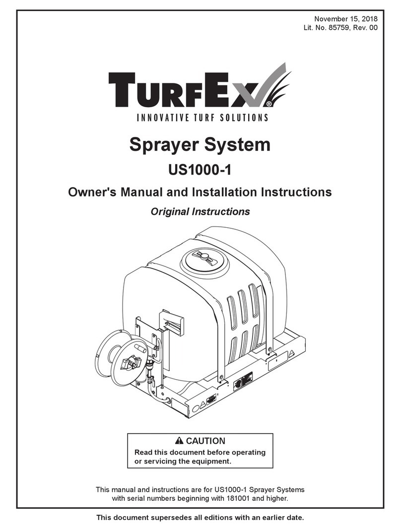
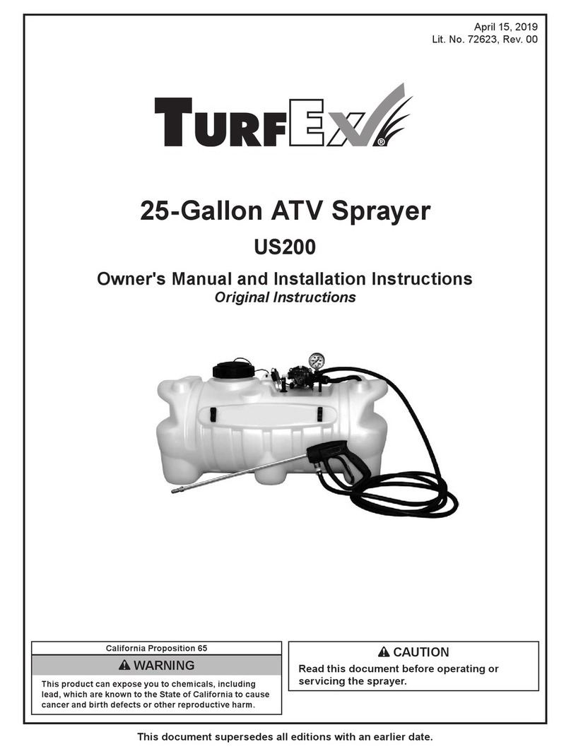
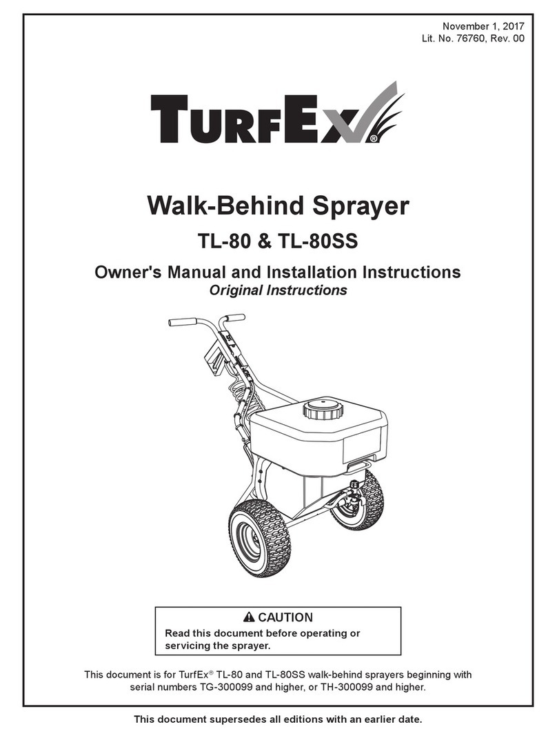
TurfEx US-500 Owner's manual

Owner / Operator’s Manual
The Commercial Turf Choice
This Manual Must Be Read Before Operating The Equipment
R
US-500
US-1000
SPRAYERS
September 1,2018
Lit. No. 76596, Rev. 00

Table of Contents
Introduction . . . . . . . . . . . . . . . . . . . . . . . . . . . . . . . . . . . . . . . . . . . . . . . . . . . . . . . . . . . . . . . . . . . . . . . . . . . . . . . . . . . . . . . . . . . 3
General Information and Registration . . . . . . . . . . . . . . . . . . . . . . . . . . . . . . . . . . . . . . . . . . . . . . . . . . . . . . . . . . . . . . . . . . . . . . . . . . . .
4
Safety Information . . . . . . . . . . . . . . . . . . . . . . . . . . . . . . . . . . . . . . . . . . . . . . . . . . . . . . . . . . . . . . . . . . . . . . . . . . . . . . . . . . . . . . .
5-9
System Sub Assemblies . . . . . . . . . . . . . . . . . . . . . . . . . . . . . . . . . . . . . . . . . . . . . . . . . . . . . . . . . . . . . . . . . . . . . . . . . . . . . . . . . . . . . . . . . 10
Tank Exploded View . . . . . . . . . . . . . . . . . . . . . . . . . . . . . . . . . . . . . . . . . . . . . . . . . . . . . . . . . . . . . . . . . . . . . . . . . . . . . . . . . . . . . . 11
Reel Exploded View . . . . . . . . . . . . . . . . . . . . . . . . . . . . . . . . . . . . . . . . . . . . . . . . . . . . . . . . . . . . . . . . . . . . . . . . . . . . . . . . . . . . . . . . . . . 13
Tank Assembly View . . . . . . . . . . . . . . . . . . . . . . . . . . . . . . . . . . . . . . . . . . . . . . . . . . . . . . . . . . . . . . . . . . . . . .. . . . . . . . . . . . . . . . . . . . 12
R
Reel Assembly View . . . . . . . . . . . . . . . . . . . . . . . . . . . . . . . . . . . . . . . . . . . . . . . . . . . . . . . . . . . . . . . . . . . . . . . . . . . . . . . . . . . . . . . . . . .
14
Pump Exploded View . . . . . . . . . . . . . . . . . . . . . . . . . . . . . . . . . . . . . . . . . . . . . . . . . . . . . . . . . . . . . . . . . . . . . . . . . . . . . . . . . . . . . . . . . 15
Pump Assembly View . . . . . . . . . . . . . . . . . . . . . . . . . . . . . . . . . . . . . . . . . . . . . . . . . . . . . . . . . . . . . . . . . . . . . . . . . . . . . . . . . . . . . . . .16
Frame Exploded View . . . . . . . . . . . . . . . . . . . . . . . . . . . . . . . . . . . . . . . . . . . . . . . . . . . . . . . . . . . . . . . . . . . . . . . . . . . . . . . . . . . . . . . . . 17
Frame Assembly View . . . . . . . . . . . . . . . . . . . . . . . . . . . . . . . . . . . . . . . . . . . . . . . . . . . . . . . . . . . . . . . . . . . . . . . . . . . . . . . . . . . . . . . . 18
Electrical Assembly View. . . . . . . . . . . . . . . . . . . . . . . . . . . . . . . . . . . . . . . . . . . . . . . . . . . . . . . . . . . . . . . . . . . . . . . . . . . . . . . . . . . . . . . 19
Electrical Diagram and Instructions . . . . . . . . . . . . . . . . . . . . . . . . . . . . . . . . . . . . . . . . . . . . . . . . . . . . . . . . . . . . . . . . . . . . . . . . . . . . 20
Lit. No. 76596, Rev. 00 September 1,2018
2

Introduction
This manual has been designed for your help.It will assist you and instruct you on the proper set-up,installation and use of
this sprayer product.
Refer to the table of contents for an outline of this manual.
Werequire that you read and understand the contents of this manual completely (especially all safety information) before
attempting any procedure contained herein.
THIS SIGN SHOULD ALERT YOU:
The Society of Automotive Engineers has adopted this SAFETY ALERT SYMBOL to pinpoint characteristics that,
if NOT carefully followed, can create a safety hazard. When you see this symbol in this manual or on the
machine itself, BE ALERT! Your personal safety and the safety of others is involved
.
Dened below are the SAFETY ALERT messages and how they will appear in this manual:
(RED)
Information that, if not carefully followed,
can cause death!
(ORANGE)
Information that, if not carefully followed,
can cause serious personal injury or death!
(YELLOW)
Information that, if not carefully followed,
can cause minor injury or damage to equipment.
R
Lit. No. 76596, Rev. 00 September 1,2018
3

General Information
SER. NO.______________________
TRYNEX INTERNATIONAL
531 Ajax Drive
Madison Heights, MI 48071-2429
R
Registration
Record the following information in this manual for quick reference.
Sprayer Model Number________________________________________________________________________________________
Sprayer Serial Number ________________________________________________________________________________________
Date of Purchase __________________________________________________________________________________________
Dealer Where Purchased ______________________________________________________________________________________
When ordering parts, the above information is necessary. This will help to insure
that you receive the correct parts.
At the right is a diagram of the ID tag. Please ll out the warranty card with all the
necessary information to validate it. This will also give us a record so that any
safety or service information may be communicated to you.
R
CONGRATULATIONS!
The TurfEx product you have purchased is part of a full line of professional-duty equipment for the turf
and landscapingcaping professional. TurfEx provides an innovative
solution to do the job quickly
eectively.
SIMPLICITY – Fewer moving partsmeans minimal maintenance.
RELIABILITY – High impact linear low density polyethylene hoppers and tanks, state-of-the-art electronics, powder
coated frames, patented 12-volt motor/transmissions, and other high quality components make
TurfEx products durable and dependable.
VERSITILITY – Multi-use capabilities allows use of a variety of materials and applications.
WARRANTY – ONE YEAR from the date of purchase.
TurfEx products cover your spreading, storage, sweeping, grooming and spraying
needs – all from a single source . . . The Commercial Turf Choice.
Lit. No. 76596, Rev. 00
4
September 1,2018

Safety
R
Before attempting any procedure in this book, these safety instructions must be read and understood by all workers who
have any part in the preparation or use of this equipment.
For your safety warning and information decals have been placed on this product to remind the operator of safety precautions.
If anything happens to mark or destroy the decals, please request new ones from Trynex, International.
Remember most accidents are preventable and caused by human error. Exercising of care and
precautions must be observed to prevent the possibility of injury to operator or others!
Never operate equipment when under the inuence of alcohol, drugs, or medication that might
alter your judgment and/or reaction time.
Always wear safety glasses with side shields when working metal against metal. Failure to do this
could result in serious injury to the eyes or other parts of the body.
Always wear safety glasses with side shields when working metal against metal. Failure to do this
could result in serious injury to the eyes or other parts of the body.
Never allow children to operate or climb on equipment.
Never weld or grind on equipment without having a re extinguisher available.
Always check areasto be swept to be sure no hazardous conditions or substances are in the area.
Always inspect unit for defects:broken,worn or bent parts,weakened areas on broom or mount.
Always shut o vehicle and power source before attempting to attach or detach or service broom unit.
Be sure vehicle/power source is properly braked or chocked.
Always make sure personnel are clear of areas of danger when using equipment.
Always keep hands, feet, and clothing away from power-driven parts.
Remember it is the owner’s responsibility to communicate information on safe usage and proper
maintenance of all equipment.
Lit. No. 76596, Rev. 00
5
September 1,2018

Safety
R
PREPARATION
Check area for foreign objects or obstacles that could cause personal injury. Keep other
persons, children or animals out of the area to be treated.
OPERATION
Recognize company and government regulations and follow safety recommendations of both.
to ignore this could mean serious injury or even death of operator or others.
Safety goggels must be worn by operator at all times to prevent chemicals from injuring eyes.
Be aware of your surroundings when operating motorized vehicles while spraying.
SERVICE
When service is necessary, perform it in a protected area. Do not use power tools in rain or
snow because of danger of electrical shock or injury. Keep area well lighted, Use proper tools
and keep service area clean to help avoid accidents.
Lit. No. 76596, Rev. 00
6
September 1,2018

Operational Safety Information
R
Summary of Important Safety Information
Chemical accident procedures
Immediate response is necessary in the event of sprayer leaks, bodily chemical contact, poisoning, or
spills. See instructions below:
Sprayer leak If the sprayer develops a leak, immediately stop spraying. Turn o power to the sprayer
and follow directions below, as applicable.
Bodily chemical
contact
Personal contamination can occur when chemicals splash, spill, or spray directly
onto a person.
1. Immediately follow First Aid instructions on chemical label.
General procedures can include:
a) Eyes – immediately ush with water.
b) Skin – wash all contaminated skin surfaces with soap and water.
c) Clothing – remove contaminated clothing. Dispose of heavily contaminated
clothing per chemical label instructions.
2. Seek medical advice if instructed on the label or the victim experiences symptoms of
harmful eects. Bring the chemical label for reference.
Poisoning by
ingestion or
inhalation
In case of poisoning from ingestion or inhalation
:
If the victim has collapsed or is not breathing, call 911. Otherwise:
1. If you are the victim, immediately seek assistance fromnearby personnel because you
may become incapacitated.
2. Immediately follow rst aid instructions on chemical label.
3. Call a poison controlcenter for furtheradvice. In the U.S., call 1-800-222-1222. Have
the chemical label available for reference.
Chemical spills
Chemical spills must quicklybe contained and properly cleaned up.
Refer to the chemical label for any specic clean-up instructions.
General procedures include:
1. Controlling the spill by stopping the source of the spill.
2. Containing the spill so that it does not spread and get into water sources.
3. Cleaning up the spill immediately.
4. Seeking additional advice from:
-Chemical manufacturer.See chemical label for contact information.
-State pesticide regulatory agency. In the U.S., call the National Pesticide Info. Ctr.
at 800-858-7378 for assistance in contacting your state’s agency.
Lit. No. 76596, Rev. 00
7
September 1,2018

Operational Safety Information
R
Summary of Important Safety Information
LISTED BELOW is a summary of safety information of particular importance.
See individual sections of this owner’s manual for more details.
DURING ASSEMBLY
CHECK and TEST completed assembly as directed in this manual. Serious injury could result from chemical
leaks if sprayer is improperly assembled.
DURING OPERATION
READ and FOLLOW each chemical label’s instructions and warnings.
AVOID inhaling, ingesting, or coming into contact with any chemicals.
KNOW applicable licensing and regulatory requirementsfor the chemical you plan to use.
KNOW emergency procedures before handling chemicals. Carefully review “Chemical Accident
Procedures” listed below and later in this manual. Also see First Aid instructions on the chemical label.
WEAR protective clothing, eye protection, and chemical resistant gloves when lling, using and
cleaning the sprayer. Wear additional protective gear, such as facemask or apron, as recommended on the
chemical label.
EXERCISE EXTRA CAUTION around children and pets. Pesticides are especially toxic to them. Keep
sprayer and spray materials away from them at all times.
DO NOT MIX OR POUR chemicals in an enclosed, unventilated area.
DO NOT USE ammable or corrosive chemicals in the sprayer.
FLUSH the sprayer before switching chemicals in order to prevent dangerous chemical interactions.
STORE pesticides in a correctly labeled container and in a secure location.
MONITOR the health of operators frequently exposed to pesticides, as recommended by the chemical
label or local/federal regulations.
BEFORE SPRAYING
INSPECT and PREPARE sprayer before each use as directed in this manual.
FOLLOW INSTRUCTIONS for SAFELY FUELING the engine. Gasoline is ammable and can explode.
Always use caution when handling gasoline.
DO NOT START sprayer until ready to spray in order to avoid unintentional spray release.
WEAR ADDITIONAL PERSONAL PROTECTIVE EQUIPMENT if you will be spraying overhead.
You will be exposed to much more chemical fallout in these applications. Wear chemical resistant head and neck
protection, full face mask or halfface mask with sealed goggles, and consider using a respirator.
DO NOT SPRAY when wind speed exceeds 4 MPH in order to minimize spray drift.
KEEP sprayer and spray materials away from children/pets. Pesticides can be especially toxic to children
and animals.
DO NOTALLOW anyone younger than 16 to operatesprayer since pesticides are especially toxic to children.
DO NOT MODIFY SPRAYER DESIGN
Lit. No. 76596, Rev. 00
8
September 1,2018

Operational Safety Information
Summary of Important Safety Information
During Spraying
•DO NOT OVERAPPLY pesticide. Apply atrate recommended by chemical manufacturer. Excess
pesticide can be dangerous to humans/animals, damage desirable plants, and contaminate soil and water
sources.
•DO NOT EAT, DRINK, SMOKE, RUB YOUR EYES, or TOUCH YOUR BARE SKIN while
handling chemicals and spraying .
•NEVER POINT THE SPRAY GUN at people or animals.
•DO NOT SPRAY near open ames or sources of heat.
•ALWAYS HOLD THE SPRAY GUN FIRMLY when using it to spray at higher pressures in order to
prevent gun from whipping. Keep good footing and balanceatall times.
•EXERCISE EXTRA CAUTION when spraying near areas accessible to children and pets.
•CLEAN up spills immediately per instructions on the chemical label.
•TURN OFF vehicle and set brake or block wheels, TURN OFF sprayer, and RELIEVE system
pressure before leaving sprayer unattended.
•SEE Troubleshooting section of this manual before attempting any repairs. Wear personal protective
equipment and follow safety instructions.
After Spraying
CLEAN sprayer immediately after use according to the directions provided in this manual.
DECONTAMINATE yourself after you are done spraying and have cleaned the sprayer. Wash all exposed
areas of the body with soap and water, and remove and launder clothing.
DISPOSE OF or STORE remaining chemicals in secure storage with correctly marked container.
Transporting Safety
READ safety instructions in your vehicle manualwith regard to carrying heavy cargo loads.
DO NOT ALLOW drivers younger than 16 to drive the vehicle with the lled sprayer attached.
MAKE SURE SPRAYER IS SECURELY ATTACHED to vehicle.
EXERCISE CAUTION in vehicle handling when driving with lled sprayer to avoid loss of control or
rollover.
oKeep speed to a minimum so you can maintain control. Reduce speed prior to turns.
oAllow for more distance to stop .
oAvoid any sudden steering maneuvers, starts, or stops that could create liquid sloshing in the sprayer
and instability.
SLOW DOWN and EXERCISE EXTRA CAUTION on sloped or uneven terrain. Pick the most level
route possible across elds--drive up and down slopes when necessary, rather than across. Use a vehicle
equipped with a roll over protection system (ROPS) if you will be working on non-level terrain.
BE AWARE that visibility may be reduced when making turns or backing up.
DO NOTRIDE or TRANSPORT cargo on thesprayer.
TURN OFF both sprayer and vehicle, and SET BRAKES before leaving unattended.
Lit. No. 76596, Rev. 00
9
R
September 1,2018

US-500 / US-1000
System Sub-Assemblies
Key
Reel Assembly
Frame Assembly
Pump & Hose Assembly With Agitation
Tank Assembly
Description
Electrical Assembly
Revised design
as of 04/04/2011
NOTE: Hose reel
assembly has rotated
180 degrees as of 04/04/2011
Note: New for 04/2011 Production
Lit. No. 76596, Rev. 00
10
R
September 1,2018

US-500 / US-1000
TANK EXPLODED VIEW
R
Agitation port added
04/05/2011
Lit. No. 76596, Rev. 00
11
September 1,2018

US-500 / US-1000
Tank Assembly View
R
Key
T 20300
US-1000 TANK (100 GAL.)
US-500 TANK (50 GAL.)
TANK LID
TANK STRAINER
BULKHEAD FITTING ASSY
US-500 TANK STRAP
US-1000 TANK STRAP
90 DEGREE FITTING
T 20309
T 20323
T 20324
D 6917
T 20304
T 20308
T 20313
1
1
1
1
1
2
2
1
Part No. Description Qty.
Lit. No. 76596, Rev. 00
12
September 1,2018

US-500 / US-1000
Reel exploded View
NOTE: Hose reel assembly has rotated 180 degrees as 04/05/2011
in order to accomodate new agitation system.
Lit. No. 76596, Rev. 00
13
R
September 1,2018

US-500 / US-1000
Reel Assembly View
Key
D 5706
Reel Stop Bracket
5/8-16 Serrated Flange Nut
Hose Reel Tube Weldment
5/16-18 x 1 Hex Head
Hose
Poly Hose Reel
Hose Barb Fitting
Elbow
Swivel Fitting
Retainer Ring
Retainer Washer
Spray Gun
5/16-18 Nylock Nut
T 20311
T 20310
D 6166
T 20306
T 20305
T 20331
T 20330
T 20316
T 20319
T 20320
T 20307
D 6138
4
1
1
4
1
1
1
1
1
1
1
1
1
Part No. Description Qty.
NOTE: Hose reel assembly has rotated 180 degrees as 04/05/2011
in order to accomodate new agitation system.
Lit. No. 76596, Rev. 00
14
R
September 1,2018

US-500 / US-1000
Pump Exploded View
To Tank Lower Outlet
To Hose Reel Input
NOTE: Assembly has changed as of
04/05/2011 to include the new
agitation system. See page 16for
additional part call outs.
Lit. No. 76596, Rev. 00
15
R
September 1,2018

US-500 / US-1000
Pump Assembly View
R
Key
D 5267
Small Hose Clamp
Filter Assembly
Filter Hose Segment
#10 SAE Washer
#10-32 x 1-1/4 Pan Head
Tank Hose Segment (30”)
#10 Hex Nut
Reel Supply Hose Segment
Hose Reel Input Elbow
12 VDC Pump
Large Hose Clamp
T 20327
T 20329
T 20318
D 6157
D 6529
D6989
D 6158
T 20326
T 20314
D 5265
T 20325
1
4
1
1
8
4
1
4
1
1
1
2
Part No. Description Qty.
Current assembly through 03/31/2011
1
2
3
12
11
13
10
7
5
9
6
4
8
Key
D 5213
1/2” To 3/8” Straight Barb
Gauge
3/8” Hose Crimp Clamp
Reducing Bushing 1/2” x 1/4”
Adapter 5/8” QA x 1/2” Male
Pipe Cross 1/2”
Pipe Adapter
Garden Hose Clamp
1/2” Close Nipple
Throttle Valve 1/2”
90 Degree Poly Nozzle Body
Pipe Tee 1/2”
D 6929
T 20325
D 5353
D 5356
D 5354
D 5357
T 20131
D 6920
D 5352
D 6951
D 5355
1
1
3
1
1
1
1
1
1
1
1
1
Part No. Description Qty.
New agitation circuit 04/01/2011 to present
Hose Barb 1/2” Male x 3/8” 90
D 5377 1
Lit. No. 76596, Rev. 00
16
September 1,2018

US-500 / US-1000
Frame Exploded View
R
Lit. No. 76596, Rev. 00
17
September 1,2018

US-500 / US-1000
Frame Assembly View
R
Key
T 20302
3/8-16 Serrated Flange Nut
Hose Reel Mountin Bracket
US-500 Main Frame
US-1000 Main Frame
D 6584
T 20301
T 20303
1
2
1
1
Part No. Description Qty.
Lit. No. 76596, Rev. 00
18
September 1,2018

US-500 / US-1000
Electrical Assembly View
R
Lit. No. 76596, Rev. 00
19
September 1,2018

US-500 / US-1000
R
Step 1: First, install switch at desired location. This will determine what the
proper wire length should be.
Step 2: Run spreader/vehicle harness from the rear of vehicle to switch area.
Remove approx. 3'' of the black outer jacket exposing two single leads (red and
black), strip a 1/4'' o each lead. Crimp 1/4'' female connector on red lead and
crimp the butt connector to the black lead. Place the female spade/red wire to
the on/o switch and leave the black wire for the next step.
Step 3: Route the power harness from the battery to the switch; this will
determine proper length to cut wires. Repeat step #2 regarding cable jacketing
and connection points to the switch and butt connector.
Step 4: Install an inline 30 amp. fuse on the positive (red) lead from the battery
to the switch. Locate an easily accessible place, out of the elements, for the
fuse and remove approx. 3'' of the black outer jacket exposing two single leads
(red and black). Cut the red lead in half and strip a 1/4'' o each lead. Insert
into the fuse connector and crimp. Insert 30 amp. blade fuse into connector.
Step 5: At the battery end of the power harness, remove 8'' of the black outer jacket exposing two single leads
(red and black) strip 1/4” off each lead. Crimp a 3/8'' lug terminal to each lead and attach the red lead to the positive
side of the battery and the black lead to the negative side of the battery.
Step 6: Install rubber weatherproof boot on switch before finishing installation.
Electrical Diagram and Instructions
Key
D 6184
Butt Connector
On/O Switch
Dielctric Grease
20’ Vehicle Harness
10’ Battery Harness
Rubber Switch Boot
Spreader Splice Cord - 10”
Harness Splice Cord - 10”
Motor 12 Volt DC
30 Amp Fuse
Fuse Holder
Ring Terminal
Spade Connector
D 6234
D 6344
D 6403
D 6404
D 6406
D 6407
D 6408
D 6410
D 6424
D 6425
D 7105
D 7106
30 AMP
(+) Pos.Red
(–) Neg. Black
(–) Neg. Black
(+) Pos.Red
12 VOLT
BATTERY
1
1
1
1
1
1
1
1
1
1
1
2
2
Part No. Description Qty.
Lit. No. 76596, Rev. 00
20
September 1,2018
This manual suits for next models
1
Table of contents
Other TurfEx Paint Sprayer manuals