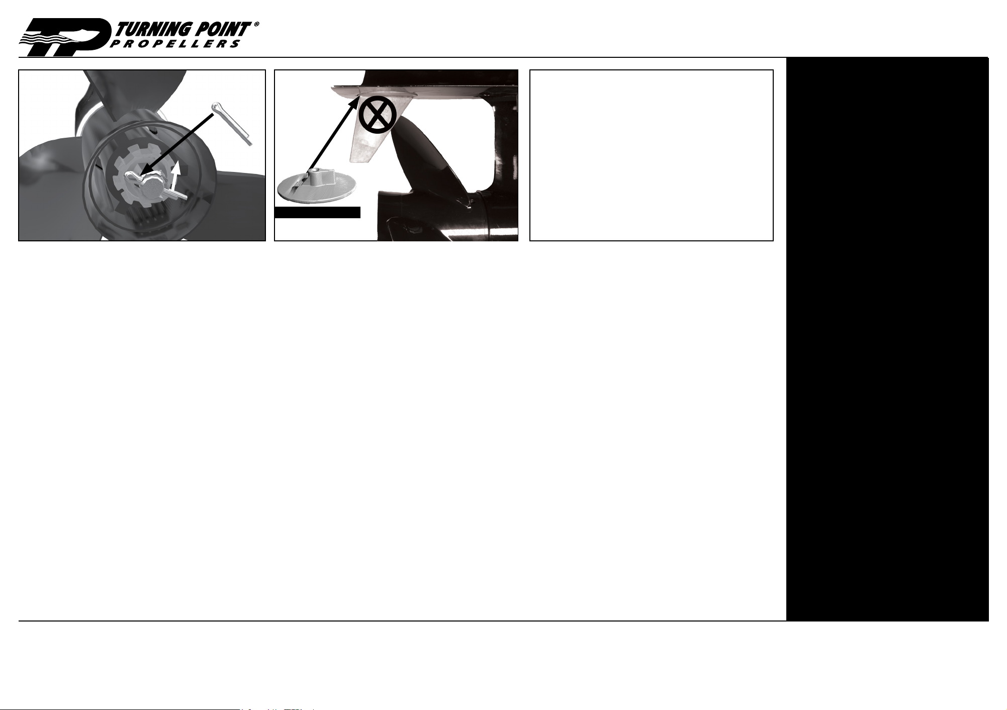
manuals.online logo
Brands
  1. Home
  2. •
  3. Brands
  4. •
  5. Turning Point Propellers
  6. •
  7. Boating Equipment
  8. •
  9. Turning Point Propellers 705 User manual

Turning Point Propellers 705 User manual

3
4
2
Part #41550900
Slide hub bushing into propeller housing from the front. Seating the
hub bushing completely to the bottom may require a few taps with a
mallet until recessed.
Deslize el cojinete en la cavidad de la hélice por el frente. Para
acomodar el cojinete completamente puede que sea necesario
golpearlo ligeramente con un mazo/martillo de goma.
Glisser la bague dans le logement par l’avant. La placer complètement
au fond peut nécessiter quelques coups avec un maillet en caoutchouc.
Elle doit être à eur ou légèrement encastrée dans son logement.
Model #
Part #
Fits
Mfg.
Gearcase
HP
Use Prop
w/ Icon KIT CONTENTS Thrust
Washer
Bushing Castellated
Prop Nut
Spacer
Washer Anode
705
11700500 Yamaha 4.75"
200-300hp
15 spline
41550900 41711040 41410500
(15mm)
41510510
(2mm) 41505060
PAGE 1 of 2
Caution: If a thrust washer is not used, severe damage could occur to
propeller and/or engine drive.
Attention: si on n’utilise pas de rondelle butée, des dégâts importants
pourraient être occasionnés à l’hélice et/ou au système de propulsion.
Aviso: Si no usa la arandela thrust, puede causar daños severos a
la hélice ó transmisión del motor.
1
Part #41711040
If you have any questions, please contact your Dealer
or our Product Support (Ext. 1).
Si vous avez des questions, contactez votre revendeur
ou notre ligne d’aide pour nos produits.
Si tiene preguntas ó dudas, pongase en contacto con
su Dealer local ó llamenos a nuestra línea de servicio
al cliente.
Turning Point Propellers, Inc.
11762 Marco Beach Dr Ste. 2
Jacksonville, FL 32224, USA
phone: +1(904) 900-7739 Ext. 1
email: [email protected]
web: http://tpprops.com
US Patent #5,967,751 #6,358,008, #6,471,481,
#7,717,678 & Worldwide Patented with Patents
Pending.
Version / Part#: 91270500
Replace your thrust washer with the one included in the kit. Slide with
the tapered end in rst to match the tapered surface of the prop shaft.
Remplacer la rondelle de butée du constructeur par celle qui est fournie
dans le kit. Glisser l’extrémité conique en premier pours’adapter à la
surface conique de l’arbre d’hélice.
Glisser la bague dans le logement par l’avant. La placer complètement
au fond peut nécessiter quelques coups avec un maillet en caoutchouc.
Elle doit être à eur ou légèrement encastrée dans son logement.
Clean and grease the spline of the prop shaft (Any marine grade
grease is acceptable). Slide the prop assembly (from step 1) on the
prop shaft.
Nettoyer et graisser les cannelures de l’arbre d’hélice (N’importe
quelle graisse marine de qualité peut être utilisée). Glisser le tout (à
partir de l’étape 1) sur l’arbre d’hélice.
Limpie y engrase el barril de la hélice (cualquier tipo de lubricante
marino es aceptable). Deslice el ensamble de la hélice (del paso No.
1) sobre el eje de la hélice.
Slide the washer onto the prop shaft.
Faites glisser la rondelle entretoise sur l’arbre d’hélice.
Deslice la arandela espaciadora en el eje de la hélice.
5 6
Installation Instructions KIT #705 (part# 11700500)
WARNING: This product is manufactured
of marine brass, which contains lead in
its metal matrix. This is an element known to the
State of California to cause cancer, birth defects,
or other reproductive harm if ingested. Please do
not eat this hub. Visit www.P65Warnings.ca.gov
CAUTION: FAILURE TO FOLLOW THESE
INSTRUCTIONS VOIDS THE WARRANTY.
Before servicing propeller, be sure the engine is
in neutral and disconnected from starting battery
positive lead to avoid any possibility of the engine
starting and causing injury or death. A spinning
propeller can be dangerous. Do not approach it
while the motor is operating and active. It can
cause serious injury or death.
ATTENTION: NE PAS SUIVRE CES
INSTRUCTIONS ANNULE LA GARANTIE.
Avant de procéder à la révision de l’hélice, vérier
que le moteur soit au point mort et déconnecté
de la borne positive de la batterie pour éviter
tout démarrage du moteur qui causerait de
graves blessures, potentiellement mortelles. Une
hélice qui tourne peut être dangereuse. Ne pas
s’en approcher pendant que le moteur tourne.
Cela peut provoquer de graves blessures,
potentiellement mortelles.
AVISO: FALLA A SEGUIR LAS
INSTRUCCIONES ANULA LA GARANTIA.
Antes de darle servicio a la hélice, asegurese que
el motor se encuentre en neutral y desconectado
del polo positivo de la batería para evitar la
posibilidad de que el motor arranque y pueda
causar heridas serias ó muerte. Una hélice en
movimiento puede ser peligrosa. No se aproxime
mientras el motor esté operando y activo. Puede
que cause accidentes serios y hasta la muerte.
Slide the castellated prop nut spacer onto the prop shaft. Prop nut
spacer does not need to engage prop shaft splines.
Glissez l’entretoise d’écrou dentelée sur l’arbre d’hélice. Il n’est pas nécessaire
d’engager la rondelle de friction dans les cannelures de l’arbre d’hélice.
Inserte la tuerca almenada en el eje de la hélice. No es necesario/
recomendado que la tuerca espaciadora entre en contacto con el barril
de la hélice (sección ranurada).
Serrez votre écrou d’hélice existant selon votre manuel d’utilisation du moteur
pour obtenir le couple approprié (55-80 pi-lb dans la plupart des cas). Alignez
les encoches de l’écrou avec l’orice de la goupille de l’arbre d’hélice.
Tighten your existing prop nut per your Engine Owner’s Manual for
proper torque (55-80 ft-lb in most cases). Align nut slots with prop
shaft cotter pin hole.
Apriete la tuerca de la hélice de acuerdo a las especicaciones del
Manual de Operador (generalmente entre 55-80 pies/lb). Alinear las
ranuras de la tuerca con el pin de chaveta de la hélice.
Part #41410500 (15mm) Part #41510510 (2mm)
IMPORTANT!
INSTALLATION NOTES
Periodically check prop surface for nicks or bent blade;
replace damaged prop immediately. Check prop nut
tightness to owner’s manual specication.
To remove hub bushing from prop housing, use 1” OD
rod or socket to tap out from prop nut end.
IMPORTANT!
NOTAS DE LA INSTALACIÓN
Contrôler régulièrement la surface de l’hélice pour
déceler les ssures ou les déformations des pales;
remplacer immédiatement l’hélice endommagée.
Contrôler le serrage de l’écrou de l’hélice selon les
spécications du manuel d’utilisation.
Pour enlever le moyeu de son logement, utiliser un
jet de Ø1” / 25,4mm ou une douille pour la sortir de
l’extrémité de l’écrou de l’hélice.
IMPORTANTE!
NOTES D’INSTALLATION
Chequee la supercie de la hélice periodicamente
para determinar si tiene arañazos o está torcida,
reemplaze la hélice inmediatamente si está dañada.
Asegurese que la tuerca esté ajustada de acuerdo a
las especicaciones del Manual del Propietario.
Para remover el cojinete del buje de la cavidad de la
hélice, use una varilla ó o socket de 1” de diámetro
externo para separarlo de la tuerca de la hélice.
Limited Warranty: Any claim under the warranty must be in writing.
Turning Point Propellers, Inc. warrants its propellers and hub kits against failure due to defects in materials and workmanship to the original purchaser.
CONSUMER USE: Housings - One Year from Date of Purchase; 705 HUB - Lifetime Limited Warranty on 200+hp applications. COMMERCIAL USE:
Housings - One Year from Date of Purchase; Hubs – One Year from Date of Purchase. This warranty is not transferable to any subsequent purchaser.
Turning Point Propellers, Inc. will repair or replace any defective propeller or hub under the terms of this warranty at our Jacksonville, FL facility or at our
option at an authorized repair center. Replacement or repair by other than Turning Point Propellers, Inc. or an authorized repair center relieves Turning
Point Propellers, Inc. from the terms of this warranty. This limited warranty does not include any of the following: damages caused by misuse, striking a
foreign object, corrosion, cavitation, electro-chemical action, improper installation, or any modication or use in racing or any other competitive activity.
Turning Point Propellers, Inc. is not liable for consequential, incidental or indirect damages or costs caused by defects in material or workmanship.
Observation of a defect requires that you stop use of the product, and immediately report the defect to Turning Point Propellers, Inc. or an authorized
repair center. Turning Point Propellers, Inc. reserves the right to repair or replace the warranted propeller and/or hub with one of current production.
This is a Limited Warranty. Turning Point Propellers, Inc. makes no warranty other than contained herein. All obligations of Turning Point Propellers, Inc.
are specically set forth herein. Turning Point Propellers, Inc. does not authorize any person or business to assume liability or contact on behalf of Turning
Point Propellers, Inc. Any actions arising out of this warranty and the sale of this product shall be governed by Florida law and may only be brought, heard,
decided in Duval County Circuit Court, in the State of Florida, U.S.A. or in the United States District Court for the Northern District of Florida.
Proof of purchase receipt must accompany any warranty claim
Reinstall cotter pin and bend ends.
Réinstaller la clavette et courber les extrémités.
reinstale el cotter pin y tuerza los terminales.
PAGE 2 of 2
7
Rotate propeller in neutral by hand to make sure it rotates freely. If
propeller strikes trim tab, replace with Turning Point Propellers at
anode #41505060.
Faire tourner l’hélice manuellement au point mort pour
s’assurer qu’elle tourne librement et qu’elle ne frotte pas contre
le carter de la boîte de vitesse. Si l’hélice touche l’anode, remplacez-
la par une anode plate Turning Point Propellers #41505060.
Rote la hélice manualmente (en neutral) para asegurar que
rote libremente y no roce con otras partes del motor. Si la hélice golpea
contra los aps, reemplaze con el ánodo plano modelo Turning Point
Propellers 41505060.
Part #41505060
8 9 IMPORTANT!
After installing the propeller, with the engine in the NEUTRAL
position, carefully spin the propeller by hand to make sure
it rotates freely. If propeller spins off-center, check for bent
prop shaft.
IMPORTANT!
Après l’installation de l’hélice avec le moteur AU POINT
MORT, tournez délicatement l’hélice à la main pour vous
assurer qu’elle tourne librement. Si l’hélice tourne de
façon décentrée, vériez si l’arbre d’hélice n’est pas plié.
IMPORTANTE!
Después de instalar la hélice, con el motor en Neutral,
gire la hélice manualmente para asegurarse que esté
bien encentrada. Si la hélice esta descentrada, revise si
el eje de la hélice para asegurarse que no esté torcido.
Installation Instructions KIT #705 (part# 11700500)

Other Turning Point Propellers Boating Equipment manuals

Turning Point Propellers 701 User manual

Turning Point Propellers

Turning Point Propellers 701 User manual

Turning Point Propellers MASTERGUARD 701 User manual

Turning Point Propellers

Turning Point Propellers MASTERGUARD 701 User manual

Popular Boating Equipment manuals by other brands

Simrad TP10 Service manual

Simrad

Simrad TP10 Service manual

Vetus FTANK25 Installation instructions and owner's manual

Vetus

Vetus FTANK25 Installation instructions and owner's manual

Yacht Devices YDEG-04 user manual

Yacht Devices

Yacht Devices YDEG-04 user manual

Thrane&Thrane SAILOR 500 FleetBroadband user manual

Thrane&Thrane

Thrane&Thrane SAILOR 500 FleetBroadband user manual

Vetus NLPH40 installation instructions

Vetus

Vetus NLPH40 installation instructions

Lofrans GALAXY 703 Installation and user manual

Lofrans

Lofrans GALAXY 703 Installation and user manual

Dock Doctors SLIDING BOARDING STEP Assembly instructions

Dock Doctors

Dock Doctors SLIDING BOARDING STEP Assembly instructions

NUCANOE 3005 Assembly instructions

NUCANOE

NUCANOE 3005 Assembly instructions

Mantagua 00086 user guide

Mantagua

Mantagua 00086 user guide

Malone MPG460G Assembly instructions

Malone

Malone MPG460G Assembly instructions

Floe INSTA-FLOAT Instructions & warnings

Floe

Floe INSTA-FLOAT Instructions & warnings

Native Watercraft ULTIMATE 14.5 owner's manual

Native Watercraft

Native Watercraft ULTIMATE 14.5 owner's manual

Plastimo PWH 500 Installation, operation & maintenance instructions

Plastimo

Plastimo PWH 500 Installation, operation & maintenance instructions

Magma Rock 'n Roll R10-702 Assembly instructions

Magma

Magma Rock 'n Roll R10-702 Assembly instructions

Garelick 74003 Assembly and installation instructions

Garelick

Garelick 74003 Assembly and installation instructions

monster tower MT1 Installation instructions and owner's manual

monster tower

monster tower MT1 Installation instructions and owner's manual

Seafloor HydroLite-TM PLUS user manual

Seafloor

Seafloor HydroLite-TM PLUS user manual

Trailer Valet 5X Operation manual

Trailer Valet

Trailer Valet 5X Operation manual

manuals.online logo
manuals.online logoBrands
  • About & Mission
  • Contact us
  • Privacy Policy
  • Terms and Conditions

Copyright 2025 Manuals.Online. All Rights Reserved.