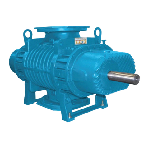
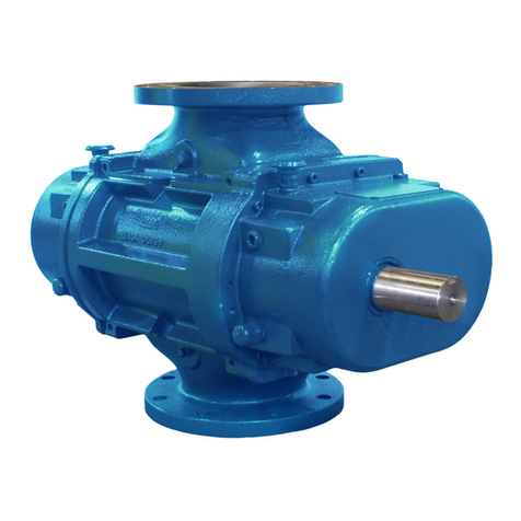
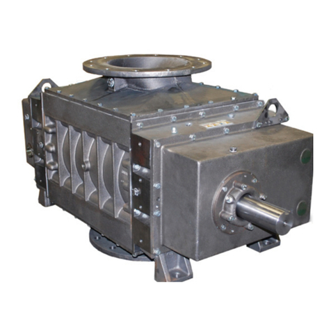
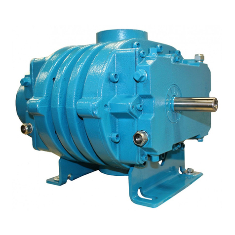
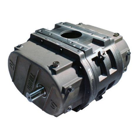
Tuthill T855RS User manual

Tuthill
Rotary Positive Displacement
Transport Blower
T855 / T855RS/T1055
OPERATOR’S MANUAL
Manual 2023 Rev G p/n 2023
WARNING: Do Not Operate Before Reading Manual
Operator’s Manual: Tuthill T855/T855RS/T1055 - Standard Weight Rotary Positive Displacement Transport Blower
Copyright © 2020 Tuthill Springeld
All rights reserved. Product information and specications subject to change.
Tuthill Springeld | tuthillvacuumblower.com | 800.825.6937
Models
T855 T1055
T855RS

Disclaimer Statement:
All information, illustrations and specications in this manual are based on the latest information available at
the time of publishing. The illustrations used in this manual are intended as representative reference views only.
Products are under a continous improvement policy. Thus, information, illustrations and/or specications to
explain and or exemplify a product, service or maintenance improvement may be changed at any time without
notice.
Rights Reserved Statement:
No part of this publication may be reproduced or used in any form by any means - graphic, electronic or me-
chanical, including photocopying, recording, taping or information storage and retrieval systems - without the
written permission of Tuthill Springeld.
Copyright © 2020 Tuthill Springeld
All rights reserved. Product information and specications subject to change.
The employees of Tuthill Springeld thank you for your purchase!
Tuthill Springeld proudly manufactures Kinney®vacuum
pumps and M-D PneumaticsTM blowers and vacuum boost-
ers in Springeld, Missouri, USA. We bring 100+ years of
engineering experience and solid, hands-on care to help
customers keep their processes running. Your satisfaction
is important to us so please take time to provide your Tuthill
sales representative with performance feedback. We love to
hear from our customers!
Tuthill is a family owned business that was started by James
B. Tuthill in 1892. At that time, Tuthill manufactured com-
mon brick to Chicago construction companies who were
fueling the city’s rapid expansion. Fast forward to today
and Tuthill now serves sustaining, global markets like agri-
culture, chemical, construction, energy, food and beverage,
pharmaceuticals and medical, transportation, and utilities.
While the company has changed in what it manufactures,
one thing remains throughout every Tuthill line of business
– we are a company with HEART. Our slogan is “Pump Your
Heart Into It” and everyday our employees do just that as
they represent the Tuthill brand and dare to make better.
Thank you for making Tuthill Springeld part of your com-
pany’s process! FIND OUT MORE AT
TUTHILL.COM
A company with heart
right from the start.

Operator’s Manual 2023 Rev G p/n 2023 i
Table of Contents
Table of Contents
Introduction .................................................................................. 1
Safety ............................................................................................ 2
Graphic Conventions in this Manual ..................................................... 2
Safety Instructions................................................................................. 3
Safety Precautions ..................................................................... 3
T855RS.......................................................................................... 4
RS Advanced Technology Features & Benefits..................................... 4
Mounting ............................................................................................... 4
Specifications........................................................................................ 5
Installation .................................................................................... 6
Safety Checklist .................................................................................... 6
Specifications........................................................................................ 7
Outline Drawings................................................................................... 8
T855 / T855RS / T1055 Vent Holes ....................................................... 9
PTO Selection for Transmission........................................................... 10
Engine Speed ..................................................................................... 10
Pressure Relief Valve .......................................................................... 10
Air Filter ............................................................................................... 10
Suction and Discharge Piping ............................................................ 10

Operator’s Manual 2023 Rev G p/n 2023
ii
Table of Contents
Mounting Bracket ................................................................................ 10
T855 & T855RS Optional Mounting Adaptor Plate.............................. 11
Mounting Adaptor Plate Kit: 61590 .......................................... 11
Torque Values........................................................................... 11
Check Valve ........................................................................................ 12
Mufflers and Discharge Filtration ........................................................ 12
Vacuum Valve...................................................................................... 12
Performance Curves ........................................................................... 14
Performance Curves (US) ........................................................ 14
Performance Curves (Metric) ................................................... 18
Lubrication .......................................................................................... 22
Filling Procedure ...................................................................... 22
Operation .................................................................................... 24
Maintenance ............................................................................... 25
Regular Maintenance.......................................................................... 25
Blower Service & Repair ..................................................................... 25
Recommended Lubricants........................................................ 26
Recommended Lubricants for Rotary Blowers and Vacuum
Boosters.............................................................................................. 26
Assembly Drawing and Parts List ............................................ 28
Assembly Drawing .............................................................................. 28
Parts List ............................................................................................. 29
Warranty – Blower Products...................................................... 30
Operating Data Form / Product Registration............................ 31

Operator’s Manual 2023 Rev F p/n 2023 1
CONGRATULATIONS on the purchase of a new
Tuthill Transport Blower. Please examine the
blower for shipping damage, and if any damage
is found, report it immediately to the carrier. If
the blower is to be installed at a later date, make
sure it is stored in a clean, dry location and
rotated monthly. Make sure covers are kept on all
openings. If the blower is stored outdoors, be sure
to protect it from weather and corrosion.
Tuthill Transport Blowers are built to exacting
standards and, if properly installed and maintained,
will provide many years of reliable service. Read
and follow every step of these instructions when
installing and maintaining the blower.
OTE:N Record the blower model and serial
numbers of the machine in the
OPERATING DATA form on the inside
back cover of this manual. Use this
identication on any replacement part
orders, or if service or application
assistance is required.
INTRODUCTION
01

Operator’s Manual 2023 Rev G p/n 2023
2
GRAPHIC CONVENTIONS IN THIS
MANUAL
The following hazard levels are referenced within
this manual:
DANGER
!
Indicates a hazardous situation that, if not
avoided, will result in death or serious injury.
WARNING
!
Indicates a hazardous situation that, if not
avoided, could result in death or serious
injury.
CAUTION
!
Indicates a hazardous situation that, if not
avoided, could result in minor or moderate
injury.
Indicates a situation that can cause damage
to equipment, personal property, and/or
the environment or cause the equipment to
operate improperly.
OTE:N Indicates a procedure, practice, or
condition that should be followed in
order for the equipment to function in the
manner intended.
CAUTION
!
Read manual before operation
or bodily harm may result.
Attention should be given to the
safety related sections of this
manual.
SAFETY INSTRUCTIONS
1. Do not operate before reading the enclosed
instruction manual.
2. Use adequate protection, warning and safety
equipment necessary to protect against
hazards involved in installation and operation
of this equipment.
SAFETY
02

Operator’s Manual 2023 Rev G p/n 2023 3
02
Safety
WARNING
Hearing
Protection
Required
WARNING
Keep body and
clothing away from
machine openings.
CAUTION
Do not
touch hot
surfaces.
WARNING
Keep body
and clothing away
from drive shaft.
The above safety instruction tags were
attached to your unit prior to shipment. Do not
remove, paint over or obscure in any manner.
Failure to heed these warnings could result in
serious bodily injury to the personnel operating
and maintaining this equipment.
WARNING
!
• Keep hands and clothing away from
rotating machinery, inlet and discharge
openings.
• Blower and drive mounting bolts must be
secured.
• Drive belts and coupling guards must be
in place.
• Noise level may require ear protection.
• Blower heat can cause burns if touched.
Safety Precautions
For equipment covered specically or indirectly
in this operator’s manual, it is important that all
personnel observe safety precautions to minimize
the chances of injury. Among many considerations,
the following should particularly be noted:
• Rotating shafts can be dangerous. You can
snag clothes, skin, hair, hands, etc. This can
cause serious injury or death.
• Do not work under the vehicle while the engine
is running.
• Do not work on a shaft (with or without a guard)
while the engine is running.
• Do not engage or disengage driven equipment
by hand from under the vehicle while the engine
is running.
• In order to avoid becoming entangled, install the
power take off and/or shaft behind the frame rail,
tanks, battery box, etc.
• If power take off and/or shaft are still exposed
after installation, install a guard.
• Install a support strap when servicing a drive
shaft to prevent personal injury.
A SERIOUS OR FATAL INJURY CAN OCCUR:
• If you lack proper training
• If you fail to follow proper procedures
• If you do not use proper tools and safety
equipment
• If you assemble drive line components
improperly
• If you use incompatible drive line components
• If you use worn out or damaged drive line
components
• If you use drive line components in a
non‑approved application
This manual contains safety instructions. Read,
understand and follow this manual.
• Get proper training
• Learn and follow safe operating procedures
• Use proper tools and safety equipment
• Use proper components in good condition
Operator’s Manual 2023 Rev G p/n 2023
4
T855RS
03
RS ADVANCED TECHNOLOGY
FEATURES & BENEFITS
This section is for items specic to blowers
enhanced with Tuthill RS Advanced Technology.
Please see remainder of this manual for all
other blower specications as well as safety
warnings and precautions.
Tuthill’s T855RS Advanced Technology transport
blowers are designed for the loading and
unloading of cement, y ash, powders, crushed
limestone, sand, and granular materials. They offer
customers:
• Widest range of ow of any blower on the
transport market
• Reduces ofoad times by as much as 25%
• Can run quieter than many other blowers thanks
to lower operating speeds
• Less net fuel consumption
• Vacuum performance to 18" Hg
• Operates slower yet moves more product
• Operates cooler, less oil changes when Tuthill
premium lubricants are used
• Overall longer life
• Abradable / formable coating on rotor lobes
reduces and tightens clearances; reduces slip
See Figure 3-1
OIL CAPACITIES (SAME AS T855)
Horizontal Air
Flow (Standard)
Vertical Air Flow
(Standard)
Drive
End
1.06 quarts 1.68 quarts
34 oz. 54 oz.
1005.5 mL 1597 mL
Non‑Drive
(Gear)
End
1 quart 1.75 quarts
32 oz. 56 oz.
946.3 mL 1656 mL
Every Transport Blower is shipped with 1 gallon of
Tuthill MD full synthetic oil to ensure the very best
lubrication of bearings, gears, and seals.
MOUNTING
The T855RS can be mounted in vertical or
horizontal ow conguration. Tuthill now offers an
optional mounting plate adaptor that can be used
to mount the T855RS on many L‑Style vertical ow
brackets.See T855 & T855RS Optional Mounting
Adaptor Plate on page 11.
Figure 3-1 – T855RS Rotor with
RS Advanced Technology Coating

Operator’s Manual 2023 Rev G p/n 2023 5
03
T855RS
T855 with RS Advanced Technology™ Pressure Operating Parameters
RPM 7 PSIG 12 PSIG 16 PSIG 18 PSIG 20 PSIG
CFM BHP CFM BHP CFM BHP CFM BHP CFM BHP
600 127 6.5
750 194 5.8 147 13.7
1000 281 7.8 236 18.3 212 24.4 201 27.4
1250 333 8.9 323 22.9 301 30.5 289 34.2 278 38.0
1500 384 10.1 410 27.5 388 36.5 377 41.1 367 45.6
1750 488 12.4 497 32.1 475 42.6 465 47.9 454 53.2
2000 627 15.5 584 36.6 562 48.7 552 54.8 542 60.8
2500 800 19.4 757 45.8 736 60.9 726 68.4 716 76.0
3000 973 23.3 930 55.0 909 73.1 899 82.1 889 91.2
Table 3-1 – T855RS Pressure Operating Parameters
T855 with RS Advanced Technology™ Vacuum Operating Parameters
RPM 2" Hg 10" Hg 12" Hg 17" Hg 18" Hg
CFM BHP CFM BHP CFM BHP CFM BHP CFM BHP
600 179 1.0 132.4 4.6 121 5.5
750 231 1.3 184.3 5.7 173 6.8 138 9.6
1000 318 1.7 270.8 7.6 259 9.1 224 12.8
1250 404 2.1 357.3 9.5 346 11.4 311 16.0
1500 491 2.5 443.8 11.4 432 13.6 397 19.2 389 20.3
1750 577 2.9 530.3 13.3 519 15.9 484 22.4 475 23.7
2000 664 3.4 616.8 15.2 605 18.2 570 25.6 562 27.1
2500 837 4.2 789.8 19.0 778 22.7 743 32.0 735 33.9
3000 1010 5.1 962.8 22.8 951 27.3 916 38.4 908 40.6
Table 3-2 – T855RS Vacuum Operating Parameters
SPECIFICATIONS
Blue cell coloring indicates new T855RS performance
capability parameters vs T855 standard.
Figure 3-2 – T855RS with Optional Mounting Plate Adaptor
Use caution when working around rotors as
damage to the coating could result in loss
of performance. Ensure inlet only receives
lteredcleanair.

Operator’s Manual 2023 Rev G p/n 2023
6
INSTALLATION
04
SAFETY CHECKLIST
Complete this checklist before operating the
blower.
TRUCK NUMBER BLOWER MODEL NUMBER
GEARBOX NUMBER BLOWER SERIAL NUMBER
P.T.O. NUMBER DATE INSTALLED
P.T.O. RATIO INSPECTED BY
Is ratio and horsepower correct for PTO?
Mount PTO as per manufacturer’s
recommendations and rell transmission.
Ensure oil levels are at the center of the sight
glass when blower is not running.
Without drive line connected, can the blower be
rotated by hand?
Is the drive line installed at the correct angle and
phase with all fasteners secured?
Ensure PTO rotates blower in the correct
direction indicated by arrow.
Ensure air inlet lter is connected and located
away from truck exhaust.
Remove Camlock dust cap, and discharge
piping open to atmosphere.
With tractor engine at idle, slowly engage PTO.
Check for correct rotation.
Slowly bring blower up to operating speed.
Check for vibration, mechanical noise, oil leaks
and mounting integrity.
Stop blower, connect blower discharge hose to
trailer, and run blower at operating pressure of
trailer for 15 minutes at normal speed.
Does relief valve allow 15 psig (1 bar g)
pressure for safety of trailer?
Does engine maintain correct RPM throughout
test?
Shut down machine. Check Shur‑Melt® plugs,
relief valve, lter, piping, and oil sumps for
integrity.
Is correct engine speed label visible in cab?

Operator’s Manual 2023 Rev G p/n 2023 7
04
Installation
WARNING
!
The blower and accessories will
become hot enough to cause serious
skin burns on contact.
Rotating machinery is dangerous.
Always wear ear protection when
near an operating blower.
SPECIFICATIONS
MODEL AIR FLOW RANGE MAXIMUM
PRESSURE
MAXIMUM
VACUUM RPM RANGE
T855 250 – 1,000 CFM
(424 – 1,699 m³/h)
20 psig
(1.37 bar g)
17 inch‑Hg
(575 Mbar)
1,000 – 3,000
(Pressure)
750 – 3,000
(Vacuum)
T1055 450 – 1,300 CFM
(765 – 2,209 m³/h)
18 psig
(1.24 bar g)
17 inch‑Hg
(575 Mbar)
1,200 – 3,000
(Pressure & Vacuum)
T855RS 121– 1,010 CFM
(206 – 1,716 m³/h)
20 psig
(1.37 bar g)
18 inch‑Hg
(609 Mbar)
600 – 3,000
(Pressure & Vacuum)
OTE:NReduce the maximum operating pressure by 1 psi (0.068 bar) for each 2,000 feet (610 m) of
elevation above sea level.
Example: At an elevation of 4,000 feet (1,219 m), the maximum working pressure of the blower will
decrease by 2 psi (0.137 bar).
Table 4-1 – Specifications

Operator’s Manual 2023 Rev G p/n 2023
8
04
Installation
OUTLINE DRAWINGS
Dimensions shown are not on a controlled
document and as such are subject to change.
Certied drawings are available through your
local Tuthill Transport Blower Channel Partner.
Dimensions are shown in inches and millimeters.
Figure 4-1 – Outline Drawings
OTE:NT855RS dimension specication
match˛model T855.

Operator’s Manual 2023 Rev G p/n 2023 9
04
Installation
T855 / T855RS / T1055
VENT HOLES
Each transport blower is supplied with 4 vent plugs
that should be installed in the top four vent holes
once the nal mounting orientation of the blower is
determined.
Another option (not included), depending on
mounting bracket space, is to use 90° elbows with
or without exible tubing. If you choose to use vent
plugs, then follow the subsequent instructions. The
exact plug location will vary based on the mounting
position.
The image below shows one option for the vent
hole locations on a horizontal airow mount.
Figure 4-2 – Mounting Configuration
In this mounting conguration (See Figure 4-2)
the four holes (two are shown and two are on the
opposite side top) could have plugs added to them.
This would leave the four holes on the bottom of
the unit open or 90° 1/8" NPT elbows that face
down.
Four vent holes should always be open to air. You
can plug all the holes on the bracket side, then use
four 90° elbows on the non‑bracket side (horizontal
mount). Or you can plug two on each end plate at
the top side and leave two on each end plate at the
bottom open.
CAUTION
!
Never plug all the vent holes or serious damage to
seals and bearings will result. Four vent holes (two
per side or all four on one side) must always be open.
Figure 4-3 – Alternate plug configuration: Horizontal
mount with holes plugged on the bracket side
Figure 4-4 – Alternate plug configuration: Horizontal
mount with street elbows

Operator’s Manual 2023 Rev G p/n 2023
10
04
Installation
PTO SELECTION FOR
TRANSMISSION
Blower speed and pressure require adequate
horsepower and torque. See Performance Curves
on page 14.
Engine speed and blower speed require the
adequate ratio PTO be installed for proper blower
operation.
ENGINE SPEED
Keep engine speed constant when the blower is
in the operating cycle. Install a constant‑speed
governor or throttle control system to ensure
proper blower operation.
PRESSURE RELIEF VALVE
Size the pressure relief valve for the correct air ow
and pressure rating. Install the valve as close to
the blower as possible and before the check valve.
Ensure that pipe compound is used on the threads
of the male end of the relief valve to seal against
air leakage.
An undersized or improperly set relief valve
will cause the blower to operate at higher
temperatures. This can cause the blower to
overheat, causing irreparable damage.
AIR FILTER
Select a lter suitable for the air ow requirement
of the application. Use air lters on food and plastic
products to prevent contamination.
Anundersizedairlterwillcausetheblower
to operate at higher temperatures. This can
cause blower to overheat, causing irreparable
damage.
SUCTION AND DISCHARGE PIPING
All piping should be free and clear of any welding
slag or foreign material.
The suction piping requirement is a minimum
of 5 in. (127 mm) diameter for proper ow to
the blower.
Discharge piping is a minimum of 4 in.
(102 mm) diameter.
Do not use a rubber elbow in the suction line
during vacuum operation. The elbow will fail
causing the blower to overheat. This will cause
damage to the blower.
MOUNTING BRACKET
To reduce stress on the blower housing, be sure to
properly mount the blower with the correct bracket.

Operator’s Manual 2023 Rev G p/n 2023 11
04
Installation
T855 & T855RS OPTIONAL
MOUNTING ADAPTOR PLATE
The Adaptor Plate allows easy conversion from
other manufacturer’s blowers that utilize L‑style
brackets and 3" NPT plumbing.
Figure 4-5 – Optional Mounting Adaptor Plate Kit
Exploded Part Diagram with T855RS
Mounting Adaptor Plate Kit: 61590
Steps for installation:
1. Place the gasket over the 4 aligning bolt holes
at the discharge (top) port.
2. Attach Adaptor Plate to the T855RS blower by
placing it on top of the blower and gasket.
3. Secure the Adaptor Plate to the blower using
the four 5/8"‑11 x 1‑1/4" Flat Socket Head Cap
Screws and four 1/2" ‑13 x 1‑1/4" Flat Socket
Head Cap Screws.
4. Attach the blower / adaptor assembly to the
L‑Bracket using four 5/8"‑18 x 1‑1/4" Hex Head
Screws with the Split Lock Washer between
the screw head and top of the L‑Bracket.
Use removable threadlocker during installation
of the 5/8"-18 bolt in combination with the split
lock washer.
OTE:NIncludes plate, mounting bolts,
and gasket.
Contact Tuthill or your authorized Tuthill
representation for more details or inquiries.
Torque Values
Bolt Size Torque
(in.-lbs.)
1/2"‑13 80
5/8"‑11 150
5/8"‑18 170
Always ensure the diagonal straps are used on
the L-bracket (not provided by Tuthill).
Donotovertightenthedischargettingintothe
plate. Overtightening can damage the plate
and the blower.
Use only bolts / hardware included with the
adaptor plate. Using old bolts may damage
plate due to differences in thread.

Operator’s Manual 2023 Rev G p/n 2023
12
04
Installation
CHECK VALVE
Minimum restriction for application. Mount
downstream of the relief valve. Size the valve for
maximum air ow (CFM or m³/hr).
MUFFLERS AND DISCHARGE
FILTRATION
Minimum restriction for application. Mount
downstream of the relief valve.
VACUUM VALVE
Size for proper air ow and vacuum rating.
This valve should be located before the blower
inlet lter. This valve is normally mounted on the
trailer.
To properly protect the blower from
overheating when vacuum loading, install a
vacuum valve.

Operator’s Manual 2023 Rev G p/n 2023 13
04
Installation
RIGHT DRIVE CCW ROTATION LEFT DRIVE CW ROTATION
Figure 4-15 – Flow Direction and Rotation

Operator’s Manual 2023 Rev G p/n 2023
14
04
Installation
PERFORMANCE CURVES
PERFORMANCE CURVES (US)
T850 / T855 PRESSURE CURVE
2
5
8
12
15
18
20
PSIG
PSIG
20
18
15
12
8
5
2
1000 15002000
RPM
Airflow at Inlet (CFM)
2500 3000 0
25
200
300
400
500
600
700
800
900
1000
50
75
100
BHP
AIRFLOW BASED UPON INLET
CONDITIONS OF: 14.7 PSIA & 70° F
# PSIG DISCHARGE PRESSURE
Figure 4-6 – T850 / T855 Pressure Curve (US)

Operator’s Manual 2023 Rev G p/n 2023 15
04
Installation
T850 / T855 VACUUM CURVE
2
6
10
14
17
In. Hg
In. Hg
17
14
10
6
2
1000 1500 2000
RPM
2500 3000
Airflow at Inlet (CFM)
200
300
400
500
600
700
800
900
1000
0
25
50
75
100
BHP
AIRFLOW BASED UPON
INLET: 70° F
DISCHARGE: 29.92" Hg Abs
Figure 4-7 – T850 / T855 Vacuum Curve (US)

Operator’s Manual 2023 Rev G p/n 2023
16
04
Installation
T1050 / T1055 PRESSURE CURVE
2
5
8
10
12
15
18
PSIG
PSIG
18
15
12
10
8
5
2
10001500 2000
RPM
2500 3000
Airflow at Inlet (CFM)
0
150
300
450
600
750
900
1050
1200
1350
0
15
30
45
60
75
90
105
120
BH
P
AIRFLOW BASED UPON INLET
CONDITIONS OF: 14.7 PSIA & 70° F
# PSIG DISCHARGE PRESSURE
Figure 4-8 – T1050 / T1055 Pressure Curve (US)
This manual suits for next models
2
Table of contents
Other Tuthill Blower manuals

Tuthill
Tuthill M-D Pneumatics PD PLUS 17/46 Series Operating instructions

Tuthill
Tuthill PD Plus 1215 User manual

Tuthill
Tuthill M-D Pneumatics Qube 400 User manual

Tuthill
Tuthill PD Plus User manual

Tuthill
Tuthill Qx Series User manual

Tuthill
Tuthill Qx 3200 Series Operating instructions

Tuthill
Tuthill TI850 Operating instructions

Tuthill
Tuthill T855 User manual

Tuthill
Tuthill M-D Pneumatics PD PLUS 64/67 Series Operating instructions

Tuthill
Tuthill PD Plus 9000 Series User manual