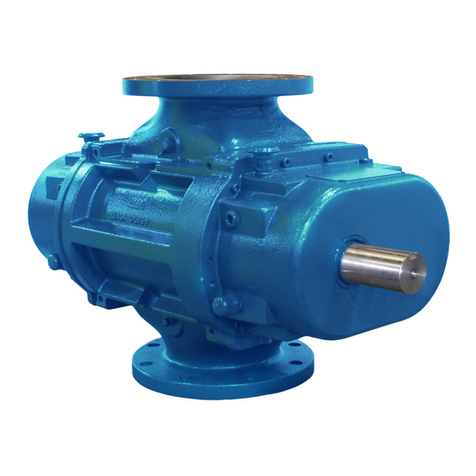
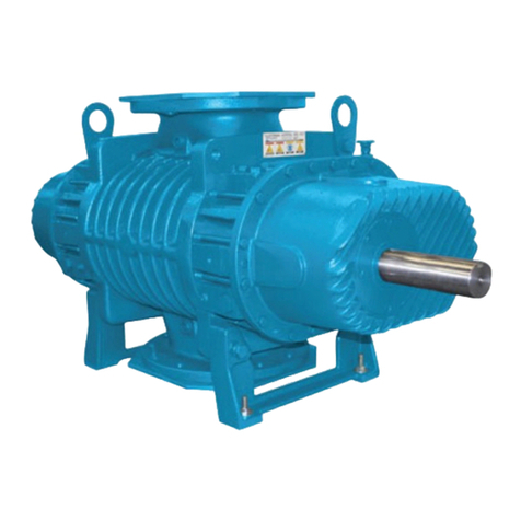
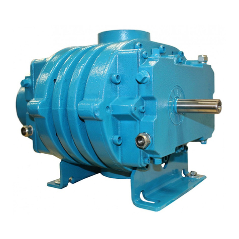
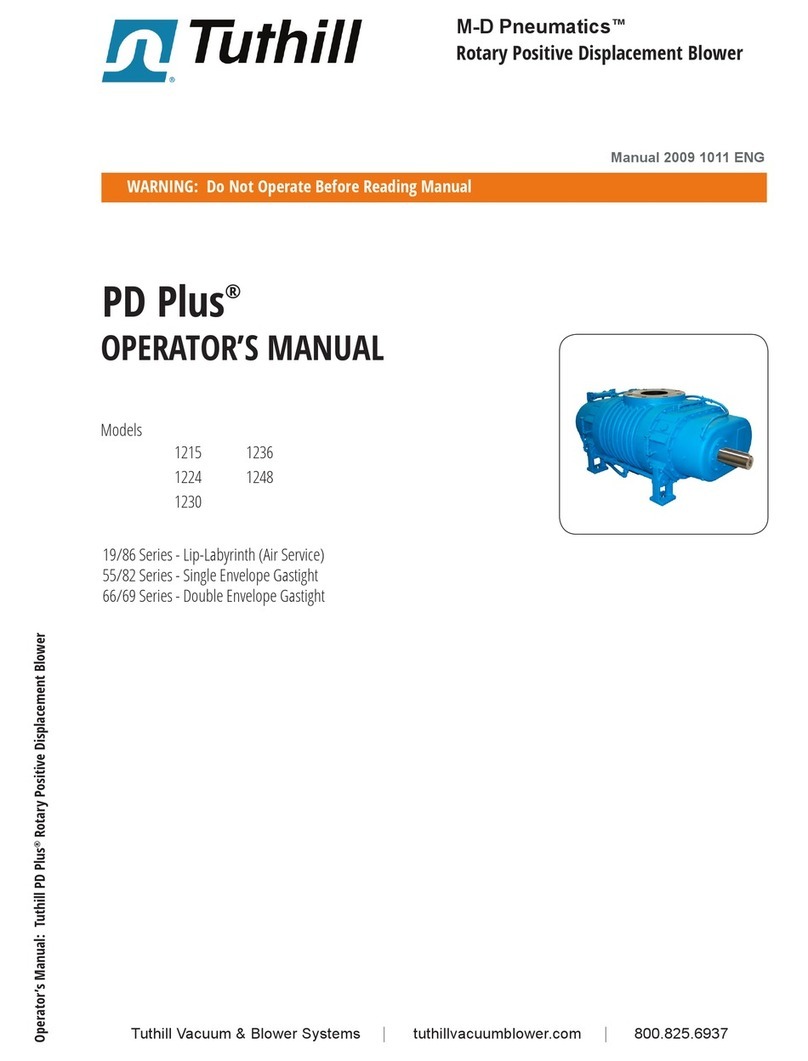
Tuthill PD Plus 1215 User manual

M-D Pneumatics™
Rotary Positive Displacement Blower
PD Plus®
Models
1215 1236
1224 1248
1230
Seal/Lube Series 5 or 19/86 Series - Lip-Labyrinth (Air Service)
Seal/Lube Series 8 or 55/82 Series - Single Envelope Gastight
Seal/Lube Series 9 or 66/69 Series - Double Envelope Gastight
OPERATOR’S MANUAL
Tuthill Vacuum & Blower Systems tuthillvacuumblower.com 800.825.6937
WARNING: Do Not Operate Before Reading Manual
Operator’s Manual: Tuthill PD Plus Rotary Positive Displacement Blower
Copyright © 2018 Tuthill Vacuum & Blower Systems
All rights reserved. Product information and specications subject to change.
Manual 2009 Rev B p/n 2009

Disclaimer Statement:
All information, illustrations and specications in this manual are based on the latest information available at
the time of publishing. The illustrations used in this manual are intended as representative reference views only.
Products are under a continuous improvement policy. Thus, information, illustrations and/or specications to
explain and or exemplify a product, service or maintenance improvement may be changed at any time without
notice.
Rights Reserved Statement:
No part of this publication may be reproduced or used in any form by any means - graphic, electronic or me-
chanical, including photocopying, recording, taping or information storage and retrieval systems - without the
written permission of Tuthill Vacuum & Blower Systems.
Copyright © 2018 Tuthill Vacuum & Blower Systems
All rights reserved. Product information and specications subject to change.
The employees of Tuthill Vacuum & Blower Systems thank you for your purchase!
Tuthill Vacuum & Blower Systems proudly manufactures
Kinney®vacuum pumps and M-D PneumaticsTM blowers and
vacuum boosters in Springeld, Missouri, USA. We bring
100+ years of engineering experience and solid, hands-
on care to help customers keep their processes running.
Your satisfaction is important to us so please take time to
provide your Tuthill sales representative with performance
feedback. We love to hear from our customers!
Tuthill is a family owned business that was started by James
B. Tuthill in 1892. At that time, Tuthill manufactured com-
mon brick to Chicago construction companies who were
fueling the city’s rapid expansion. Fast forward to today
and Tuthill now serves sustaining, global markets like agri-
culture, chemical, construction, energy, food and beverage,
pharmaceuticals and medical, transportation, and utilities.
While the company has changed in what it manufactures,
one thing remains throughout every Tuthill line of business
– we are a company with HEART. Our slogan is “Pump Your
Heart Into It” and everyday our employees do just that as
they represent the Tuthill brand and dare to make better.
Thank you for making Tuthill Vacuum & Blower Systems
part of your company’s process! FIND OUT MORE AT
TUTHILL.COM
A company with heart
right from the start.
i
Operator’s Manual 2009 Rev B p/n 2009
Table of Contents
Introduction .................................................................................. 1
Applicable Documentation ................................................................... 1
Scope of Manual................................................................................... 1
Conventions and Data Plate ....................................................... 2
Graphic Conventions in this Manual ..................................................... 2
Data Plate.............................................................................................. 3
Lifting ............................................................................................ 5
Description ................................................................................... 6
Flow by Direction................................................................................... 7
Specifications........................................................................................ 8
Installation .................................................................................. 10
General ............................................................................................... 10
Location.................................................................................... 12
Foundation................................................................................ 12
Blower Air Intake ...................................................................... 12
Soft Foot ................................................................................... 13
Safety .................................................................................................. 13
Lubrication .......................................................................................... 14
Filling Procedure ...................................................................... 14

ii
Table of Contents
Operator’s Manual 2009 Rev B p/n 2009
Frequently Asked Questions Regarding Lubrication ............... 16
Recommended Oil Change Intervals....................................... 17
Hazards Associated With Breakdown or Ignition of
Lubrication ............................................................................... 17
Lubrication – Integral Pressure ........................................................... 17
Oil Filter .................................................................................... 17
Oil Pressure Adjustment........................................................... 18
Oil Cooler ................................................................................. 18
Piping Connections............................................................................. 18
Hazards Associated With Hazardous Process Fluids.............. 19
Blockage or Restriction ............................................................ 19
Motor Drives........................................................................................ 20
Direct Coupled ......................................................................... 20
V-Belts ...................................................................................... 20
Setting V-Belt Tension............................................................... 20
V-Belt Troubleshooting ............................................................. 22
Motor and Electrical Connections ............................................ 23
Operation .................................................................................... 24
General ............................................................................................... 24
Start-Up Checklist............................................................................... 25
Operating ............................................................................................ 26
Stopping.............................................................................................. 26
Water-Injected Blowers ....................................................................... 27
Operation ................................................................................. 27
Shutdown ................................................................................. 27
Recommended Shutdown Procedure to Minimize Risk of
Freezing or Corrosion ......................................................................... 27

iii
Table of Contents
Operator’s Manual 2009 Rev B p/n 2009
Maintenance ............................................................................... 29
General ............................................................................................... 29
Regular Maintenance.......................................................................... 29
Spare Parts ......................................................................................... 30
Factory Service and Repair ................................................................ 30
Long-Term Storage ............................................................................. 31
Disassembly and Reassembly.................................................. 32
Disassembly of Blower ....................................................................... 32
Free End Disassembly ............................................................. 32
Gear End Disassembly ........................................................... 32
End Plate and Rotor Disassembly............................................ 33
Assembly ............................................................................................ 33
Preparation of End Plates ........................................................ 34
Gear End Assembly ................................................................. 34
Free End Assembly .................................................................. 35
Adjusting Interlobe Clearance ................................................. 36
Completing Gear End Assembly.............................................. 37
Completing Free End Assembly .............................................. 37
Troubleshooting......................................................................... 38
Assembly Clearances................................................................ 40
Torque Chart............................................................................... 41
Recommended Lubricants........................................................ 42
Recommended Lubricants for Rotary Blowers and Vacuum
Boosters.............................................................................................. 42
Special Tool Drawings............................................................... 44
Parts List ............................................................................................. 46
Assembly Drawings ............................................................................ 49

iv
Table of Contents
Operator’s Manual 2009 Rev B p/n 2009
Declaration of Incorporation..................................................... 51
Warranty – Blower Products..................................................... 52
Operating Data Form / Product Registration........................... 53

1
Operator’s Manual 2009 Rev B p/n 2009
CONGRATULATIONS on the purchase of a new
PD PLUS®Rotary Positive Displacement Blower
from Tuthill Vacuum & Blower Systems. Please
examine the blower for shipping damage, and if
any damage is found, report it immediately to the
carrier. If the blower is to be installed at a later
date, make sure it is stored in a clean, dry location
and rotated regularly. Make sure covers are kept
on all openings. If blower is stored outdoors, be
sure to protect it from weather and corrosion.
PD PLUS blowers are built to exacting standards
and, if properly installed and maintained, will
provide many years of reliable service. Read
and follow every step of these instructions when
installing and maintaining your blower.
OTE:N Record the blower model and serial
numbers of the machine in the
OPERATING DATA form on the inside
back cover of this manual. Use this
identication on any replacement part
orders, or if service or application
assistance is required.
APPLICABLE DOCUMENTATION
The applicable documents associated with this
manual are:
• 2006/42/CE – Machinery Directive
• EN 1012-1:1996 - Compressors and vacuum
pumps - Safety Requirements - Part 1:
Compressors
SCOPE OF MANUAL
The scope of this manual and the Declaration of
Incorporation includes the bare shaft rotary positive
displacement blower.
INTRODUCTION
01

2Operator’s Manual 2009 Rev B p/n 2009
GRAPHIC CONVENTIONS IN THIS
MANUAL
This manual is the result of a risk assessment
according to the applicable documents referenced
in Applicable Documentation on page 1. The
following hazard levels are referenced within this
manual:
DANGER
!
Indicates a hazardous situation that, if not
avoided, will result in death or serious injury.
WARNING
!
Indicates a hazardous situation that, if not
avoided, could result in death or serious
injury.
CAUTION
!
Indicates a hazardous situation that, if not
avoided, could result in minor or moderate
injury.
Indicates a situation that can cause damage
to the engine, personal property, and/or
the environment or cause the equipment to
operate improperly.
OTE:N Indicates a procedure, practice, or
condition that should be followed in
order for the equipment to function in the
manner intended.
CAUTION
!
Read manual before operation
or bodily harm may result.
Attention should be given to the
safety related sections of this
manual.
CONVENTIONS AND DATA PLATE
02

3
02
Conventions and Data Plate
Operator’s Manual 2009 Rev B p/n 2009
DATA PLATE
WARNINGWARNING CAUTION CAUTION
http://www.tuthill.com
Hearing protection
re
q
uired.
Do not touch hot
surfaces.
ASUehtniedaM7396-528)008(
READ INSTRUCTION MANUAL BEFORE OPERATION OR BODILY HARM MAY RESULT
Keep body & clothing away
from machine openings.
Do not operate without
g
uards in
p
lace.
REBMUNLAIRESREBMUNLEDOM
Tuthill Vacuum & Blower Systems
4840 West Kearney Street
Springfield, Missouri USA 65803
YEARMAWP
MAX RPM
Figure 2-1 – General Operation and Symbols on Data Plate
The following information is contained on the data
plate:
WARNING
!
Keep body and clothing away
from machine.
During operation, keep body
and clothing away from inlet
and outlet of the blower.
WARNING
!
Do not operate without guards
in place.
CAUTION
!
Hearing protection is required
while the blower is in operation.
Noise levels may reach as high
as 81 dBA.
CAUTION
!
Do not touch hot surfaces.
The upper limit of the blower
operation is 400°F (205°C). Do
not touch the blower while it is
in operation and assure blower
is cool when not in operation.

4
02
Conventions and Data Plate
Operator’s Manual 2009 Rev B p/n 2009
MODEL NUMBER: The specic model of the blower
SERIAL NUMBER: Unique to each blower
YEAR: Year of manufacture
MAWP: Maximum Allowable Working Pressure
The standard MAWP is per Table 4-2 – Maximum Operating Limits on page
8. The MAWP shall not be exceeded.

5
Operator’s Manual 2009 Rev B p/n 2009
WARNING
!
The blower must be handled using an
appropriate device such as a fork truck or
appropriate lifting device. See Table 4-1 on
page 8 for approximate weights. Care
should be taken to assure blower does not
over-turn during handling and installation.
LIFTING
03

6Operator’s Manual 2009 Rev B p/n 2009
Refer to specic data sheets for ow capacities
and vacuum capacities.
OTE:N Refer to diagrams in this manual for
proper rotation and orientation in inlet
and discharge.
Tuthill Vacuum & Blower Systems model 1200
rotary lobe blowers are positive displacement type
blowers, whose pumping capacity is determined
by size, operating speed, and differential pressure
conditions. Blowers employ rotors rotating in
opposite directions within a housing closed at the
ends by end plates.
The inlet to the discharge is sealed with operating
clearances that are very small. Internal lubrication
is not needed, as there is no moving contact.
Clearances between the rotors during rotation are
maintained by a pair of accurately machined helical
timing gears, mounted on the two shafts extended
outside the air chamber. The intermeshing rotary
lobes are designed to rotate and trap air or gas
between each rotor and the housing. As the rotor
lobes rotate past the edge of the suction port, the
trapped air or gas is essentially at suction pressure
and temperature. Since the blower is a constant
volume device, the trapped air remains at suction
pressure until the leading rotor lobe opens into the
discharge port. The close clearances between the
rotors inhibit back slippage of the trapped volume
from between the rotors and the trapped volume
is forced into the discharge piping. Compression
occurs not internal to the blower but by the amount
of restriction, either downstream of the blower
discharge port or upstream of the blower inlet port.
Figure 4-1 illustrates the air movement within the
machine. The air moves not between the rotors
but between the rotors and the side of the housing.
Also, the machine is bi-directional, meaning that
the direction of rotation of the blower can make
either side the inlet or discharge. Also, see Figure
4-2 on page 7.
Never attempt to control capacity by means of a
throttle valve in the intake or discharge piping. This
will increase the power load on the drive system, will
increase operating temperatures, and can overload
and/or seriously damage the blower. Likewise, if a
possibility exists that ow to the blower inlet may be
cut off during normal operation of a process, install
an adequate vacuum relief valve near the blower.
A pressure-type relief valve in the discharge line
near the blower is also recommended for protection
against cutoff or blocking in this line. Use check
valves on each blower when more than one blower
is connected to a discharge line.
When a belt drive is used, it is possible to adjust
blower speed to obtain the desired capacity by
changing the diameter of one or both sheaves, or
by using a variable-speed motor pulley. In a direct-
coupled arrangement, a variable-speed motor
or transmission is required, or excess air or gas
may be blown off through a manually controlled
unloading valve and silencer. Gas units can use
bypasses, but some applications may require
additional cooling. If there is a large volume of
high-pressure air or gas downstream of the blower,
a check valve in the piping downstream of the
blower will protect the blower from overspeeding in
a backward direction upon shutdown.
Consult a Tuthill Vacuum & Blower Systems sales
professional if questions arise.
DESCRIPTION
04

7
04
Description
Operator’s Manual 2009 Rev B p/n 2009
INLET INLET INLET
DISCHARGE DISCHARGE DISCHARGE
Figure 4-1 – General Operation Principle
FLOW BY DIRECTION
WARNING
!
Refer to diagrams in this manual for
proper rotation and orientation in inlet and
discharge.
INTAKE
INTAKE
DISCHARGE INTAKE
DISCHARGE
HORIZONTAL FLOWVERTICAL FLOW
DISCHARGE
INTAKE DISCHARGE
INTAKE
DISCHARGE
RIGHT DRIVE
CW ROTATION
LEFT DRIVE
CW ROTATION
LEFT DRIVE
CCW ROTATION
RIGHT DRIVE
CCW ROTATION
TOP DRIVE
CW ROTATION
TOP DRIVE
CCW ROTATION
BOTTOM DRIVE
CW ROTATION
BOTTOM DRIVE
CCW ROTATION
DISCHARGEINTAKE INTAKE
INTAKEDISCHARGE DISCHARGE
Figure 4-2 – Flow Direction by Rotation

8
04
Description
Operator’s Manual 2009 Rev B p/n 2009
SPECIFICATIONS
MODEL
APPROXIMATE OIL CAPACITY
PORT SIZE MAX
RPM
APPROXIMATE WEIGHT
VERTICAL
FLOW
86 / 82 / 69
HORIZONTAL
FLOW
19 / 55 / 66
VERTICAL
FLOW
86 / 82 / 69
HORIZONTAL
FLOW
19 / 55 / 66
1215 10.0 gal (37.9 L) 7.0 gal (26.5 L) 12 in. (305 mm) 1800 4200 lb
(1905 kg)
4200 lb
(1905 kg)
1224 10.0 gal (37.9 L) 7.0 gal (26.5 L) 14 in. (356 mm) 1800 4900 lb
(2222 kg)
4900 lb
(2222 kg)
1230 10.0 gal (37.9 L) 7.0 gal (26.5 L) 14 in. (356 mm) 1800 5400 lb
(2449 kg)
5400 lb
(2449 kg)
1236 10.0 gal (37.9 L) 7.0 gal (26.5 L) 18 in. (457 mm) 1800 5900 lb
(2676 kg)
5900 lb
(2676 kg)
1248 10.0 gal (37.9 L) 7.0 gal (26.5 L) 20 in. (508 mm) 1400 6850 lb
(3107 kg)
6850 lb
(3107 kg)
Table 4-1 – Specifications
MODEL MAXIMUM RPM
MAXIMUM
PRESSURE
DIFFERENTIAL
MAXIMUM VACUUM
MAXIMUM
TEMPERATURE
RISE
MAWP
1215 1800 15 psi
(1,034 mbar)
15 inch-Hg
(508 mbar) 280°F (156°C)
100 psi
(6.8 bar)
1224 1800 15 psi
(1,034 mbar)
15 inch-Hg
(508 mbar) 280°F (156°C)
1230 1800 14 psi
(965 mbar)
15 inch-Hg
(508 mbar) 280°F (156°C)
1236 1800 9 psi
(620 mbar)
12 inch-Hg
(406 mbar) 230°F (127°C)
1248 1400 6 psi
(413 mbar)
10 inch-Hg
(338 mbar) 190°F (105°C)
Table 4-2 – Maximum Operating Limits
WARNING
!
The maximum pressure differential is based
on the difference between the inlet pressure
and the outlet pressure. The maximum
pressure differential shall not be exceeded.
Exceeding the maximum pressure differential
will cause serious damage to the equipment
and could cause bodily injury.
WARNING
!
The maximum allowable working pressure
(MAWP) is based on the absolute pressure of
the blower housing and is NOT the maximum
allowable pressure differential. Exceeding
the MAWP will cause serious damage to the
equipment and could cause bodily injury.

9
04
Description
Operator’s Manual 2009 Rev B p/n 2009
To permit continued satisfactory performance, a
blower must be operated within certain approved
limiting conditions. The manufacturer’s warranty is,
of course, also contingent on such operation.
Maximum limits for pressure, temperature, and
speed are specied in Table 4-2 on page 8
for various blower sizes when operated under the
standard atmospheric conditions. Do not exceed
any of these limits.
Specially ordered blowers with nonstandard
construction, or with rotor end clearances
greater than shown in Assembly Clearances
on page 40, will not have the operating
limits specied here. Contact your
Tuthill Vacuum & Blower Systems sales
representative for specic information.
Special attention must be paid when a blower
has a higher than standard ambient suction
temperature. Special recommendations
for operating parameters and/or additional
cooling may be recommended. Consult the
factory or local representative for appropriate
information.

10
INSTALLATION
05
Operator’s Manual 2009 Rev B p/n 2009
GENERAL
DANGER
!
The blower is not intended to be used
with explosive products or in explosive
environments. The blower is not intended
to be used in applications that include
hazardous and toxic gases. Consult the
factory for support.
DANGER
!
It is the responsibility of the installer to
assure that proper guarding is in place and
compliant with all applicable regulatory
requirements.
WARNING
!
The bare shaft blower can
generate excessive noise.
Methods to reduce the noise
levels by installing inlet and
outlet silencers will be required.
Even with inlet and outlet
silencers, hearing protection
will be required.
WARNING
!
Customers are warned to provide adequate
protection, warning and safety equipment
necessary to protect personnel against
hazards in the installation and operation of
this equipment in the system or facility.
WARNING
!
The standard MAWP is per Table 4-2. The
MAWP shall not be exceeded unless specic
factory testing of the pressure containing
components of the blower has been
performed.
WARNING
!
Table 4-2 states the maximum operating
speed in RPM (rotations per minute) and
maximum temperature. Do not exceed these
limits. The installation of the booster shall
take these critical operating parameters
into account and adequate control features
implemented.

11
05
Installation
Operator’s Manual 2009 Rev B p/n 2009
WARNING
!
Upon completion of the installation, and
before applying power, rotate the drive
shaft by hand. It must move freely. If it
does not, look for uneven mounting, piping
strain, excessive belt tension or coupling
misalignment or any other cause of binding.
If blower is removed and still does not move
freely, check inside the blower housing for
foreign material.
Remove the protective covers from the shaft
and inspect for damage.
Carefully check to ensure that no transit damage
has been sustained. If damage has occurred from
shipment a claim must be led with the carrier
immediately; preserve the shipping container for
inspection by the carrier.
In the event that your unit sustains damage
while being shipped to your facility, do not
return it to the factory without rst obtaining
shipping instructions from us.
Do not remove protective covers and plugs until
the connection is being made. Mount the blower on
a at, level surface. Use a baseplate that is a rigid,
solidly supported, and structurally sound. Shim
under the legs where necessary so that each leg of
the blower supports an equal share of the blower
weight. This is necessary to prevent eventual
twisting of the blower. Make sure feet rest evenly
on the mounting surface before fastening down.
Twisting or cramping the blower during mounting
will cause rotor contact and binding during
operation, resulting in a condition called “soft foot.”
See Soft Foot on page 13 for further details
and preventative measures.
A blower that is factory-mounted on a base should
not require such adjustments. However, since
the assembly can become twisted in shipping or
installation, check for soft foot after installing the
base. Shims may be needed for alignment. Loosen
the foot hold-down screws to check foot contact
with the mounting surface. Mount the base on a
solid foundation or heavy ooring, using shims
as necessary at bolting points to prevent warping
the assembly. See Foundation on page 12 for
more information.
Transmission of small operating vibrations to a
support structure may be objectionable in some
cases. Use of vibration isolators or vibration
absorbing materials can be effective in overcoming
this transmission. To avoid casing distortion, apply
the treatment under the common motor/blower
base or mounting plate rather than directly under
the feet alone.
Make sure piping is accurately squared with the
blower and supported independently. Stress
imparted from incorrectly aligned piping or
mounting will create problems with bearing and
seal life, possibly leading to premature internal
contact. The blower should sit stress-free and
evenly on its supporting surface. Take care
to evenly tighten the mounting bolts to avoid
imparting undue stress into the blower. Stress
can be checked in a free state with feeler stock or
veried on a previously installed blower with the aid
of a dial indicator. Spring or gap should be found
less than 0.002 in. (0.05 mm).
Use only clean, new pipe and make certain it is
free of scale, cuttings, weld beads, dirt, or any
other foreign material. To guard against damage to
the blower, make sure an inlet lter is used. Clean
the lter of collected debris after a few hours of
operation and periodically thereafter. See Piping
Connections on page 18 for additional details.
Figure 5-1 shows a typical complete installation
of blower and accessories. Note the absence of
throttle or shut-off valves in both discharge and
intake piping. If it is possible for air ow to be cut off
in either line, add a pressure and/or vacuum relief
valve. In some installations, it may be desirable to
use only an inlet silencer-cleaner supported directly
from the blower connection. Keep the weight of
accessories and piping to a minimum to prevent
blower casing distortion. If the weight exceeds
10% of blower weight, support the components
independently of the blower and connect them with
a exible hose or connectors. The approximate
weights of the blowers are listed in Table 4-1 on
page 8 and Table 4-2 on page 8.

12
05
Installation
Operator’s Manual 2009 Rev B p/n 2009
AIR FILTER
PRESSURE
RELIEF VALVE
CHECK VALVE
FLEX CONN.
PRESSURE GAUGE DISCHARGE
SILENCER
INTAKE SILENCER
FLOW
FLOW
Figure 5-1 – Typical Blower Installation
A blower may be driven by direct-coupling to
the driver or by V-belt drive for the purpose of
obtaining other speeds within the approved
range. See Motor Drives on page 20 for more
information.
Blowers from Tuthill Vacuum & Blower Systems
are internally and externally treated after factory
assembly and testing to protect against rusting in
normal atmospheric conditions prior to installation.
The maximum period of internal protection is
considered to be up to 6 months under average
conditions, provided closing plugs and seals are
not removed. Protection against chemical or salt-
water atmosphere is not provided. Avoid opening
the blower until ready to begin installation, as
protection will be quickly lost due to evaporation.
For recommended preparations for long-term
storage (longer than 6 months), see Long-Term
Storage on page 31.
Location
Install the blower in a room or outdoor area that
supplies adequate space and lighting for routine
maintenance. Make sure indoor installation areas
are well ventilated and kept as cool as possible,
because operating the blower at elevated
temperatures can result in nuisance overload or
temperature shutdowns. An unprotected outdoor
installation is satisfactory only when correct
lubrication for expected temperatures is provided.
See Recommended Lubricants on page 42.
Foundation
The blower does not need a special foundation.
However, it does require a solid, level oor and
adequate frame support. Bolt the blower system to
the oor, and seal any cracks.
Blower Air Intake
To minimize maintenance, supply the blower with
the cleanest air possible. The air must not contain
any ammable or toxic gases, as the blower will
concentrate these gases. This could result in
damage to the blower and surrounding property,
and could lead to personal injury or death. Do not
block or restrict the opening of the blower and/or
motor, as they could overheat and fail.
Do not use blowers on explosive or hazardous
gases. Do not exceed the limits described in
Table 4-2 on page 8. Each size blower has limits on
performance criteria such as pressure differential,
running speed, and discharge temperature.
If it is necessary to take air from a remote source,
such as in a vacuum application, make sure the
diameter of the piping is at least equal to the
diameter of the blower inlet. For distances greater
than 20 ft (6 m), enlarge the pipe diameter to
reduce inlet restriction. Excessive restriction will
reduce the efciency of the blower and elevate
its discharge temperature. The piping used
should also be corrosion-resistant and free of
scale and dirt. Keep the inlet covered to keep out
precipitation, insects, and small animals. Vacuum
kits are available.

13
05
Installation
Operator’s Manual 2009 Rev B p/n 2009
Soft Foot
Soft foot is a condition in which one of the blower
feet does not sit at on the base. Soft foot is usually
due to irregularities in the surface to which the
blower is mounted. When the bolt on the foot is
tightened, a slight distortion occurs that can affect
bearing and seal life as well as cause premature
internal contact between the rotors and the housing.
ANGULAR
SOFT FOOT
PARALLEL
SOFT FOOT
Figure 5-2 – Illustrations of Soft Foot
1. Place the blower on the base.
2. Check each foot for gaps between the foot and
base (soft foot). Shim as necessary to ll gap
within 0.002 in. (0.05 mm).
Figure 5-2 shows the two most common types
of soft foot conditions. If either type is present
at a measurement of more than 0.003 in.
(0.076 mm), the blower may fail prematurely.
3. Tighten all bolts.
4. Mount a dial indicator on the base contacting
one foot at 12 o’clock position.
5. Loosen the bolt on that foot. Observe indicator
travel and add shims as needed to reduce
“spring” to less than 0.002 in. (0.05 mm).
Repeat steps 4 and 5 on the remaining feet.
SAFETY
Tuthill Vacuum & Blower Systems recommends
the use of relief valves to protect against excessive
pressure or vacuum conditions. Test these valves
at initial start-up to be sure they are properly
adjusted to relieve at or below the maximum
pressure differential rating of the blower.
DANGER
!
It is the responsibility of the
installer to assure that proper
guarding is in place and
compliant with all applicable
regulatory requirements.
DANGER
!
Internal and external rotating
parts of the blower and driving
equipment can produce
serious physical injuries. The
blower should never be run
with the inlet or discharge
piping removed. If it becomes
necessary to inspect the
rotating parts of the blower or
to change V-belts, be absolutely
sure that all power to the motor
controls has been shut off, the
motor controls are locked out,
and properly tagged before
proceeding.

14
05
Installation
Operator’s Manual 2009 Rev B p/n 2009
DANGER
!
Assure that properly sized vacuum breaks/
relief valves are used on the inlet side of
the blower. Also assure that properly sized
pressure relief valves are used on the outlet
of the blower. The sizing shall be such to
assure that the proper ow can be achieved
without exceeding the rated vacuum and
pressure ratings.
DANGER
!
Blower housing and associated
piping or accessories may
become hot enough to cause
major skin burns on contact.
WARNING
!
Use lock out/tag out procedures
to disable the electrical energy
source before any service or
work is done on the blower.
WARNING
!
Avoid extended exposure in
close proximity to machinery
with high intensity noise levels.
Wear adequate ear protection.
OTE:NUse proper care and good procedures in
handling, lifting, installing, operating, and
maintaining the equipment.
LUBRICATION
Every blower from Tuthill Vacuum & Blower
Systems is factory-tested, oil drained, and shipped
dry to its installation point. Fill both independent oil
reservoirs to the proper level before operation. Oil
reservoirs are under vacuum.
The blower incorporates pressure lubrication with
an integral oil pump, pressure relief valve, lter,
and oil-to-coolant heat exchanger. Before starting
the blower, ll oil sumps as shown in Filling
Procedure on page 14. See Recommended
Lubricants on page 42 for suggested
lubricants.
WARNING
!
Never attempt to change or add lubrication
while the blower is running. Failure to heed
this warning could result in damage to the
equipment or personal injury. Oil must be
checked when the blower is NOT running.
WARNING
!
Properly dispose of the spent lubricants.
Refer to the manufacturer of the lubricant and
any regulations to assure proper and safe
disposal.
WARNING
!
Do not start the blower until you are sure oil
has been put in the gear housing and rear
cover. Operation of the blower without proper
lubrication will cause the blower to fail and
void the warranty.
Filling Procedure
See Figure 5-3. See Recommended Lubricants
on page 42 for suggested lubricants and
grease.
1. Remove the ll plugs or breathers from both
gear end and drive end plates.
Other manuals for PD Plus 1215
1
This manual suits for next models
4
Table of contents
Other Tuthill Blower manuals

Tuthill
Tuthill PD Plus User manual

Tuthill
Tuthill TI850 Operating instructions

Tuthill
Tuthill PD Plus 1215 User manual

Tuthill
Tuthill Qx 3200 Series Operating instructions

Tuthill
Tuthill T850 User manual

Tuthill
Tuthill T855 User manual

Tuthill
Tuthill M-D Pneumatics PD PLUS 17/46 Series Operating instructions

Tuthill
Tuthill Qx Series User manual

Tuthill
Tuthill T855RS User manual

Tuthill
Tuthill 2002 User manual