Radic8 VIRUSKILLER VK 401 User manual

USER GUIDE AND INSTRUCTIONS
AIR STERILISER
VK 401


3
Dear Customer
Thank you for purchasing the VK 401 Air Steriliser, this is “clean
air technology” at its best. This product is packed with power and
technology to provide fast and ecient clean air. We hope that
you enjoy using your new unit!
• Use the unit only for its intended use.
• To protect against a risk of electric shock, do not immerse
any part of the system in water or in any other liquids.
• This appliance is NOT a toy.
• This appliance is NOT to be used by children or persons
with reduced physical, sensory or mental capabilities.
• Children should be supervised at all times.
• Never look directly at a burning ultra-violet light, as this
may permanently damage your eyes.
• To reduce the risk of an electric shock or damage to the
unit, switch the off and unplug before cleaning or per-
forming any maintenance to the unit.
• Heed all warnings
READ ALL INSTRUCTIONS BEFORE USING YOUR VK 401
When using your VK 401, basic safety precautions should be observed,
including the following:
TO REDUCE THE RISK OF FIRE, ELECTRIC SHOCK, OR INJURY
WARNING

4
IMPORTANT SAFETY INSTRUCTIONS ..................................................................3
SYMBOLS USED IN THIS MANUAL ...................................................................... 4
INSTALLATION SAFETY ..................................................................................... 5
KEY PARTS AND COMPONENTS ..........................................................................7
THE UNIT .............................................................................................. 7
DISPLAY MONITORING .......................................................................... 7
REMOTE CONTROL ............................................................................... 8
CLEANING AND MAINTENANCE ......................................................................... 9
CLEANING THE PRE- FILTER ................................................................ 9
REPLACING THE SIDE CARBON FILTERS .............................................. 9
REPLACING THE HEPA FILTER ............................................................ 10
REPLACING THE REACTOR CHAMBERS ................................................ 11
ERROR MESSAGES .......................................................................................... 12
TROUBLESHOOTING ........................................................................................ 13
CUSTOMER SERVICES...................................................................................... 14
SPECIFICATIONS ............................................................................................. 14
Warning – Indicates important safety instructions that must be
followed to avoid injury.
SUMMARY
EN USER GUIDE AND INSTRUCTIONS
Caution – Indicates important information to your attention to
avoid the risk of injury or damage to the unit
Prohibited – Indicates forbidden action

5
INSTALLATION SAFETY
Should the unit emit smoke,
unusual odors or make any
strange noises, immediately
switch off the unit unplug it.
Contact your distributor.
Make sure the power cord is
plugged rmly into the outlet.
If the power is not plugged in
correctly, this may cause a re.
Do not spray inammable ma-
terials near the unit, as this is a
re hazard.
Do not touch the plug with wet
hands, as this may cause seri-
ous injuries.
Do not sit, stand or place heavy
objects on the unit, as this may
result in injury and/or damage
to the unit.
Do not block the air inlet of the
unit, as this will reduce the air-
ow and result in poor perfor-
mance and damage the unit.
Do not move the product while
it is switched on. as this may
cause a re and/or an electric
shock.
No form of water or liquid
should enter the unit. Should
this occur, immediately switch
off the unit and unplug it. Con-
tact your distributor.
Do not place any heavy objects
on the power cord as this may
cause a re and/or an electric
shock.
12 3
6
9
8
7
45

6
Switch the unit OFF, when
cleaning a room.
After cleaning, it is important
to ventilate the room properly
before switching the unit back
ON.
Daily room ventilation for at
least 30 minutes.
The unit is designed to purify
and sterilize your indoor air and
will do this effectively when
used correctly. Good indoor
air quality also requires room
ventilation. We recommend
opening windows and doors, or
operating the air conditioning,
for a least 30 minutes a day.
Switch the unit OFF, while
cooking.
Oils released while cooking may
reduce the life span of the ster-
ilizer. After cooking, the room
must be ventilated to remove
oils. You may now switch the
unit ON to remove any smells.
Position the unit at least 3 me-
ters away from the bed,
to avoid excessive cooling
caused from sleeping in direct
airow.
Airow must NOT be restricted
or obstructed,
by large items such as furni-
ture, electronic items or cur-
tains.
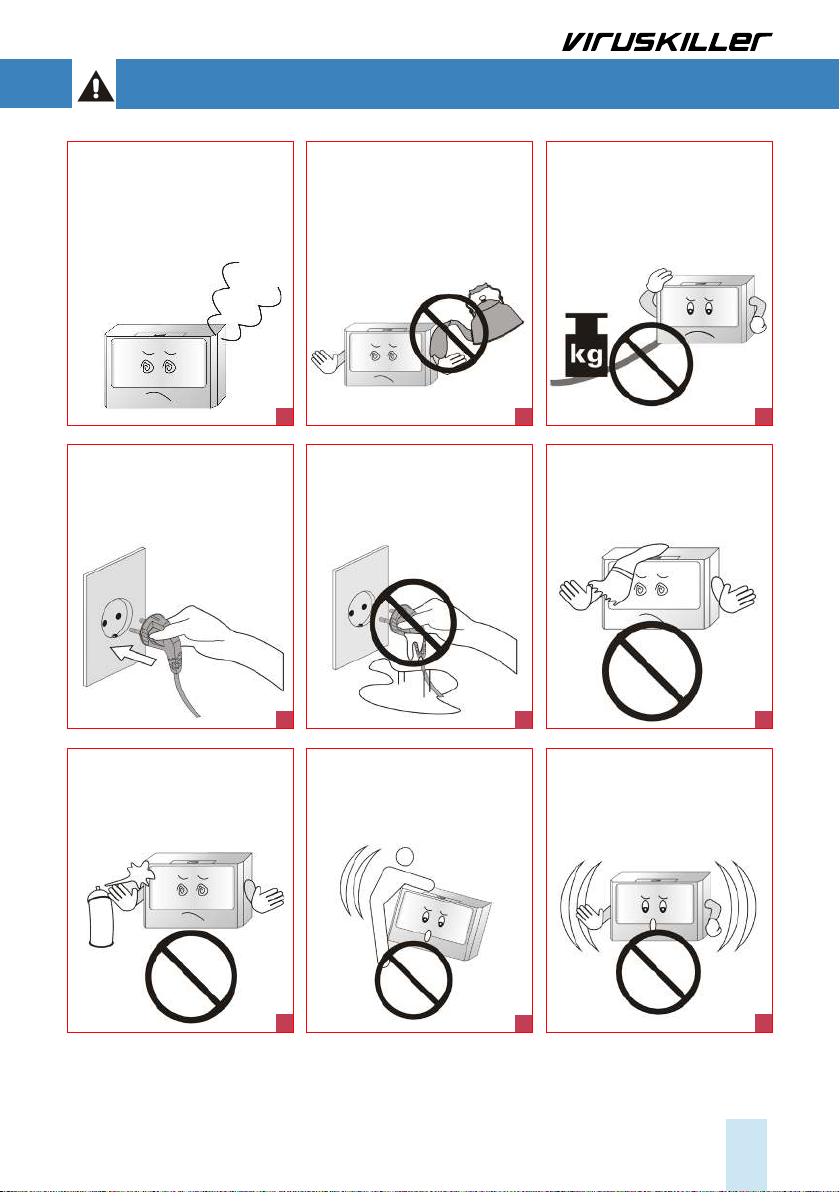
Use a dedicated power outlet.
Lightning or static electricity
could affect the circuit and may
cause a re or damage the unit.
To avoid this, plug the unit into
a dedicated, grounded outlet.
Do not alter or modify the plug
or cord of this unit as it could
cause a re or an electric
shock.
To protect against a risk of
electric shock, do not immerse
any part of the system in water
or in any other liquids.
Do not attempt to repair or
replace any part of this equip-
ment unless it is specically
recommended in this manual.
All other services should be re-
ferred to a qualied technician.
Plug the unit into a 220V AC
outlet only, if unsupervised, it
may cause an electric shock.
Use the proper power cable
and outlet, do not over-load
the outlets with several cords
simultaneously.
Keep the product away from
inammable gases, liquids, or
other combustible substances,
as this could cause an explosion.
220V
10
13
16
19
11
14
17
20
12
15
18
21

7
KEY PARTS AND COMPONENTS
Display and monitoring
Filter case
Remote control sensor
Display and monitoring
Power button ON/OFF Fan speed
Mode
(mood lamp)
Name Function
Remote Control
Sensor
Point your remote control at the sensor in order to use your remote operate the
unit.
Display and
Monitoring
Changes the information displayed on the LED in the following order: UV Lamp
Time, Current Temp, Fan Speed.
Power button
ON/OFF
To switch the unit ON/Off. You will hear a beep sound.
Fan Speed Hold the “Up” button down to increase the fan speed. Hold the “down” button
to decrease the speed. Fan speeds: FAN 1 (Quiet), FAN 2 (Normal), FAN 3 (High
Speed).
Mode
(Mood Lamp)
Hold the “lamp” button down for a few seconds in order to switch the LED lights
ON/OFF.
THE UNIT
DISPLAY AND MONITORING

8
1) Power On/Off
7) Mood Lamp On/Off
4) Mode
5) Timer -
6) Timer +
2) Fan Speed Up
3) Fan Speed Down
No Name Function
1) Power ON/OFF To switch the unit ON/Off. You will hear a beep sound.
2) Fan Speed Up Increases the fan speed. Fan speeds: FAN 1 (Quiet), FAN 2 (Normal),
FAN 3 (High Speed)
3) Fan Speed Down Decreases the fan speed.
4) Mode Changes the information displayed on the LED in the following order:
UV Lamp Time, Current Temp, Fan Speed
5) Timer (-) Sets a working time for the unit. The unit will stop after the specied
time has passed.
6) Timer (+) Sets a working time for the unit. The unit will stop after the specied
time has passed.
7) Mood Lamp ON/OFF Used to switch the blue LED Lamp ON/OFF on the unit.
REMOTE CONTROL

9
CLEANING THE PRE-FILTER
REPLACING THE SIDE CARBON FILTERS
Ensure that the unit is switched OFF and unplugged.
We recommend you check the pre-lter regularly
and clean it on a weekly basis. The plastic pre-lter
is reusable, to clean it follow the procedure below:
a) Open the handle at the top of the unit ①. Gently
slide the lter case out of the top of the unit ②.
b) Slide out and separate the pre-lter ③from the
HEPA lter ④. Ensure you have removed the
HEPA lter before washing the pre-lter.
c) Clean the pre-lter by using a vacuum cleaner.
Cleaning with warm water is also possible, however
allow the lter to dry completely before reinstalling.
You can now put the lters back into the case and
place this back into your VK 401. Make sure that
the carbon part of the lter is facing the back on
the unit. Close the lter handle, and the unit can be
switched back on.
CLEANING AND MAINTENANCE
The HEPA and Carbon lters are not reusable and should be replaced. Please contact your distributor
to purchase replacement HEPA and Carbon lters. Depending on the levels of pollution, the lifetime
of the HEPA lter may be longer or shorter than the recommended use times below:
Ensure that the unit is switched OFF and unplugged, unscrew and open the side lter door ⑤and
replace the carbon lter inside, then close the door, reinsert the screw and tighten.
1
2
34
5
Reactor cell (hrs) 8000 HEPA lter (hrs) 2000 Carbon lters (hrs) 6000
UVC lamps

10
Replacing the HEPA lter
a) Open the handle at the top of the unit ①.
Gently slide the lter case out of the top of the unit ②.
b) Slide out and separate the pre-lter ③ from the HEPA lter ④
c) Safely dispose of the old lter by placing it in a bag and sealing it.
d) Replace with the new HEPA lter
e) Place the lters back into the unit. Make sure that the carbon part of the lter is facing the back on
the unit. Close the handle, and the unit can be switched back on.
f) Press and hold the “up” switch on the unit for 14 seconds, to reset the lter warning timer. Now your
unit is ready for the next 2000 hrs.
The HEPA lter is not reusable and must be changed after 2000 hours of
use. The display panel will indicate a “FILt” warning. In order to change
the HEPA lter refer to Figure 1, and follow the instructions below:
1
2
34

11
REPLACING THE REACTOR CHAMBERS
In order for the VK 401 to remain functional the reactor chambers must be replaced every 8000 hrs.
Your unit will indicate that a change is required, “-001” displayed on the LCD.
1. Switch off, and unplug the unit.
2. Remove the 12 screws at the back of the unit.
5. Remove the 4 corner screws out of both the
chamber mountings, being careful to ensure
that the earth wire (yellow) closest to the switch-
board is detached and remains intact.
6. Remove the old reactor chambers and replace
with the new chambers which are already linked
together, then return the 4 screws to the corners
of each chamber, ensuring that the earth wire is
reconnected to the screw closest to the circuit
board, and then connect the new reactor cable
to the circuit board.
7. Close the unit carefully making sure that no
wires are trapped or damaged, return the 12
screws to the back of the unit.
8. Now switch your VK 401 back on, press and
hold the down button for 14 seconds, to reset the
warning timer. Now your VK 401 is ready for the
next 8000 hours.
3. Place the unit on its back, and carefully
lift open the front of the unit.
(make sure no wires are disconnected
when lifting the front cover)
4. Remove the black and white cable linked to
the reactor chambers. (marked J5 on the PCB)
earth wire

12
ERROR MESSAGES
Reactor Cell change
UV Lamp malfunction
Circuit overheat error
Fan error
The lifespan of the Reactor Cell is 8000 hours of use. When this time has passed,
the timer on the unit will display with a minus (-). When you see this warning
message, it is time to replace the Reactor Cell.
This is an error message that refers to a malfunction of the UV lamps. Turn the
unit off and contact customer service.
This is an error message that refers to a malfunction of the UV lamps. Turn the
unit off and contact customer service.
This error indicates that the fan is not working properly. Turn the unit off and
contact customer service.
1
2
3
4

13
TROUBLESHOOTING
Before you call for service, review this list. It may save you time and expense. This list includes co-
mmon occurrences that are not the result of defect in workmanship or materials.
Problem Possible cause Solution
The product
will not turn on
The plug is not properly insert-
ed in the grounded outlet.
Plug the device into a working grounded
outlet.
The remote control is out of
battery power
Replace the batteries according to the
polarity.
The voltage of the AC outlet is
too low
Make sure you plug the unit into its dedi-
cated, grounded 220 AC outlet.
Weak airow and
noise from the
product.
The pre-lter has accumulated
too much dust.
Clean the pre-lter to avoid this problem
Also change the HEPA lter when due.
The timer preset
does not work.
The timer function has not been
activated.
Set the timer, according to the instruc-
tions in this manual.
The air purifying
function does not
work properly.
The indoor air is heavily
contaminated
The room requires ventilation.
The pre lter is blocked Clean the pre lter.
The HEPA lter is blocked Replace the HEPA lter.
The room is too large for the
unit
Select the right Viruskiller according to
the room size.
The airow is restricted Make sure there is enough clearance
around the product and that the air inlet
and outlet of the unit are unobstructed.
Strange smell is
emitted from the
device.
New product odour The antimicrobial coating of the reactor
cell might release a small amount of
harmless odor. It should disappear in
one to two weeks.
Moist lters When cleaning the pre-lter with water,
make sure it is completely dry before
reinstalling.
The product has been used in
environments with a high con-
centration of food odours.
Food odors are oily and can penetrate
into the lter or the sterilizing module.
Use proper ventilation.
The product has been used
in environments with a high
concentration of smoke.
In areas emitting too much smoke, the
performance of the sterilizing module
may be affected. Use proper ventilation.

14
In this manual, you will nd a card containing details of your limited warranty. Please contact your
distributor if you encounter issues with your unit or to procure replacement lters or reactor cham-
ber when these reach their end of life.
Damage or malfunction caused by negligence, abuse, unauthorized repairs or use not in accordance
with the User Guide will not be covered. All warranties are rendered void and the cost of repair will be
payable by the user in the case of damages caused by:
- putting in foreign objects (such as water, liquids, fragrance oils, toys etc.) in or out of the unit;
- transportation or handling;
- use of products such as benzene or thinners;
- incorrect power supply or output voltage;
- breakdown or loss of part caused by unauthorized disassembling or modications;
- repair or replacement undertaken by unauthorized persons
- non-adherence to the instructions provided in this user guide, and as given by the local customer
service center;
- careless or improper use; and
- caused by operating the product in a corrosive or moist environment.
CUSTOMER SERVICES
The company reserves the right to make changes to the design and specications of the product
without prior notice.
Description Air Sterilizer
Brand VIRUSKILLER
Model No VK 401
Max. Elec.
Consumption 120 watt
Net Weight 12.9 Kg
Net Dimensions 365 H x 165 D x 581 W mm
Airow (CFM) 70 – 141
UVC Lamps 8
TiO2Hexagon
Filters ~40
Power cord length 1.2 m
SPECIFICATIONS


16
Sales & Design: First Floor, Columbia Mill, Bedford Street, Bolton, BL1 4BA
Tel : +44 (0)1204 238823,
E-mail: inf[email protected],
Manufacturer: INBair Korea LTD
3~4F, 72, Jomaru-ro 411 Beon-gil, Bucheon-si, Gyeonggi-do, South Korea
E-mail: inbair01@naver.com, www.inbair.com
Made in Korea | Designed in England
World Leading Air Sterilization Equipment
This manual suits for next models
1
Table of contents
Other Radic8 Steriliser manuals
Popular Steriliser manuals by other brands

Lena Lighting
Lena Lighting UV-C STERILION 72W Installation instruction

Bubbli
Bubbli BBSTERMICRA quick start guide

Light Progress
Light Progress UV-FLOW C-NX Series manual

Lena Lighting
Lena Lighting UV-C STERILION 36W Installation instruction

Philips AVENT
Philips AVENT Avent SCF922 user manual

Philips
Philips SCF284/02 Service manual