TVC NFM3 User manual

+44 (0)1493 443800
www.tvcalx.co.uk
The Validation Centre (TVC) Limited
Unit 15, Brinell Way, Harfreys Industrial Estate, Great Yarmouth, Norfolk,
NR31 0 U, UK.
NFM3
Nozzle Flow Meter 3 including Dual Nozzle Model
Instruction Manual
V1.2

Contents
1.0 Description 3
1.1 Items supplied 3
1.2 Connectors and controls 4
2.0 Operational instructions 5
2.1 Operational warnings 5
2.2 Powering up the unit 5
2.3 Gas selection 6
2.4 Flow measurement 7
2.5 Selecting measurement units (NFM3 Advanced only) 8
2.6 Peak reset 9
2.7 Data logging (NFM3 Advanced only) 9
2.7.1 Mode 1 9
2.7.2 Mode 2 10
2.8 Viewing logged les (NFM3 Advanced only) 12
2.8.1 Transferring logged les into MS-Excel report 13
2.8.2 Surge le example 14
2.8.3 Removing logged les 14
2.9 Operational ow charts 15
2.9.1 Flow chart 1: NFM3 Standard 15
2.9.2 Flow chart 2: NFM3 Advanced ‘Mode 1’ 16
2.9.3 Flow chart 3: NFM3 Advanced ‘Mode 2’ 17
3.0 Dual Nozzle Model 18
4.0 Battery charging 18
5.0 Additional information 19
5.1 Specication 19
5.2 Calibration 19
5.3 Disposal 19

12
5
6
1.0 Description
1NFM3
2Battery charger
316mm nozzle
419mm nozzle
522mm nozzle
6Nozzle extension hose
7NFM3 to TVC Welding Data Logger interface lead (optional)
8NFM3 to PC USB interface lead (NFM3 Advanced model only)
3
1.1 Items supplied
The NFM3 is supplied with the following:
3, 4 & 5
7
8

9
87
1
2
3
4
5
6
4
1.2 Connectors and controls
1Quick-t ow inlet
2Display screen
3‘Reset’ button (reset peak gas ow value)
4‘Log’ button (for use with TVC weld monitors)
5‘Up’ button
6‘Down’ button
7USB / Welding Data Logger output connector
8Charger input
9On / O Switch

2.0 Operational instructions
5
The following MUST be read before attempting to use the NFM3:
1 The NFM3 is designed for use on Inert Arc Welding Shielding
and Back Purging gases only.
2Always ensure that the wire feed drive wheels are slackened
o so that welding wire cannot be fed through the NFM3.
3When using on equipment with High Frequency Arc
Starting, always ensure that the HF is turned o.
2.1 Operational warnings
2.2 Powering up the unit
Switch the On/O switch to the ‘On’ position.
The LCD will illuminate and the software version number together with the
model type will be displayed for a few seconds the screen will then revert
to the standard display layout.
NFM3 Standard:
Start Up screen
NFM3 Standard:
Main screen

6
2.3 Gas selection
The NFM3 has been programmed with nine gas mix selections, these are:
•Argon (Ar)
•Carbon Dioxide (CO2)
•Argon/CO2 Mixes (Ar-CO2)
•Nitrogen (N2)
•Argon/Helium Mixes 0 to 10% (Ar-He 10%)
•Argon/Helium Mixes 10 to 30% (Ar-He 30%)
•Argon/Helium Mixes 30 to 50% (Ar-He 50%)
•Argon/Helium Mixes 50 to 70% (Ar-He 70%)
•Argon/Helium Mixes 0 to 100% (Ar-He 100%)
NFM3 Advanced:
Start Up screen
NFM3 Advanced:
Main screen
The NFM3 has a ‘button-lock’ feature to prevent accidental button presses
which may change the gas selection. To access the gas selection area,
press and hold the ‘Up’ button for 3 seconds.
Once the buttons are unlocked and functioning, use the ‘Up’ and ‘Down’
buttons to scroll between the available selections. The selected gas is
displayed at the bottom of the screen.

7
NFM3 Standard
NFM3 Advanced
2.4 Flow measurement
Select the required size nozzle and connect it to the NFM3 quick-
release tting. If required, use the extension hose.
Insert the arc welding torch nozzle into the NFM3 nozzle, ensuring
a good t. Make sure the NFM3 is unit switched ‘On’ and the correct
gas type is selected.
Press the ‘Gas Purge’ button on the arc welding set. Once the ow
has stabilised, read the ow in Litres per minute on the NFM3
screen. Once the gas stops owing, the NFM3 screen will revert to
the small screen and display the peak ow, this is indicated with a
‘PK’ next to the ow reading.

8
NFM3 without extension
NFM3 with extension
2.5 Selecting measurement units (NFM3 Advanced only)
The NFM3 should be factory-set to measure in either Metric or Imperial
units, however, should this need to be adjusted this can be done via a
computer.
When the NFM3 is connected to your computer it will appear as a
removable drive in the Windows ‘My Computer’ page. Double-click the
drive icon to open the drive and nd the NFM3 les.
Double-click on the le ‘TVC-Handheld-Date-Setter.exe’. The following
software window will open on your PC.

9
Follow the instructions and ensure that the correct measurement units box
is ticked (Item 4, above).
The date and time can be adjusted using this also (Item 5, above).
2.6 Peak reset
To reset the peak ow before taking another reading, press the ‘Reset’
button. The peak ow will immediately reset to zero, ready for the next
reading to be taken.
2.7 Data logging (NFM3 Advanced only)
The optional data logging facility records ow results and surge data on
the NFM3’s internal memory. Recorded data is downloaded from the
NFM3 via USB connection for direct import into the included data viewing
and reporting software.
There are two modes for data logging:
Mode 1 Quick ‘screen print’ of results.
Mode 2 Logs gas over a set time, taking a gas reading
every 20 milliseconds.
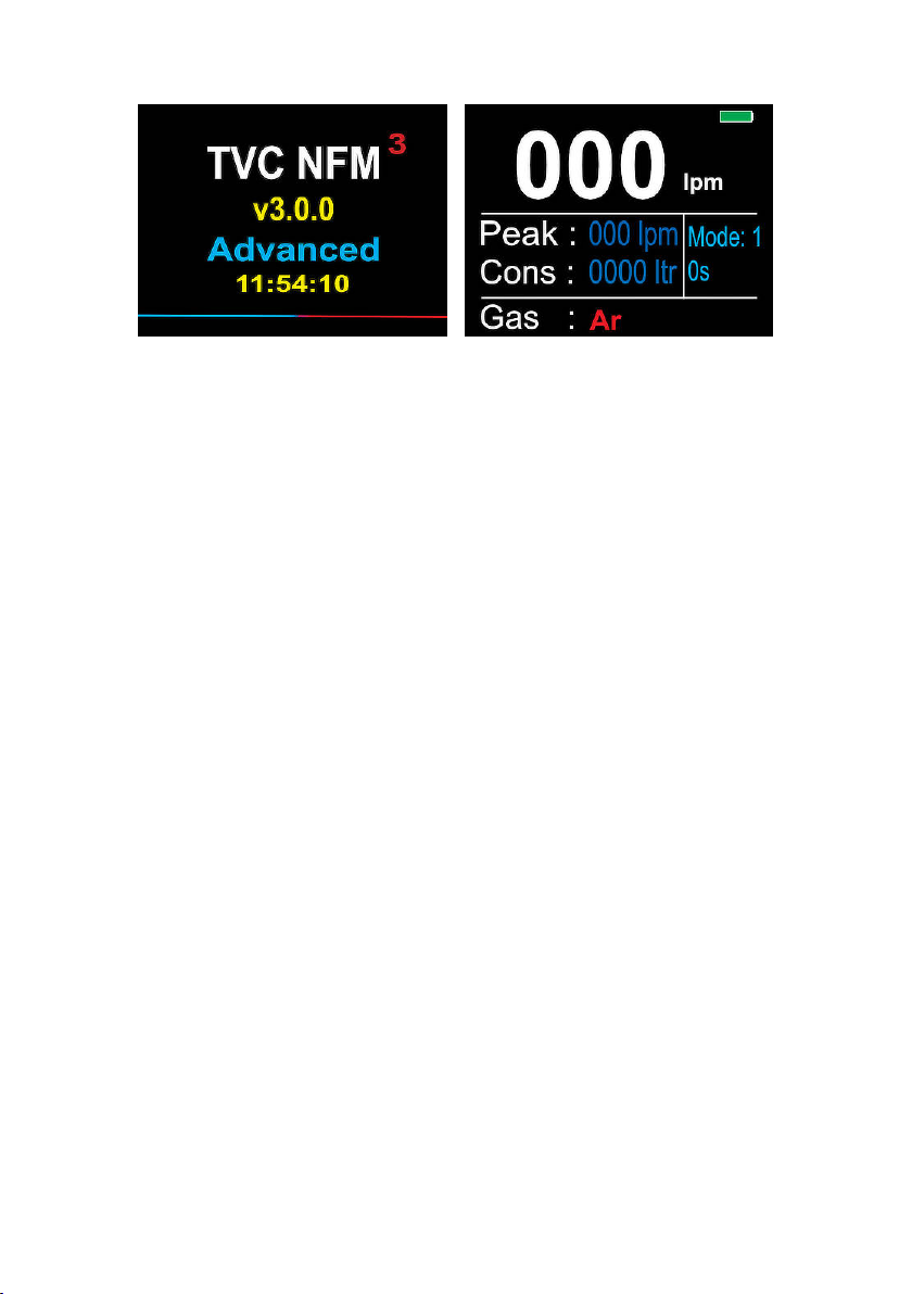
2.7.1 Mode 1
1Switch on the NFM3 Advanced unit.
2By default, the NFM3 is already in ‘Mode 1’. This provides
a quick ‘screen print’ of the results.
3Once the gas ow has been read, the screen will display
the average gas ow, peak ow and gas consumed. To log
this on the NFM3’s internal memory, press the ‘Log’ button.

10
2.7.2 Mode 2
To set up the data logging function over a specic period, press the ‘Reset’
button until the setup screen is displayed.
Using the ‘Up’ and ‘Down’ buttons, set the data logging duration.
Press ‘Reset’ to return to the main screen. The unit will now be in ‘Mode
2’.

11
Press the ‘Log’ button to set the NFM3 ready to record. A green bar will
appear at the top of the screen to show the unit is ready to log.
The NFM3 will only start logging when a gas ow has begun. The
progress bar at the top of the screen will turn black. This bar will indicate
how much time is remaining to log the gas, lling with blue as it logs. When
the bar is fully blue, the logging has nished.
When the logging is complete, the progress bar will ash red, then
disappear.

12
After reading the gas ow for the desired time, the screen will display the
average gas ow, peak and gas consumption.
2.8 Viewing logged les (NFM3 Advanced only)
To view the recorded data on a laptop or PC, connect the NFM3 using the
USB cable provided.
The NFM3 will display the following screen whilst it is connected.

13
When the NFM3 is connected to a laptop or PC, it will appear as a
removable drive in the MS-Windows ‘My Computer’ page. Open the drive
by double-clicking on it and nd the NFM3 les.
All logged gasses are stored under folders labelled by the date (Day,
Month, Year, e.g. 01042014). Open one of the folders to view the logged
gasses for that day.
LOG.CSV contain all the gas screen prints taken whilst in ‘Mode
1’.
.TXT contain logged gasses while in ‘Mode 2’. Each TXT
le is labelled using the time the gas was logged
(Hour, Minute, Seconds, e.g. 123846).
2.8.1 Transferring logged les into MS-Excel report
TVC provide two MS-Excel templates which can be used to open les and
display the logged gas in a report. Both templates operate in the same
manner making them easier to use.
The ‘Log File Reporter’ template should be used to open log les, i.e., gas
screen captures whilst in ‘Mode 1’.
The ‘Surge File Reporter’ template is used to open .TXT les captured in
‘Mode 2’.

14
2.8.2 Surge le example
Open the ‘Surge File Reporter’ template.
Once opened, click the ‘Load’ button to open a Windows le browser. Go
to the drive and select one of the logged TXT les.
The template also provides gas costing. The gas costs can be adjusted
from the second sheet, ‘Gas Costs’, found on the sheet tabs at the bottom
of the MS-Excel document.
Click the ‘Open’ button. The template will now open the le and display
the gas data it has found.
To keep the information as a MS-Excel document, re-save the document
under a dierent name.
2.8.3 Removing logged les
Files on the NFM3 are like normal MS-Windows les. This means you can
remove or delete them as you normally would.

15
2.9 Operational ow charts
2.9.1 Flow chart 1: NFM3 Standard
Power On
Select gas by using 'Up' and 'Down'
buttons.
To reset the peak ow, press the
‘Reset’ button.
Insert welding torch nozzle in to the
NFM3 nozzle and purge gas. NFM3
will display the gas ow in LPM whilst
gas is owing. The unit will display
the peak ow achieved when the gas
stops owing, and the gas consumed.

16
2.9.2 Flow chart 2: NFM3 Advanced ‘Mode 1’
Ensure 'Mode 1' operation is selected.
To set 'Mode 1', press and hold the 'Reset'
button for 5 seconds. The main screen will
change to the setup screen.
For 'Mode 1' operation, use the 'Up'/'Down'
buttons to set the log duration to 000s.
To exit the setup screen, press the 'Reset'
button.
Insert welding torch nozzle in to the NFM3
nozzle and purge gas.
Gas ow will display in LPM whilst gas is
owing. The unit will display the peak ow
achieved when the gas stops owing, and
the gas consumed.
To save the displayed data, press the 'Log'
button. Reset the displayed data by
pressing the 'Reset' button.
Power On

17
2.9.3 Flow chart 3: NFM3 Advanced ‘Mode 2’
Ensure 'Mode 2' operation is selected.
To change from 'Mode 1' to 'Mode 2', press
and hold the 'Reset' button for 5 seconds.
The Setup screen will be displayed.
For 'Mode 2' operation, use the 'Up'/'Down'
buttons to set the log duration from 005s
to 060s.
To exit the setup screen, press the 'Reset'
button.
Select gas by using 'Up'/'Down' buttons.
Press the 'Log' button. A green bar will
appear at the top of the screen. The NFM3
is now ready to record the gas surge.
Insert welding torch nozzle in to the NFM3
nozzle and purge gas.
Gas ow is displayed in LPM whilst gas is
owing. The unit will display the peak ow
achieved when the gas stops owing, and
the gas consumed. When the gas ows,
the green bar will change to blue and
move across the screen for the pre-set log
duration.
Once the surge data is recorded, the bar
will turn red and then disappear. Reset the
displayed data by pressing the 'Reset'
button.
Power On

18
4.0 Battery charging
The NFM3 uses a rechargeable 7.2 Volt Lithium-Ion battery which lasts for
approx. 8 to 10 hrs. When the battery level reaches 000%, the unit should
be recharged using the supplied battery charger.
3.0 Dual Nozzle Model
The NFM3 Dual Nozzle Model features an additional argon-only nozzle.
The NFM3 Dual Nozzle Model has a ‘gas lock’ feature. To stop the gas
being accidentally changed, the ‘Up’ / ‘Down’ buttons are disabled.
To enable the buttons, press the ‘Up’ button for 3 seconds. A red arrow
will appear on the display and enables the gas to be changed.
After a few seconds of no further button presses, the arrow will disappear,
and the ‘Up’ / ‘Down’ buttons are locked again.

19
Yellow LED Green LED Mode
O O Mains disconnected
On On Battery charging
O On Mains connected; battery charged, or
battery disconnected
5.0 Additional information
5.1 Specication
Range 5 to 100 LPM (Argon)
Accuracy ±5% reading ± 1 Digit
Transducer Type Turbine
Battery Li-Ion 7.2V 2.6Ah Rechargeable
5.2 Calibration
All units are supplied with valid and traceable calibration
certication.
NB: Only use the battery charger supplied by TVC for charging the
NFM3!
Insert the battery charger plug into the charging input socket. Connect the
battery charger to a suitable mains supply. The battery will take between
1.5 to 2 hours to fully recharge. The unit should be disconnected from the
battery charger once fully charged.
The charge cycle and LED indications for the battery charger are listed
below:
TVC recommend that the unit is returned to TVC or a TVC-approved
distributor for recalibration and service at least once every 12 months.
5.3 Disposal
To meet our obligations under the WEEE directive, we have
a collection point for the recycling of this product once it has
reached the end of its normal working life. In these
circumstances, please contact us for further instructions.
For further information on equipment calibration or disposal
please contact TVC.
Other manuals for NFM3
1
Table of contents
Other TVC Measuring Instrument manuals
Popular Measuring Instrument manuals by other brands

Endress+Hauser
Endress+Hauser Prosonic M FMU40 Brief operating instructions

SICK
SICK InspectorP Rack Fine Positioning operating instructions

THORLABS
THORLABS S1FC635 user guide

Flybox
Flybox Omnia57 ALTI-VARIO Installation and user manual

Endress+Hauser
Endress+Hauser Proline Promag 55 PROFIBUS PA operating instructions

ADS
ADS Intrinsically-Safe TRITON+ Installation, operation and maintenance manual