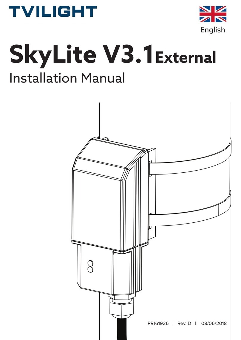
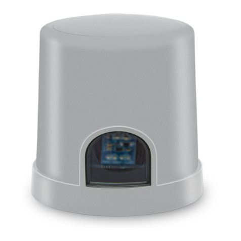
TVILIGHT OPENSKY Zhaga IoT User manual

English
OPENSKY
Zhaga IoT
Installation Manual
PR166202
Copyright Tvilight B.V. | PR 00-1662-02 | Rev. D | 24/01/2021
TVILIGHT PROJECTS BV / Beechavenue 162-180, 1119 PS, Schiphol-Rijk, the Netherlands

R 166202 | Rev. D | Page 2 of 13
www.tvilight.com
TVILIGHT PROJECTS BV / Beechavenue 162-180, 1119 PS, Schiphol-Rijk, the Netherlands
ATTENTION:
In order to function properly, OPENSKY Zhaga IoT must be
connected to a dimmable DALI driver/ ballast (preferably D4I
or SR compliant).
NOTE: Some dimmable drivers/ballasts must be
programmed/set to DALI mode. Also, select the correct
configuration (i.e. DALI) from the CMS. If this has not been
done, OPENSKY Zhaga IoT will not be able to dim the
connected armature.
DALI (logarithmic) dimming mode is recommended.

In box:
PR 166202 | Rev. D | Page 3 of 13
In box:
OpenSky Zhaga IoT
50.83 mm
15.87 mm
Beechavenue 162-180, 1119 PS, Schiphol-Rijk, the Netherlands
Designed in the Netherlands. Assembled in PRC.
Zhaga OLC device comes
with two QR Code labels:
1. Please stick one label on
the street light luminaire.
2. Please stick the second
label on the street pole,
preferably inside the
junction box.
QR Code needs to be
scanned once using Tvilight
Scan & Go App (please see
the instructions below)
Input: 18-30 Vdc
Output: 0 - 10V/ DALI/ SR/ D4I
RF: EGPRS/LTE Cat M1/Cat NB2
ta : -40˚C... +70˚C
50.83 mm
15.87 mm
Zhaga IoT
740215000AC

R 166202 | Rev. D | Page 4 of 13
www.tvilight.com
Register device to CityManager (CMS)
1. Download Tvilight Scan & Go from Apple iOS App Store or Android PlayStore.
2. Login with your Username and Password.
3. Use the ‘Add device’ function in the Scan&Go app to add the device to CityManager.
4. The Device Name (OpenSky Zhaga IoT), Serial Number/ QR Code (UID) and Com-
ments can be added manually.
5. The Device Serial Number can also be added using the Scanner function which is
activated by tapping the camera icon in the app.
6. For more information on how to use Scan&Go app, please visit:
https://www.tvilight.com/scan-go/
7. To create your user account, please email helpdesk@tvilight.com. Please add your
customer name, project reference, and purchase order number.

R 166202 | Rev. D | Page 5 of 13
www.tvilight.com
Press OpenSky Zhaga IoT onto the Zhaga Receptacle and twist to lock in place.
2. Connect OpenSky Zhaga IoT
1. Remove Sealing Cap from the Zhaga Receptacle
NOTE: The receptacle, and threfore the OpenSky Zhaga, must be mounted on the
top side of the luminaire.

R 166202 | Rev. D | Page 6 of 13
www.tvilight.com
Ensure that the Product and Pole ID Labels match.
3. Apply Pole ID Label to the pole
Beechavenue 162-180, 1119 PS, Schiphol-Rijk, the Netherlands
Designed in the Netherlands. Assembled in PRC.
Input: 18-30 Vdc
Output: 0 - 10V/ DALI/ SR/ D4I
RF: EGPRS/LTE Cat M1/Cat NB2
ta : -40˚C... +70˚C
Zhaga IoT
740215000AC
740215000AC
1 m

R 166202 | Rev. D | Page 7 of 13
www.tvilight.com
A1. Mounting
NOTE: The content in this Appendix is derived from the TE LUMAWISE Endurance
S Connector System Application Specification 114-133074 (12 May 17 Rev 3). For
more detailed installation instructions consult the latest TE Application Specification
document.
A surface shall be provided on luminaire housing that is ideally flat. If a flat surface
is not possible a secondary possibility is to have a flat surface in one direction and
a minimum radius in the other of 500mm to mount the receptacle. To provide a
water tight mounting seal, the luminaire surface must be free of dirt, debris, or burrs.
Sealing gasket provided with the receptacle assembly must be used.
Receptacle can be used on a luminaire housing thickness between 1.5mm to 6.0mm.
When mounting receptacle assembly, it must not rotate during locking washer and
locking nut application. Torque mounting nut within the range of 1.8 to 2.4 N-m using
a 27mm hex socket.
The location of the hole must be on the top side of the luminaire.
Appendix : Zhaga Receptacle Mounting and
Wiring Specification
Receptacle assembly with
pre-installed gasket
Top Side of the
Luminaire housing
Mounting hole
Mounting nut
Lock washer

R 166202 | Rev. D | Page 8 of 13
www.tvilight.com
NOTE: Variations to the recommended mounting hole are possible but must be verified by the end user to ensure they
do not result in excessive movement of the receptacle assembly during mounting or use. Excessive movement could
result in reduced system performance. An absolute maximum hole diameter of 22.0mm should be used.
The recommended mounting hole can be seen below. Refer to product drawing for
additional details.
A2. Mounting Hole Pattern

R 166202 | Rev. D | Page 9 of 13
www.tvilight.com
Receptacle assembly with
pre-installed gasket
Pun
Number
Function
1 +24V power supply
2* Negative pole for DALI or DALI based protocol
and shared GND return for 24V power supply
3 Positive pole for DALI or DALI based protocol
4 LSI sensor input
The receptacle is wired on the bottom side of the assembly; access from the inside of
the luminaire. Wire entry locations are labelled 1, 2, 3, and 4. Corresponding contact
designations are marked the same on the module bases for PCB alignment.
A3. Wire Locations
* Please ensure to connect the DALI+ and DALI- wires
correctly. DALI- is shared with the Device GND line.

R 166202 | Rev. D | Page 10 of 13
www.tvilight.com
The receptacle assembly will accept 16 through 20AWG solid and 18 through 20AWG
stranded tin-dipped copper wire only. The table in Figure 5 provides wire selection
for the Poke-In Connectors.
A4. Wire Selection and Preparation
Recommend Wire
Wire Size Wire Type Insulation Diameter Strip Length
16 AWG Solid
ø2.95 MAX
ø1.90 MIN
11.0 ±1.0
18 AWG Solid
Stranded (tin-dipped)
20 AWG Solid
Stranded (tin-dipped)
Stranded Wire
(Acceptable only if tin-dipped)
Solid Wire
(Acceptable)
(Not Acceptable)
Insulation
Conductor
Strip
Length
Strip
Length
Bent Stripped
Wire
Burr at Cuto
Extreme Chisel Tip
Not Cut 90°
Misaligned Cutter
Tips
Poorly Prepared
Insulation
NOTE: Recommended maximum insulation diameter should be as provided in Figure 5. Wires with larger insulation
diameters will not fit within the housing’s poke-in hole insulation tunnel. Wires utilizing semi-rigid insulation are
recommended to minimize movement of the insulation along the axis of the wire. Movement of the insulation will result
in variation of the wire strip length which can lead to incorrect wire termination.

R 166202 | Rev. D | Page 11 of 13
www.tvilight.com
All wires must be pushed firmly inside the contact wire openings. The wires must be
fully inserted so that the wire insulation is inserted between three and five millimeters
into the rear of the housing.
The required wire termination depth is achieved when the wire has bottomed in the
connector housing. Connector design has an internal wire stop.
A fully inserted wire can be extracted from the receptacle using a tool and the
release tool window located on the bottom of the receptacle housing. Using tool tip
that is 0.8mm x 1.4 mm in cross section and 16.0mm long, insert it into the window
(one per wire) and open the contact beams. The wire may then be extracted from the
connector along the axis of wire insertion direction.
A5. Wire Termination
Stripped wire
inserted into
housing
Insulation
inside housing
Release tool
window
Release tool
fully inserted
Wire can be
retracted from
housing
Release tool
DANGER: Extreme caution to ensure there is no power in the system prior to insertion of wire extraction device.
Electrical shock or system damage can result if care is not taken.
CAUTION: Extraction device to be free from burrs and sharp edges to ensure no damage is done to connector
terminals.
CAUTION: A new stripped wire must be re-inserted into cavity after extraction of existing wire. DO NOT re-use
extracted wire.

R 166202 | Rev. D | Page 12 of 13
www.tvilight.com
Getting started
1. Ensure that the device is pre-registered through Tvilight Scan & Go App
2. Ensure that the device is installed properly as per the steps mentioned
previously
3. Turn ON the power
4. The device starts to initialize, and the red LED (visible inside the device
window) will flash (blink). Blinking Red LED is a good sign; it shows the
device is alive.
5. The device tries to register to the local telecom network and the green LED
will flash. It may take several minutes. First time sim card connectivity can
take between 30 minutes to 8 hours depending on your country and the
OLC location. So, please have patience!!
6. The device should now be online on CMS and the green LED will turn to
solid green. The device should now be online on CMS
7. Use your login (same as Scan & Go app) or other user account provided by
Tvilight Support Desk to login to the CityManager CMS (https://tvilight.io/)
8. You are ready and connected. Enjoy energy savings and smart
maintenance notifications!
LED status
Blinking Red Device running normally
Solid Green Connected to Server
Troubleshooting
1. If the Red LED (inside the small window) does not blink
This can be due to lack of power:
1. Please ensure to turn ON power from the circuit breaker.
2. Please check if the streetlight luminaire is working.
3. Check if the wires are properly connected.
4. Ensure that the device is locked/ properly connected on the Zhaga
receptacle

R 166202 | Rev. D | Page 13 of 13
www.tvilight.com
2 If the device shows flashing/ blinking GREEN LED (after powering
the device for at least 8 hours)
This means that the device is not able to connect to the CMS server.
This can be due to the following reasons:
1. The device is not yet registered in the Tvilight CMS. Please get it
registered using the Scan & Go app (see instructions above).
2. There is no sim card network reception on the device location.
(Please note that the sim connection can take as much as 8 hours
when used for the first time in your region.)
3. If the above steps did not resolve the issue, then please contact
3 Tried everything/ faulty device?
instructions and send the device for (RMA) replacement.
Further support
We are here for you! Please contact us at [email protected], our
preferred partner JIRA portal or https://www.tvilight.com/support/
Thank you for purchasing
TVILIGHT
We are proud of your contribution with making our world
Greener and Safer!!
This manual suits for next models
1
Table of contents
Other TVILIGHT Controllers manuals
Popular Controllers manuals by other brands

Keba
Keba Kemro K2 user manual

Sorel
Sorel XHCC Installation and operating instructions

Schischek
Schischek ExMax quick start guide

Aerotech
Aerotech UNIDEX 600 Series user guide

Precision Digital Corporation
Precision Digital Corporation PD9000 ConsoliDator+ instruction manual

Toro
Toro NO FOUND TMC-424E user guide