TWT IonGuard TWT-5C8-277-0.5 Amp User manual

Email:info@triangularwave.com • Triw[email protected] • Website:www.Triangularwave.com
TWT®IonGuard Disinfection & Purification System
Pool • Spa • HVAC Water Treatment & Conditioning
Commercial/Industrial Model#
TWT-5C8-277-0.5 Amp • TWT-5C8-278-1.25 Amp • TWT-5C8-279-2 Amp
OWNER APPLICATION & INSTALLATION MANUAL
The TWT®systems will give many years of service if sized and installed properly.
Please read all instructions carefully before assembling the system.
SEE PAGE 9-10: INSTRUCTIONS FOR THE USE OF TWT®DEPOSIT CONTROL TECHNOLOGY
If you have purchased model#
TWTDCI-5C8-377 • TWTDCI-5C8-378 • TWTDCI-5C8-379
integrated deposit control and ionization treatment system
Note: IonGuard operational instructions are the same for all listed treatment systems
Do not discard operating manual, keep in equipment room for reference
M57

Email:info@triangularwave.com • Triw[email protected] • Website:www.Triangularwave.com
TABLE OF CONTENTS
Section 1: . . . . . . . . . . . . System Description
Section 2: . . . . . . . . . . . . Operating Principals
Section 3: . . . . . . . . . . . . Installation
Section 4: . . . . . . . . . . . . System Installation Overview
Section 5: . . . . . . . . . . . . Connection of the Ionization System to the Connecting Piping
Section 6: . . . . . . . . . . . . Connection of the Ionization System to Remote Control System
Section 7: . . . . . . . . . . . . Connection of the IonGuard System to Electrical Power
Section 8: . . . . . . . . . . . . Steps to Put the IonGuard System in Service
Section 9::. . . . . . . . . . . . Adjusting the IonGuard System
Section 10:. . . . . . . . . . . . . Replacing the Ionization Electrodes
Section 11:. . . . . . . . . . . . . Trouble Shooting: IonGuard System
Section 12:. . . . . . . . . . . . . Trouble Shooting:TWT Deposit Control Technology
Product Warranty / Performance Warranty (90 Days)
To find out even more about us, and how we can help you, contact us at: Email: [email protected]
Bringing You The best in Fluid Management Solutions
Visit Triangular WaveTechnologies, Inc.’s comprehensive website,
the valuable technical resource for all involved in water and fluid management...
WWW.TRIANGULARWAVE.COM

Email:info@triangularwave.com • Triw[email protected] • Website:www.Triangularwave.com
1
SYSTEM DESCRIPTION
The Triangular Wave IonGuard Purification System is
a compact, self-contained system to kill bacteria and
algae in the water system.
The IonGuard main components are:
• Power Supply/Electronic Control Unit
•Ionization PVC “T-Housing” (Schedule 40 PVC)
• Copper/Silver Ionization Electrodes
• Power cord, electrical wires, and extra fuse.
•Copper Test Kit
Please Note: See page 9-10
For maximum efficiency, the Triangular Wave
IonGuard Purification System should be installed
with the Triangular Wave Deposit Control System.
SECTION 1
Diagram A.System installation overview
Not included:Recommend GFI be installed.
IonGuard System
IonGuard Controller
Copper/Silver
Ionization Electrodes
T-Housing
Backwash
Reaction Chamber
Optional
Deposit
Control
IonGuard
Purification System
IonGuard
Purification System
Return Line
to Pool
Water Lines
From Pools
Water
Flow
PUMP
FILTER
HEATER

Email:info@triangularwave.com • Triw[email protected] • Website:www.Triangularwave.com
2
OPERATING PRINCIPLES
The Triangular Wave IonGuard Purification System
disinfects water through a process called ionization.
That process utilizes a low voltage direct current [DC]
to place precise and minute amounts of copper and
silver ions into water systems. Copper ions kill algae
and silver ions kill bacteria. An ion is merely an elec-
tronically charged atom or group of atoms. An atom
acquires this charge by gaining or losing electrons.
Negatively charged electrons are one of the three
major subatomic particles; the others being protons,
which have a positive charge, and neutrons, which
have no charge.
Ions in the Triangular Wave system are positively
charged; algae, bacteria and other particles in the
water are negatively charged. The positive to
negative attraction allows the ions to attach to the
organisms, penetrate their cell walls and kill them.
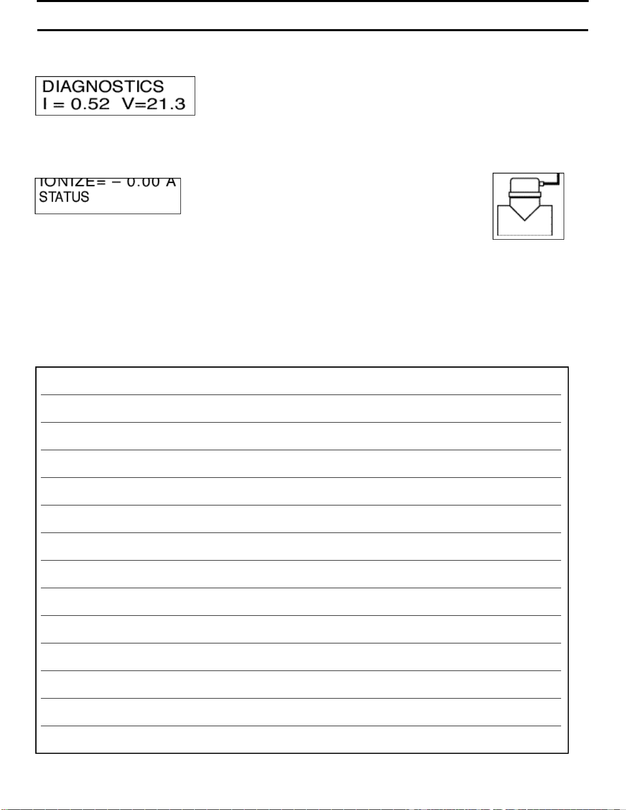
The IonGuard Purification System is an electrolytic
copper/silver ion generator.The system units contain
specifically cast copper/silver alloy electrodes. These
electrodes are mounted in a PVC housing designed
specifically for easy access.
When the system is used in conjunction with a filter,
the dead bacteria with the silver ion attached to it will
be large enough for the filter to remove. Normal filter
backwashing will then remove the dead particles.
The criteria for copper and silver in water are as
follows:The EPA standard for drinking water is 1.0
ppm (parts per million) maximum for copper and 50
ppb (parts per billion) maximum for silver.The system
is programmed so that a water test showing 0.25
ppm to 0.35 ppm copper automatically provides the
proper ratio of silver. This will produce drinking water
quality in any water system treated. The system
requires no chemicals in their function of controlling
algae and bacteria.
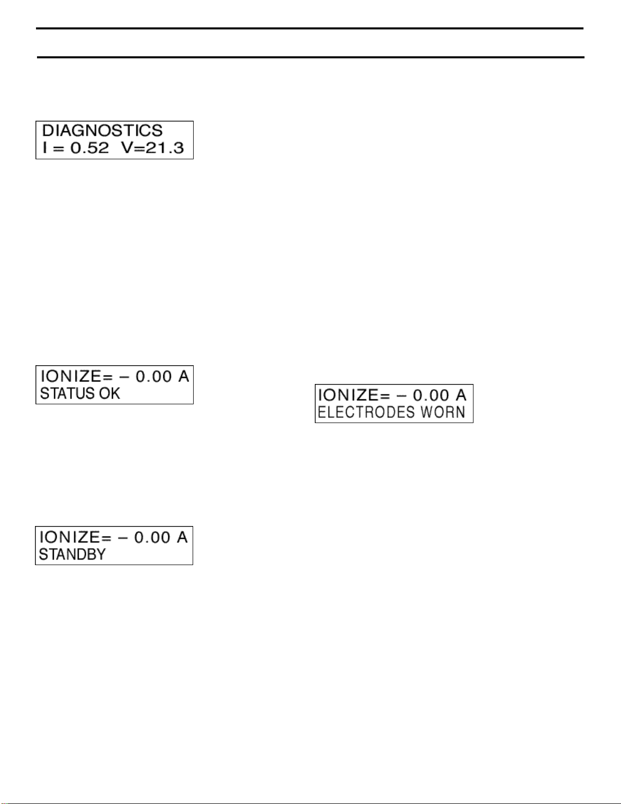
A “current source” generator powers the IonGuard
Purification System. “Voltage source”generators
power other ionization units. In all ionization units,
copper and silver ions plate off of the electrodes and
enter the water. Over time, the electrodes will
become smaller, and the gap between the electrodes
will become larger. The current source generator will
automatically compensate for the change in gap size;
while the voltage source generators must be manual-
ly inspected and adjusted. The current source gener-
ators on the Triangular Wave IonGuard System offers
trouble free operation.
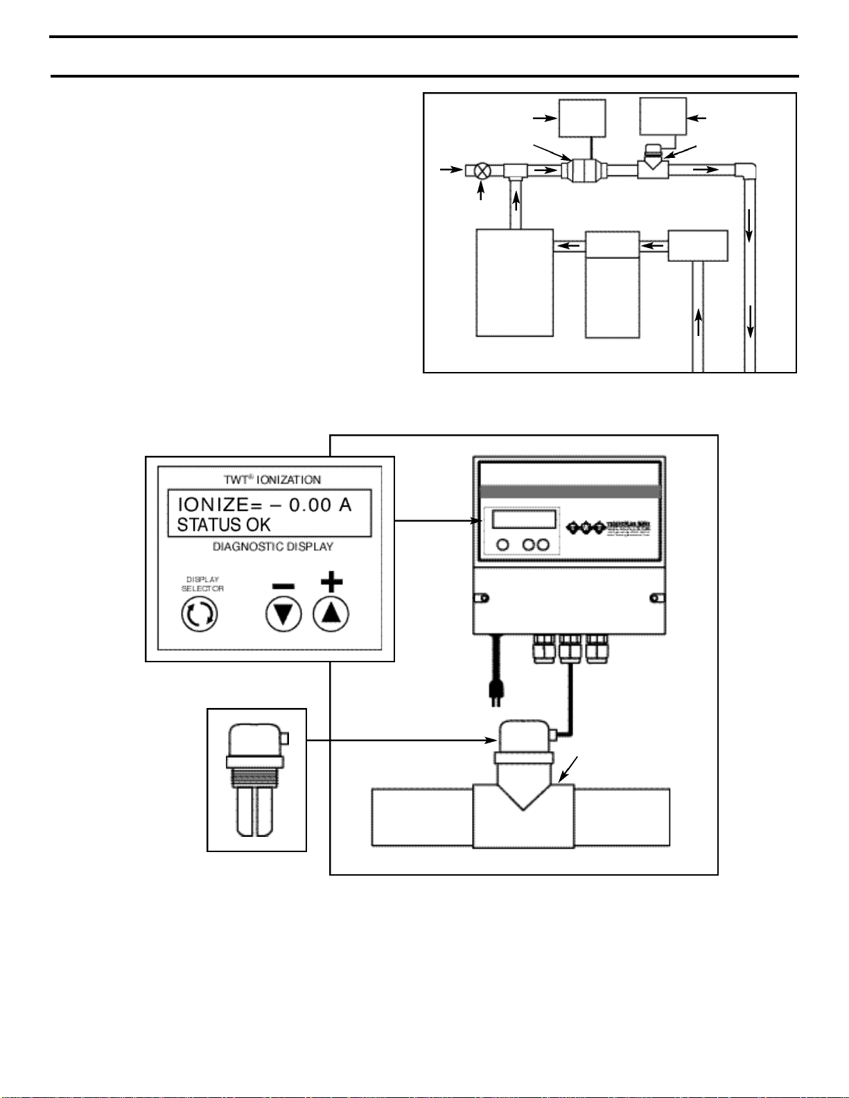
We recommend that the IonGuard Purification
System be installed downstream of a Triangular
Wave Deposit Control System. The Deposit Control
will keep the IonGuard System electrodes free of
scale and other deposits for more effective results.
And, at the same time, the Deposit Control System
will help eliminate scale and biofilm deposits through
the entire water system. (see diagram A Page 1)
Without the Triangular Wave Deposit Control System
in place, the ionization electrodes may develop either
a layer of scale or oxidation. In either case, it is
necessary to periodically clean the electrodes with
an acid solution. The Deposit Control System
Reduces the need for periodic cleaning.
INSTALLATION
SECTION 2
SECTION 3
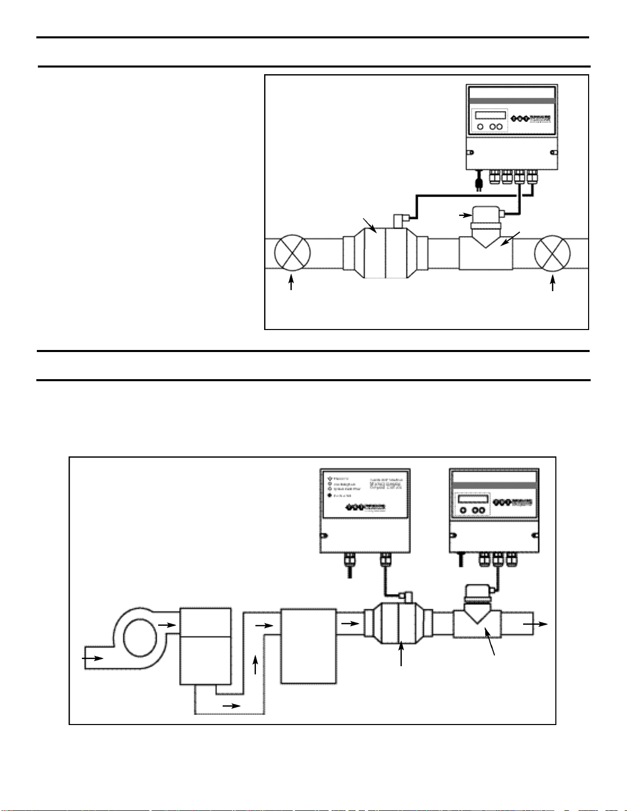
In general, installation of the IonGuard System should
follow these seven steps: Select a location on the
recirculating water line to insert the Ionization PVC
“T-Housing”. The location should be downstream of
the pump, filter, and Triangular Wave Deposit Control
System. [Recommended]
•Select a location on a wall to install the Power
Supply/Electronic Control Unit. The IonGuard
System installation kit includes 15 feet of wire in
a conduit/electrode wire assembly, which should
allow adequate flexibility when installing to Power
Supply.
• Install the two isolation valves (not included, in
those cases where equipment is below water
level) and the PVC “T-Housing”.
• Install the Power Supply/Electronic Control Unit.
•Install the Copper/Silver Ionization Electrodes
into the PVC “T-Housing”.
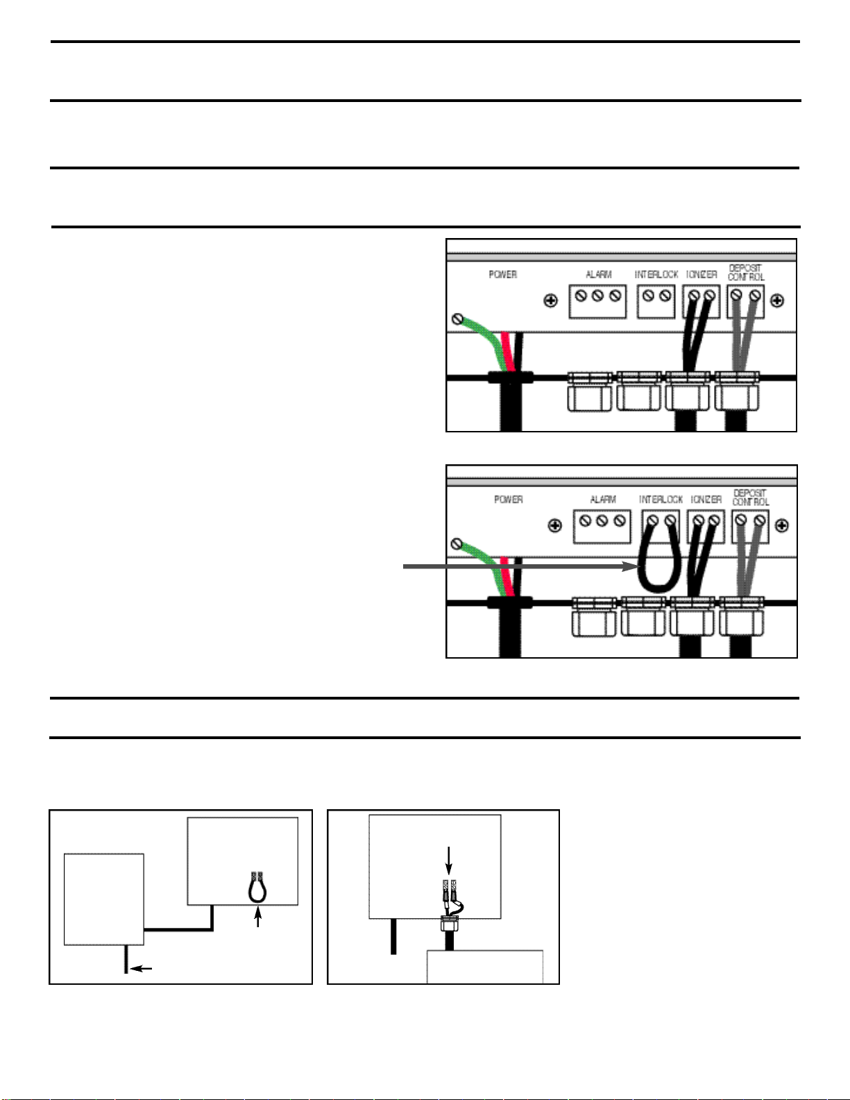
• Connect the conduit/electrode wire assembly
between the Power Supply and the Ionization
Electrodes.
• Connect the Ionization Power Supply to electrical
power.

Email:info@triangularwave.com • Triw[email protected] • Website:www.Triangularwave.com
3
Installation of the PVC “T-Housing”is site specific.
For best results, the Triangular Wave IonGuard
Purification System should be installed downstream
of the pump, the filter, and the Triangular Wave
Deposit Control System.
The connecting piping should include isolation valves
upstream and downstream of the PVC “T-Housing” to
facilitate replacement of the Copper/Silver
Electrodes.
SYSTEM INSTALLATION OVERVIEWSECTION 4
INSTALLATION
Continue section 3
Figure 1:IonGuard Purification System
Conduit / Electrode
Wire Assembly
AC Power Cord
Triangular Wave
Deposit Control System
( Recommended )
Power Supply
Electronic Control Unit
T-Housing
Electrodes
*Isolation Valve
*Isolation Valve
*Not included:See section 3 regarding installation
TWT Deposit Control
System
( Recommended )
TWT IonGuard
Purification System
TWT IonGuard T-Housing
TWT Deposit Control
Reaction Chamber
( Recommended )
Water Flow
PUMP
FILTER
HEATER
Pumps, piping, fittings, valves,and other material needed to and from system owners responsibility
The Ionization Purification System should
only operate when water is flowing through
the recirculating pipes; that is, when the
pump is operating. Two options are available
to insure the Ionization System and the
pump operate together.
•The AC power cord may be wired across
the pumps power supply; or
•The AC power cord may be plugged into
a 110/220 VAC outlet, and the “standby”
feature may be connected to
a flow switch or a timer switch.

Email:info@triangularwave.com • Triw[email protected] • Website:www.Triangularwave.com
4
CONNECTION OF THE IONGUARD SYSTEM TO ELECTRICAL POWER
SECTION 7
CONNECTION OF THE IONIZATION SYSTEM
TO THE CONNECTING PIPING
The PVC “T-Housing” should be fitted with appropri-
ate coupling fittings to allow it to be connected to the piping.All fittings should be tested for water tightness.
CONNECTION OF THE IONIZATION SYSTEM
TO REMOTE CONTROL SYSTEM
SECTION 5
SECTION 6
The IonGuard System maybe connected to a remote
control timer switch or flow switch. The connection
is made via a low voltage circuit. If the remote circuit
is closed, the Ionization System will be in normal
operating mode. If the remote control circuit is open,
the Ionization System will be in standby mode
(pump is off and the ionization system is not
energized).
If there ís no remote control circuit available, then
the jumper wire provided with the Ionization system
should be left in place on the two interlock standby
terminals. If the jumper wire is removed, the
Ionization system will go to standby mode.
LowVoltage Circuit Connections
Jumper cable on remote control contact terminals
The IonGuard Purification System should only operate
when water is flowing through the recirculating pipes;
that is, when the pump is operating. Two options are
available to insure the Ionization System and the
pump operate together.
Jumper Wire
in Place
Standby
Terminals
Remote Flow Switch
or Timer Switch
AC Electrical Cord AC Electrical Cord
Pump Power
Supply
The AC power cord may be wired across the pumpís
power supply;or The AC power cord may be plugged into a standard
110 VACoutlet, and the “standby” feature may be
connected to a flow witch or a timer switch.
The TWT®controller has a universal
power supply.The controller is shipped
with a North American 10A/125 VAC
Cordset.The user can cut off the con-
nector and install the desired connec-
tor or disconnect the cordset and
install the appropriate cordset.
Jumper
Wire

Email:info@triangularwave.com • Triw[email protected] • Website:www.Triangularwave.com
5
Read Copper Test Kit Instructions
Be sure to read, understand, and follow all of the
operating instructions for your copper and other test
kits. To minimize your overall operating costs while
maintaining proper disinfection levels, you will need
correct information from the test kits. See test kit
recommendation under Trouble Shooting Guide.
Adjust the Control Unit
Several steps must be followed to adjust the Control
Unit to achieve the proper copper level (0.25 to 0.35
parts per million). Start the system by pressing the
power button to ON (operation is indicated on the
diagnostic display window) and the selector to 50%
power level.The percentage will be displayed on the
alpha numeric display.
Using the copper test kit provided, test the copper
level twice per day in the morning and evening.
It should take no more than several days to achieve
the proper copper level (0.25 to 0.35 ppm). When
the proper level is reached, press the down button
to approximately 20% power level.
Copper ions do not dissolve or evaporate. They com-
bine with microorganisms in the water and kill the
microorganisms. It is important to operate the control
unit at the proper power level. With some
variation, operating the control unit between 10% and
30% power level should maintain the proper disinfec-
tion (copper) level of 0.25 to 0.35 ppm.The exact set-
ting will vary pump run time, size of system, and
other site specific conditions.
Once the proper copper level is reached, only weekly
testing of copper levels will be necessary.
Proper Copper Ion Level
Proper ion levels in your system should be 0.25 to
0.35 ppm.
If the copper level exceeds 0.5 ppm turn the unit off
until the copper level drops below 0.4 ppm.
• Algae Growth - 0.0 to 0.2 ppm
• Ideal Ion Level - 0.25 to 0.35 ppm
ADJUSTING THE IONGUARD SYSTEMSECTION 9
STEPS TO PUT THE IONGUARD SYSTEM IN SERVICE
SECTION 8
The following steps should be followed when placing
the IonGuard system in service:
1. Connect the system to the power source. (See Section 7)
2. Remote contacts for standby operation should
be closed or the local jumper wire should be
attached to the standby terminals.
3. Turn on power switch, the following should result:
• Display will show STANDBY for two seconds.
• Display will then show the current level set by
the Display Selector Control Button.( see figure A )
• Polarity indicator will show PLUS or MINUS.
Figure A
Diagnostic
Display
Window
Display
Selector
4. Disconnect the jumper wire or open the remote
control circuit. The following should result:
• Display will show

Email:info@triangularwave.com • Triw[email protected] • Website:www.Triangularwave.com
6
To use the Diagnostic Display window:
•Two pushes on Display Selector to view
diagnostic window
• The default window, will then display
“Electrodes Worn” when the controller has reach
the maximum voltage and can not provide the
“set” current.
I= Current in electrodes
V= Electrode Voltage
•When V= (between 23 or 24 volts), indicates
controllers maximum value.
• Maximum value will indicate electrodes worn and
spare electrodes should be made available.
•When the current in electrodes (I) is displayed and
when the value is below an acceptable level,
electrodes must be replaced.
REPLACING THE IONIZATION ELECTRODES
SECTION 10
Notes
Use the following steps to change the ionization
electrodes:
1. Shut off power to all systems
2. Shut off water
3. Remove protective cap from electrode were leads
4. Disconnect electrode wire leads
5. Unscrew electrode housing from reaction chamber
6. Remove depleted electrodes
7. Install new electrodes per the following procedure:
• Wrap electrode housing threads
with at least three wraps of
teflon tape
• Screw electrode housing into
PVC “ T-Housing”
8. Turn on power to all systems
9. Turn on water to test for leaks
10. Turn off power to all systems
11. Reconnect electrode wire leads
12. Replace protective cap
13. Turn power on
14. Check power supply display for proper indicator
IonGuard PVC “
T-Housing”

Email:info@triangularwave.com • Triw[email protected] • Website:www.Triangularwave.com
7
TROUBLE SHOOTING GUIDE
The TWT IonGuard controller has a diagnostic display,
this is accessed by two pushes of display selector.
The diagnostic display window has the following listings,
describing the content and their meaning:
• Each time the “selector” is operated the display will
“page” to the next display.This new page will remain
open for a short while so that the operator can adjust
the selection item if desired.The unit will close the page
if no action is taken.
•The system is digital.The adjustment are made with the
up and down push buttons.The selector push button is
used to display the correct page which allows this
adjustment.
The ionization control has an interlock that must be closed
for the ionization to be on.This provides for the control
(on/off) of this circuit.The circuit may be controlled by this
contact or the AC power may be switched on/off. The
controller will be shipped with a SHORT in place on these
terminals (see s iection 6).
When the ionization contacts are OPEN the display will be:
•The numbers will indicate the current the unit is provid
ing.This will be the same as the set when the
controller and the water conditions permit. If the unit can
not meet the set values it will display output current that
it is providing. (see section 9)
• Standby:This indicates that the ionization is
OFF and in a standby status.
When this circuit (interlock) is completed (shorted) the
display will be:
• Ionize 000%–Status OK
• Status OK indicates that the ionization is ON and in
service.
The ionization control is a current controller. The desired
current is set on the display.The output voltage will
increase to achieve the requested current.The controller
has been engineered with a maximum output voltage of 24
vdc. When this voltage can not provide the set current/
value, the unit will go into alarm.
To set the desired current you must select the set current
display (1 push of display selector).
• Push the up or down push button to change the set
current. The display will return to the standby screen in
a few seconds after the last push button activation.
•The units are amperes (amps) and volts.This display is
very useful in understanding the system status. Anytime
owner request assistance they should have these read-
ings available, to provide accurate information to person
assisting you .
As the electrodes wear or the water conditions change
(conductivity) the voltage required to set current will
increase.When this voltage reaches 24 vdc. it is at
maximum output.
•Electrodes Worn: The electrodes are approaching end of
life and should be replaced. Note, if the water
conductivity is low this alarm may appear when the elec-
trodes are still serviceable.This means that the water con-
ductivity will need to be increased for the system to oper-
ate (contact distributor for additional if required).
(see section 10)
• If the “electrodes worn” continues for five minutes the
system will then display:
•Ionize Error:
This indicates that the system “can not” provide the
requested current. At this point the operator should
review the diagnostic display and record the voltage and
current. If the unit is still indicating current, then one may
decide to delay changing the electrodes and if the water
conductivity improves, the system will reestablish the set
current. Even with an alarm error on the display the con-
troller will continue to provide the current that 24 vdc will
provide.
Audio Alarm:
• Alarm will intermittenly beep when the controller cannot
produce requested (set) current. If the alarm conditions
continues for 5 minutes, alarm will then change to
continous alarm.
•The audio alarm can be silenced by pushing the
up or down push button for three seconds.
SECTION 11

Email:info@triangularwave.com • Triw[email protected] • Website:www.Triangularwave.com
8
TROUBLE SHOOTING GUIDE
Your Triangular WaveTechnologies IonGuard
Purification System is manufactured in the USA
with premium electronic components. No period-
ic maintenance is required. The front panel dis-
play indicates the operational status of the sys-
tem. The indicators will not require replacement.
IF the indicators are not correct, check the AC
power and the wire to the electrodes.
The IonGuard System is designed to give you
many years of trouble free water system care;
however, if a problem does occur, the equipment
and chemical trouble shooting guides below
should help you correct the situation. If the prob-
lem persists, contact your TWT Distributor or
Triangular WaveTechnologies, Inc.
IF DO
Low Copper Reading Increase set current
Low Copper Reading with Clean or replace electrodes
Control Unit Full On
High Copper Level Decrease set current
Display is Inoperative Check power to system
Status Lights Inoperative Check power to system
“T-Housing” Water Leaks Tighten electrode assembly
ElectrodesWorn Check water flow (water must flow through
system) replace ionization elements
Alarm Signal Turn off power. Check electrode assembly
& connection cord for short or disconnect
Ionize Error Electrodes are nearing their useful life.
Order replacement electrodes.
Standby Signal See Section 7
CAUTION
Do not operate the IonGuard System without water in
the system and the pump operating. Disconnect power
before servicing. Drain system if unit is out of service
for extended period of time or in freezing temperatures.
We recommend that you keep this
operational manual near the system
being treated for reference.
Continue section 11

Email:info@triangularwave.com • Triw[email protected] • Website:www.Triangularwave.com
9
The controller is supplied with a wiring kit and a strain relief connector for
the solenoid coil wires. This strain relief will provide a water resistant seal
for the two coil wires. You should rotate the compression ring counter
clockwise to release pressure on the seal. Feed the two wires through the
provided holes and tighten the compression ring. Connect the two wires to
the coil terminals in the controller housing as illustrated.The systems are
provided with an alarm relay, which may be used for external alarms. The
relay contacts are rated 5 amps @ 120 vac.The contacts are isolated from
the control circuit and are single pole double throw.If an external alarm is
desired it may be connected to barrier terminals. (Refer to Figure B )
Introduction . . .
The Triangular Wave System is a technologically advanced method for the
treatment of hard water and its effect on fluid based applications.The system
is non-chemical by design and is suitable for all applications requiring hard
water treatment.
Operating Principals . . .
The signal from the Triangular Wave System circuitry flows to a solenoid coil
wound around the pipe treating and conditioning the fluid going through it.The
signal in the coil develops the modulated electrical field that immediately condi-
tions the water.The field penetrates the piping to its center, acting on the
passing water and the dissolved minerals and particles in the water.The
conditioning effects on the water are long lasting and last down stream.
TWTDCI-5C8-377 • TWTDCI-5C8-378 • TWTDCI-5C8-379 integrated deposit control and ionization treatment system
INSTRUCTIONS FOR THE USE OF TWT®DEPOSIT CONTROL TECHNOLOGY
TWT Deposit Controller / Solenoid Coil Terminal Hookup
Factory WrappedWire Coil Reaction Chambers Application
To use in conjunction with the TWT Deposit Control Systems, Triangular
WaveTechnologies, Inc. has developed a line of factory-wrapped wire
coil Reaction Chambers to address magnetic pipe environments.
Typically, wire coil cannot be installed on any magnetic pipe, such as
steel, galvanized steel, ductile iron, or cast iron. If a coil is applied to
such a pipe, the pipe becomes a shield and prevents the wave energy
from entering the fluid path. TWT Reaction Chambers solve this prob-
lem by providing an easily installed section of non-magnetic pipe to pro-
vide the proper pipe material for the Deposit Control System to work as
designed. TWT Reaction Chambers are fully sealed, protecting their layers
of factory-wrapped coil.
The TWT Reaction Chamber is part of the patented TWT Deposit
Control Technology. The Reaction Chamber provides a chamber
through which the water flows and is exposed to the triangular wave
signal that lies at the heart of the deposit control technology. As the
fluid passes through, it is treated and then carries that treatment downstream, to condition the rest of the plumbing
system, non-chemically and reliably.
When you have purchased a reaction chamber with cable and connecters with your controller unit, the correct
strain relief connecter for the controller is furnished with the cable for the reaction chamber. The strain relief
connecter on the controller (pipe solenoid) should be removed and replaced with the strain relief connecter
provided with the reaction chamber cable. The two wires should be connected to the coil terminals in the
controller housing as illustrated.
Strain Relief
Connecters
Reaction Chamber
Ground Electrical
Line Cord
Diagram B
Cables
Solenoid
Connecter
TWT Reaction
Chamber
Integrated
Controller
SECTION 12

Email:info@triangularwave.com • Triw[email protected] • Website:www.Triangularwave.com
10
The TWT deposit control systems have minimal
maintenance requirements and no moving parts.The
TWT deposit control systems should remain powered
on all of the time.The control panels have indicator
lights (see diagram ) and alarm circuits to show prob-
lems caused by external forces such as damage to
the coil, or insulation or damage to the electrical con-
nection.The alarm circuit may be connected to your
building control system, if desired.
The TWT deposit control systems are designed to
remain on continuously provided there are no exter-
nal interruptions, e.g., power outages), protecting
equipment from scale, bio-film and
corrosion. This is especially important for the equip-
ment that is idle. Of course, the system can and
should be disconnected from the power source when
being directly handled for installation, removal, sea-
sonal shutdown, or for other major equipment repair.
Recommended twice monthly Inspections:
The deposit controller, reaction chamber, and
fittings should be inspected visually for possible dam-
age. In addition, the control panel has the built-in
capacity for providing a 110-volt status signal in case
th system output is interrupted.
Distributed by
INSTRUCTIONS FOR THE USE OF TWT®DEPOSIT CONTROL TECHNOLOGY
Continue section 12
TWT Reaction
Chamber
Integrated
Controller
Indicator
Lights
Power On
Coil Energized
System Fault Error
Push to Test
Indicator Lights
On the TWT Deposit Control Integrated Treatment
System: If the deposit control reaction chamber is
not connected the red light will show solenoid
fault:
If TWT®deposit control system faults, contact
dealer or TWT, Inc.for technical assistance.

Email:info@triangularwave.com • Triw[email protected] • Website:www.Triangularwave.com
11
WARRANTY
All components of the Triangular Wave Microprocessor Deposit Control Systems are covered by a Five (5)
Year Warranty provided that:
1. No modifications are performed on the unit;
2. The system is installed as recommended by Triangular WaveTechnologies, Inc. and
3. There is no modification or change of installation without prior consultation with Triangular
WaveTechnologies, Inc. or its agents.
In the unlikely event that the unit becomes non-functioning, e.g., the “power” light and/or the “coil energized” light
are not receiving the signal & are not lit, please return the unit for replacement to the place of purchase, with proof
of purchase information.*
The Triangular Wave System does not affect the potability or the natural mineral content of the water, as there is no
direct contact with the water.Triangular Wave Technologies, Inc., therefore, accepts no responsibility for water quality..
Triangular WaveTechnologies, Inc. warrants that the Triangular Wave Microprocessor Deposit Control System will
perform as indicated in this Owner’s/ Installation Manual. If the product does not perform as indicated, the unit may
be returned within 90 days from the invoice date for a refund of the purchase price, less the direct cost of shipping,
installation.* Customer agrees that Triangular WaveTechnologies,Inc. or its agents will be given access to the
equipment for 90 days in order to monitor its performance, if desired, and/or to inspect the product and installation
prior to any requested return authorization.
Under no circumstances shall Triangular WaveTechnologies, Inc. or its agents be liable for consequential, special,
or contingent damages or other claims or demands in excess of the purchase price of its products.
The Deposit Control System is non-invasive and non-chemical by design, and is suitable for nearly all applications
requiring hard water treatment. The treatment process does not add anything to the fluid and should not cause
damage to piping or equipment. The Deposit Control System is designed to remove scale; if piping or equipment
has suffered corrosion prior to the installation of a TWT Deposit Control System, the removal of this scale may
potentially reveal cracks/pinholes in this piping or equipment that had been held together by this scale.
If structural damage or corrosion is suspected to exist, appropriate measures should be taken to alleviate this condition
prior to or in conjunction with the installation of the TWT Deposit Controller. Equipment owners must continue to be
responsible in standard infrastructure and equipment maintenance procedures as recommended by the manufacturers
of all piping and fluid fed equipment.
Triangular Wave Microprocessor Deposit Control System components should be inspected, upon receipt, for damage
that might occur during shipment.The carrier and Triangular WaveTechnologies, Inc. or its agents must be notified
immediately if damage is found.** With proper care during installation and maintenance, the system will provide
faithful service for many years.
*Triangular WaveTechnologies, Inc.or its Authorized Representatives must be notified prior to any return
for the proper Return Authorization, conditions and procedures.
**With the exception of TriangularWaveTechnologies, Inc.represented products / components, which are
covered by a separate standard warranty indicated in the products’Owners Installation Manual provided.
Triangular WaveTechnologies,Inc, provides total support before, during, and after the installation.
ProductWarranty
PerformanceWarranty ( 90 Days )
Although Triangular WaveTechnologies, Inc.has attempted to ensure the accuracy of the content of this publication,
and it’s website, it is possible that they may contain technical inaccuracies, typographical, or other errors. Triangular
WaveTechnologies,Inc.assumes no liability for any error in its publications, and for damages, whether direct, indirect,
incidental, consequential or otherwise.
Triangular WaveTechnologies, Inc.provides these publications “as they are”without warranty of any kind, either
express or implied, but not limited to implied warranties of merchantability or fitness for a particular purpose.
The published information in the publication and on the website are subject to change without notice. Triangular Wave
Technologies, Inc.reserves the right to make changes in the products, systems, design and layout without notification
to its customers.
This manual suits for next models
2
Table of contents
Other TWT Water Filtration System manuals