TYAN S5556 User manual

http://www.tyan.com
1
S5556
Version 1.0
Copyright
Copyright © 2019 MITAC COMPUTING TECHNOLOGY CORPORATION. All rights
reserved. No part of this manual may be reproduced or translated without prior
written consent from MITAC COMPUTING TECHNOLOGY CORPORATION.
Trademark
All registered and unregistered trademarks and company names contained in this
manual are property of their respective owners including, but not limited to the
following.
TYAN® is a trademark of MITAC COMPUTING TECHNOLOGY CORPORATION.
Intel® is a trademark of Intel® Corporation.
AMI, AMI BIOS are trademarks of AMI Technologies.
Microsoft®, Windows® are trademarks of Microsoft Corporation.
Nuvoton® is a trademark of Nuvoton Technology Corporation.
Notice
Information contained in this document is furnished by MITAC COMPUTING
TECHNOLOGY CORPORATION and has been reviewed for accuracy and reliability
prior to printing. MITAC assumes no liability whatsoever, and disclaims any express
or implied warranty, relating to sale and/or use of TYAN® products including liability
or warranties relating to fitness for a particular purpose or merchantability. MITAC
retains the right to make changes to product descriptions and/or specifications at
any time, without notice. In no event will MITAC be held liable for any direct or
indirect, incidental or consequential damage, loss of use, loss of data or other
malady resulting from errors or inaccuracies of information contained in this
document.

http://www.tyan.com
2

http://www.tyan.com
3
Contents
Before you begin… .................................................................................... 4
Chapter 1: Instruction ................................................................................ 5
1.1 Congratulations ................................................................................. 5
1.2 Hardware Specifications .................................................................... 5
1.3 Software Specifications ..................................................................... 8
Chapter 2: Board Installation ..................................................................... 9
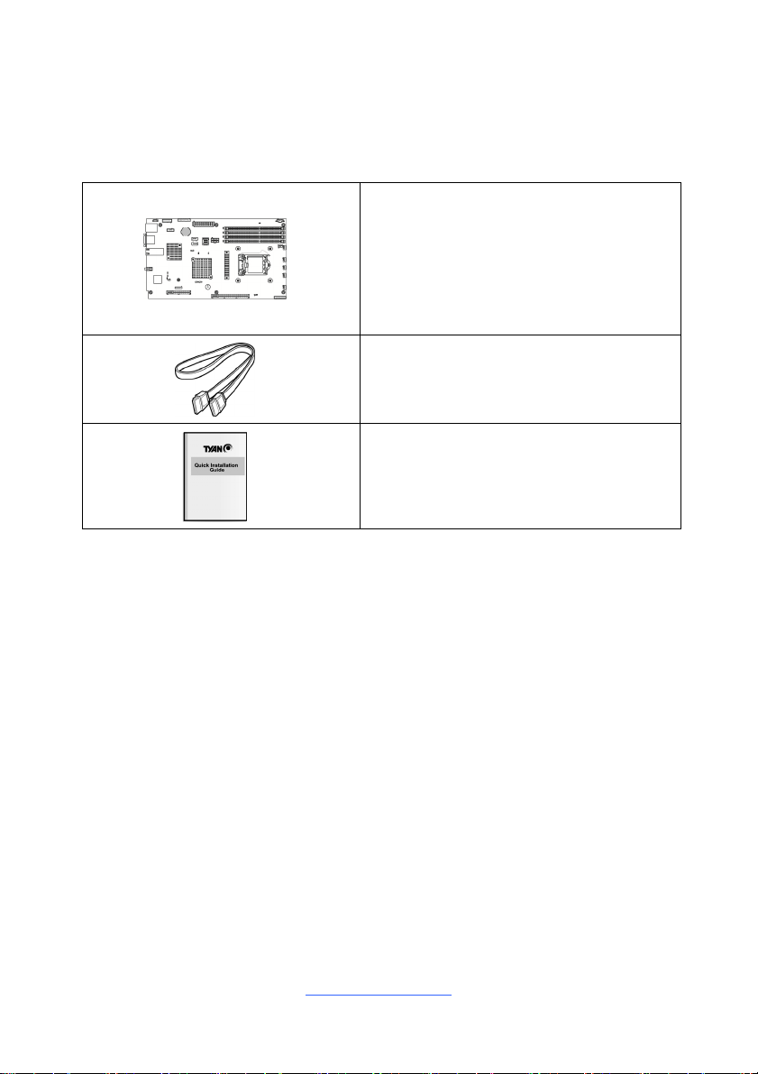
2.1 Board Image .................................................................................... 10
2.2 Block Diagram ................................................................................. 11
2.3 Mainboard Mechanical Drawing ...................................................... 12
2.4 Board Parts, Jumpers and Connectors ........................................... 13
2.5 Mainboard LED Definitions .............................................................. 22
2.6 Installing the Processor and Heat sink ............................................ 25
2.7 Thermal Interface Material .............................................................. 29
2.8 Tips on Installing Motherboard in Chassis ...................................... 30
2.9 Installing the Memory ...................................................................... 32
2.10 Attaching Drive Cables .................................................................. 35
2.11 Installing Add-In Cards .................................................................. 36
2.12 Connecting External Devices ........................................................ 37
2.13 Installing the Power Supply ........................................................... 39
2.14 Finishing Up ................................................................................... 40
Chapter 3: BIOS Setup ............................................................................. 41
3.1 About the BIOS ................................................................................ 41
3.2 Main Menu ....................................................................................... 43
3.3 Advanced Menu ............................................................................... 44
3.4 Chipset Menu .................................................................................. 84
3.5 Server Management ........................................................................ 95
3.6 Security .......................................................................................... 100
3.7 Boot ............................................................................................... 107
3.8 Save & Exit .................................................................................... 113
Chapter 4: Diagnostics ........................................................................... 115
4.1 Flash Utility .................................................................................... 115
4.2 AMIBIOS Post Code (Aptio) .......................................................... 116
Appendix: Fan and Temp Sensors........................................................ 123
Glossary ................................................................................................... 127
Technical Support .................................................................................. 133

http://www.tyan.com
4
Before you begin…
Check the box contents!
The retail motherboard package should contain the following:
1 x S5556 Motherboard
2 x SATA Cable
1 x S5556 Quick reference guide
IMPORTANT NOTE:
Sales sample may not come with the accessory listed above.
Please contact your sales representative to help order accessory for your
evaluation.

http://www.tyan.com
5
Chapter 1: Instruction
1.1 Congratulations
You have purchased the powerful TYAN® S5556 motherboard, based on the
Intel® C242 Series Chipset. The S5556 is designed to support single Intel®
Celeron G4900 Series and Intel Pentium Processor G5000 Series, Intel Xeon E-
2100 Series processor, 8th Gen. Intel Core i3 processor, and up to 64GB of
UDIMM ECC DDR4 2666/2400 memory. Leveraging advanced technology from
Intel®, the S5556 is capable of offering scalable 32 and 64-bit computing, high-
bandwidth memory design, and lightning-fast PCI-E bus implementation.
The S5556 not only empowers you in today’s demanding IT environment but also
offers a smooth path for future application upgradeability. All of these rich feature
sets provides the S5556 with the power and flexibility to meet demanding
requirements for today’s IT environments.
Remember to visit the TYAN® website at http://www.tyan.com. There you can
find all the information on all TYAN® products as well as all the supporting
documentation, FAQs, Drivers and BIOS upgrades.
1.2 Hardware Specifications
TYAN S5556 (S5556GM2NR-2T)
Processor
Q'ty / Socket Type (1) LGA1151
Supported CPU Series
Intel Celeron G4900 Series Processors and
Intel Pentium Processor G5000 Series, Intel
Xeon E-2100 series processors, 8th Gen. Intel
Core i3 processors
Thermal Design Power
(TDP) Wattage Max up to 95W
System Bus Up to 10.4/9.6 GT/s with Intel UltraPath
Interconnect (UPI) support
Chipset PCH Intel C242
Memory
Supported DIMM Qty (4) DIMM slots
DIMM Type / Speed UDIMM ECC DDR4 2666/2400
Capacity Up to 64GB
Memory channel 2 Channels per CPU
Memory voltage 1.2V
Expansion
Slots PCI-E (1) PCI-E Gen3 x16 slot (HH, HL) or (2) PCI-E
Gen3 x8 slots (HH, HL) * split by Mux.

http://www.tyan.com
6
(1) PCI-E Gen3 x8 slot (HH, HL)
Recommended TYAN Riser
Card M5556-L16-2F, PCI-E x16 1U riser card (left)
NOTE: The (1) PCI-E Gen3 x16 slot (HH, HL)
supports Tyan M5556-L16-2F riser card only.
LAN
Q'ty / Port (2) 10GbE ports,
(1) GbE port dedicated for IPMI
Controller Intel X550-AT2
PHY Realtek RTL8211E
Storage
SATA
Connector (2) SATA-DOM
Controller Intel C242
Speed 6.0 Gb/s
RAID RAID 0/1/10/5 (Intel RSTe)
sSATA
Connector (1) Mini-SAS HD (4-ports)
Controller Intel C242
Speed 6.0 Gb/s
RAID RAID 0/1/10/5 (Intel RSTe)
Graphic
Connector type D-Sub 15-pin
Resolution Up to 1920x1200
Chipset Aspeed AST2500
Input
/Output
Others (1) ID button
USB (2) USB3.1 Gen2 ports (at rear),
(2) USB3.1 Gen1 headers
COM (1) DB-9 COM Connector
VGA (1) D-Sub 15-pin VGA port (at rear)
RJ-45 (2) 10GbE ports,
(1) GbE port dedicated for IPMI
Front Panel (1) 2x12-pin SSI front panel header
SATA (2) SATA-III connectors +
(1) Mini-SAS HD (4-in-1) connector
Power ATX 24-pin + 8-pin power connectors
IPMB (1) 1x4-pin header
TPM
(Optional) TPM Support Please refer to our TPM supported list.
System
Monitoring
Chipset Aspeed AST2500
Fan Total (6) 4-pin headers
Temperature Monitors temperature for CPU & memory &
system environment

http://www.tyan.com
7
Voltage Monitors voltage for CPU, memory, chipset &
power supply
LED Over temperature warning indicator, Fan &
PSU fail LED indicator
Others Watchdog timer support
Server
Management
AST2500 iKVM Feature
24-bit high quality video compression,
Supports storage over IP and remote platform-
flash, USB 2.0 virtual hub
AST2500 IPMI Feature
IPMI 2.0 compliant baseboard management
controller (BMC), 10/100/1000 Mb/s MAC
interface
BIOS
Brand / ROM size AMI, 32MB
Feature
Hardware Monitor / PXE boot support / ACPI
sleeping states S5 / User Configurable FAN
PWM Duty Cycle / Console Redirection / ACPI
6.1 / SMBIOS 3.1 / PnP / Wake on LAN
Physical
Dimension
Form Factor Proprietary
Board Dimension 7.4" x 13" (188.3mm x 330mm)
Regulation
FCC (SDoC) Class A
CE (DoC) Class A
Operating
Environment
Operating Temp. 10° C ~ 35° C (50° F~ 95° F)
Non-operating Temp. - 40° C ~ 70° C (-40° F ~ 158° F)
In/Non-operating Humidity 90%, non-condensing at 35° C
RoHS RoHS 6/6 Compliant Yes
Operating
System OS supported list Please refer to our AVL support lists.
Package
Contains
Motherboard (1) S5556 Motherboard
Manual (1) Quick Installation Guide
Cable (SATA) (2) SATA signal cables
NOTE:
1. The specifications are subject to change without prior notice.
2. Please visit our Web site for the latest information.

http://www.tyan.com
8
1.3 Software Specifications
For OS (operation system) support, please check with TYAN® support for latest
information.

http://www.tyan.com
9
Chapter 2: Board Installation
You are now ready to install your motherboard.
How to install our products right… the first time
The first thing you should do is reading this user’s manual. It contains important
information that will make configuration and setup much easier. Here are some
precautions you should take when installing your motherboard:
(1) Ground yourself properly before removing your motherboard from the
antistatic bag. Unplug the power from your computer power supply and
then touch a safely grounded object to release static charge (i.e. power
supply case). For the safest conditions, MITAC recommends wearing a
static safety wrist strap.
(2) Hold the motherboard by its edges and do not touch the bottom of the
board, or flex the board in any way.
(3) Avoid touching the motherboard components, IC chips, connectors,
memory modules, and leads.
(4) Place the motherboard on a grounded antistatic surface or on the antistatic
bag that the board was shipped in.
(5) Inspect the board for damage.
The following pages include details on how to install your motherboard into your
chassis, as well as installing the processor, memory, disk drives and cables.
Caution!
1. To avoid damaging the motherboard and associated
components, use torque force within the range 5~7
kgf/cm (4.35 ~ 6.09 lb/in) on each mounting screw
for motherboard installation.
2. Do not apply power to the board if it has been
damaged.

http://www.tyan.com
10
2.1 Board Image
S5556
This picture is representative of the latest board revision available at the time of
publishing. The board you receive may not look exactly like the above picture.

http://www.tyan.com
11
2.2 Block Diagram
S5556 Block Diagram

http://www.tyan.com
12
2.3 Mainboard Mechanical Drawing

http://www.tyan.com
13
2.4 Board Parts, Jumpers and Connectors
This diagram is representative of the latest board revision available at the time of
publishing. The board you receive may not look exactly like the above diagram. But
for the DIMM number please refer to the above placement for memory installation.
For the latest board revision, please visit our web site at http://www.tyan.com.

http://www.tyan.com
14
Jumpers & Connectors
Connectors
1. RJ45 + 2 Port USB3.1 Gen2 (J62) 13. 4p FAN Connector (J36)
2. VGA (UPPER) + COM1 (LOWER)
(J56) 14. 5P_PSMI Header (J50)
3. RJ45*2 (J103) 15. 4PX2_ATX_PWR (PW2)
4. TPM (Trusted Platform Module)
Header (J102) 16. MINI SAS HD (J76)
5. PCI-Express Slot, x8 (J53) 17. 12Px2_ATX_PWR (PW1)
6. PCI-Express Slot, x16 (J55) 18. SATA/SATA DOM (J16)
7. 10Px2_FAN Board Header (J39) 19. 12Px2 SSI_FP Header (J32)
8. 4p FAN Connector (J37) 20. SATA/SATA DOM (J19)
9. 4p FAN Connector (J35) 21. 2 Port_USB3.1 GEN1 Header (J74)
10. 4p FAN Connector (J40) 22. 5Px2 SGPIO Header (J24)
11. 4p FAN Connector (J38) 23. 4P_IPMB Header (J31)
12. 4p FAN Connector (J34)
Jumpers
a ME FIRMWARE UPDATE (J10) e CPU PCI-E CONFIG (J43)
b CMOS CLEAR JUMPER (J12) F Power Button (J48)
c FLASH SECURITY OVERRIDE
(J106) g Reset Button (J49)
d PSU Alert Function (J105) h Chassis Intrusion (J33)
LEDs
i GRN / SYSTEM2 RST LED (LED12) vii RED / DIMM Error (LED8)
(LED5)
ii GRN / BMC_SW_HEARTBRAT
(LED2)
viii RED / CATERR (LED1)
(LED11)
iii GRN / BMC_HW_HEARTBRAT
(LED6) ix GRN / SYSTEM1 RST LED
iv RED / DIMM Error (LED3) x RED / PSMI_ALERT_LED
v RED / DIMM Error (LED4) xi ID LED (SW1)
vi RED / DIMM Error (LED7)

http://www.tyan.com
15
Jumper Legend
OPEN - Jumper OFF Without jumper cover
CLOSED - Jumper ON With jumper cover

http://www.tyan.com
16
J34/J35/J36/J37/J38/J40: 4-pin FAN Connector
Pin 1 2 3 4
Signal GND P12V TACH PWM
Use this header to connect the cooling fan to your motherboard to
keep the system stable and reliable.
J39: Fan Connector (Reserved for Barebone)
Signal Pin Pin Signal
TACH1 1 2 TACH6
TACH2 3 4 TACH7
TACH3 5 6 TACH8
TACH4 7 8 TACH9
TACH5 9 10 TACH10
GND 11 12 KEY
PWM2 13 14 PWM1
TACH11 15 16 SDA
TACH12 17 18 SCL
P3V3_AUX 19 20 PWM3
J32: Front Panel Header
Signal Pin Pin Signal
PW_LED+ 1 2 FP_PWR
KEY 3 4 ID_LED+
PWR_LED- 5 6 ID_LED-
HDD_LED+ 7 8 FAULT_LED1-

http://www.tyan.com
17
HDD_LED- 9 10 FAULT_LED2-
PWR_SW# 11 12 LAN1 ACTLED+
GND 13 14 LAN1 ACTLED-
RST_SW# 15 16 SMBus SDA
GND 17 18 SMBus SCL
SYS_ID_SW# 19 20 INTRUSION#
TEMP SENSOR 21 22 LAN2 ACTLED+
NMI_SW# 23 24 LAN2 ACTLED-
J36: PSMI Connector
Signal Pin Pin Signal
PSMI_CLK 1 2 PSMI_DAT
PSMI_ALERT 3 4 GND
VCC 5

http://www.tyan.com
18
J31: IPMB Pin Header
Signal Pin Pin Signal
IPMB-DAT 1 2 GND
IPMB-SCL 3 4 NC
J24: SATA SGPIO Pin Header
Signal Pin Pin Signal
SCL 1 2 SD1/SDO1
SDA 3 4 SDO0
GND 5 6 SLOAD
KEY 7 8 SCLOCK
V3AUX 9 10 HDD_FAULT
J16/J19: SATA/SATA DOM Connector
PIN Define Pin
Connects to the Serial
ATA ready drives via the
Serial ATA cable.
J16: SATA0/SATADOM1
J19: SATA1/SATADOM2
1 GND
2 Tx_DP
3 Tx_DN
4 GND
5 Rx_DN
6 Rx_DP
7 GND
P1 VCC (P5V)
P2 GND
J74: USB3.1 Gen1 Header
Signal Pin Pin Signal
VCC (P5V) 1 20 KEY
USB3.1_P1_RX_DN 2 19 VCC (P5V)
USB3.1_P1_RX_DP 3 18 USB3.1_P2_RX_DN
GND 4 17 USB3.1_P2_RX_DP
USB31_P1_TX_DN 5 16 GND
USB31_P1_TX_DP 6 15 USB31_P2_TX_DN
GND 7 14 USB31_P2_TX_DP

http://www.tyan.com
19
USB2.0_PA_DN 8 13 GND
USB2.0_PA_DP 9 12 USB2.0_PB_DN
OC_N ( NI ) 10 11 USB2.0_PB_DP

http://www.tyan.com
20
J102: TPM Header
Signal Pin Pin Signal
P3V3 1 2 LPC_FRAME_N
LPC_LAD0 3 4 KEY
LPC_LAD1 5 6 PLTRST_N
LPC_LAD2 7 8 GND
LPC_LAD3 9 10 CLK
IRQ_SERIAL 11 12 GND
FM_TPM_MOD_PRES_N 13 14 P3V3_AUX
P3V3(NI)/GND 15 16 RST_ESPI_RESET_N
PWR_BTN1: System Power Button
Signal Pin Pin Signal
FP_PWR_BTN_N 1 2 FP_PWR_BTN_N
GND 3 4 GND
RST_BTN1: System Reset Button
Signal Pin Pin Signal
FP_RST_BTN_N 1 2 FP_RST_BTN_N
GND 3 4 GND
J33: Chassis Intrusion Header
Signal Pin Pin Signal
PCH_INTRUDER_N 1 2 GND
J12: Clear CMOS Jumper
Normal (Default)
You can reset the CMOS settings by using this jumper. This can be
useful if you have forgotten your system/setup password, or need to
clear the system BIOS setting.
1. Power off system and disconnect power connectors from the
motherboard.
2. Remove the jumper from Pin_1 and Pin_2 (Default setting).
3. Move the jumper cap to close Pin_2 and Pin_3 for several seconds
to Clear CMOS.
4. Put jumper cap back to Pin_1 and Pin_2 (Default setting).
5. Reconnect power connectors to the motherboard and power on
system.
The system will power on for a few seconds, then shutdown and
reboot. This is a normal part of the CMOS clear process.
Clear CMOS
Table of contents
Other TYAN Motherboard manuals

TYAN
TYAN TYAN S1471 User manual

TYAN
TYAN M4985 User manual

TYAN
TYAN Tiger 100 S1832DL User manual

TYAN
TYAN S4992 User manual

TYAN
TYAN TIGER 200 User manual

TYAN
TYAN Tomcat i875P S5102 User manual

TYAN
TYAN Thunder n3600QX User manual

TYAN
TYAN S5548 User manual

TYAN
TYAN THUNDER K8SR User manual

TYAN
TYAN S8036 User manual

TYAN
TYAN Tempest i5100X User manual

TYAN
TYAN TOMCAT I810 User manual

TYAN
TYAN Tempest i5400XL User manual

TYAN
TYAN THUNDER GC-HE User manual

TYAN
TYAN TYAN S1572 ATX User manual

TYAN
TYAN Thunder i7500 Pro S2721 User manual

TYAN
TYAN TRINITY I845DDR User manual

TYAN
TYAN Tiger K8W S2875 User manual

TYAN
TYAN TRINITY KT User manual

TYAN
TYAN THUNDER K8HM User manual