NOTES
Proper operation of the Model
F302lF3021 Dry Pipe Value depends
upon its trim being installed in ac-
cordance with the instructions given
in this TechnicalData Sheet. Failure
to follow the trim diagram or the in-
structions given in this Technical
Data Sheet may prevent the
F302lF3021 Valve from functioning
properly, as well as void listings, ap-
provals, and the manufacturer’s war-
ranties.
The F302lF3021 Valves are shipped
with a restraining wire tied around
the Clapper Latch and Clapper Arm
to prevent movement of these compo-
nents during shipment.The restrain-
ing wire must be removed. Failure to
do so will prevent the F302lF3021
Valvefrom functioning properly.
The F302lF3021 Valve must be in-
stalled in a readily visible and acces-
sible location.
The F302lF3021 Valve and associ-
ated trim must be maintained at a
minimum temperature of 40°F/4”C.
Heat tracingofthe F302lF3021 Valve
or its associated trim is notpermitted.
Heat tracing can result in the forma-
tion of hardened mineral deposits
which are capable of preventing
proper operation.
The Model F302IF3021 Dry Pipe Valve
is to be installed in accordance with
the following criteria:
1. All nipples, fittings, and devices must
be clean and free of scale and burrs
before installation. Use pipe thread
sealant sparingly on male pipe
threads only
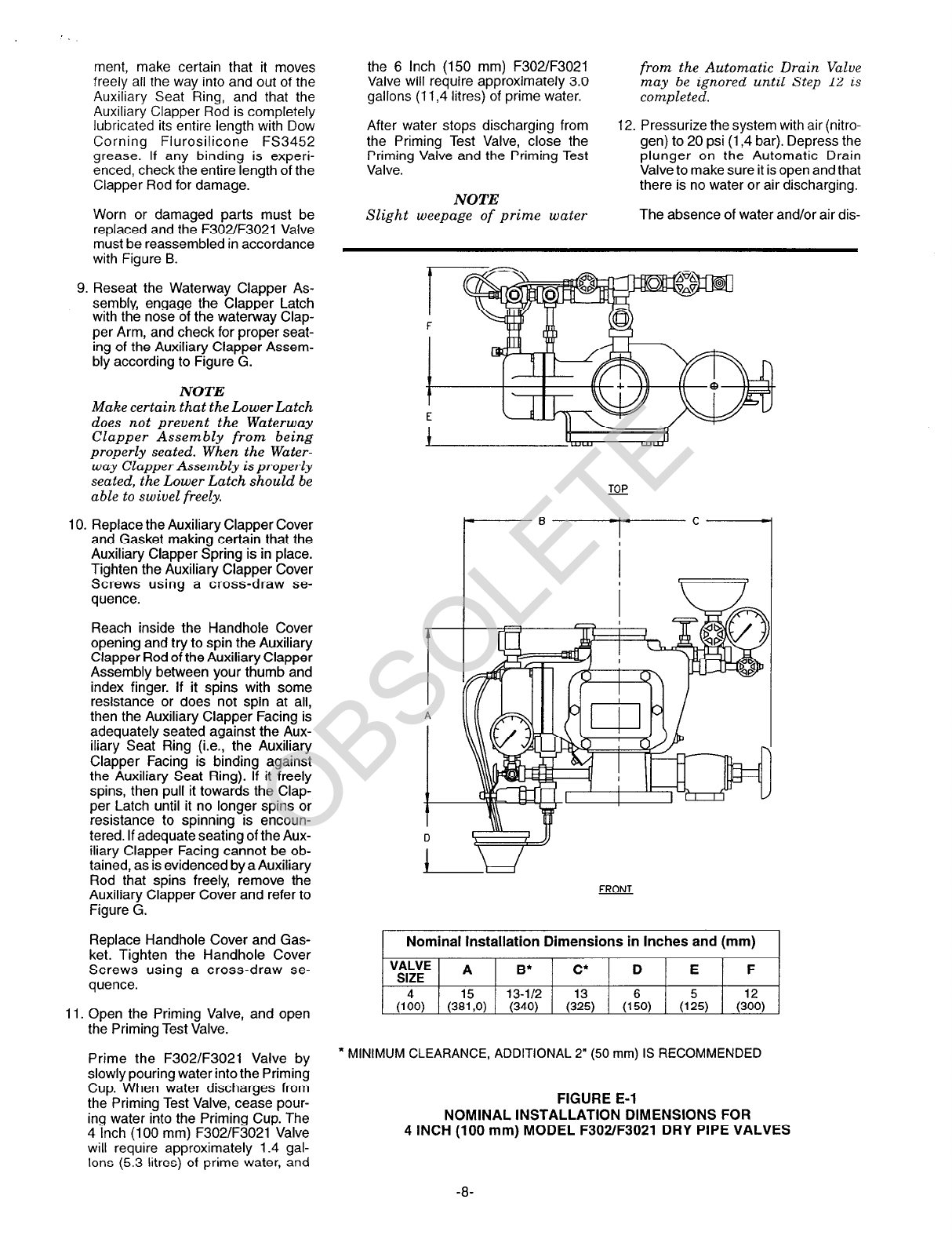
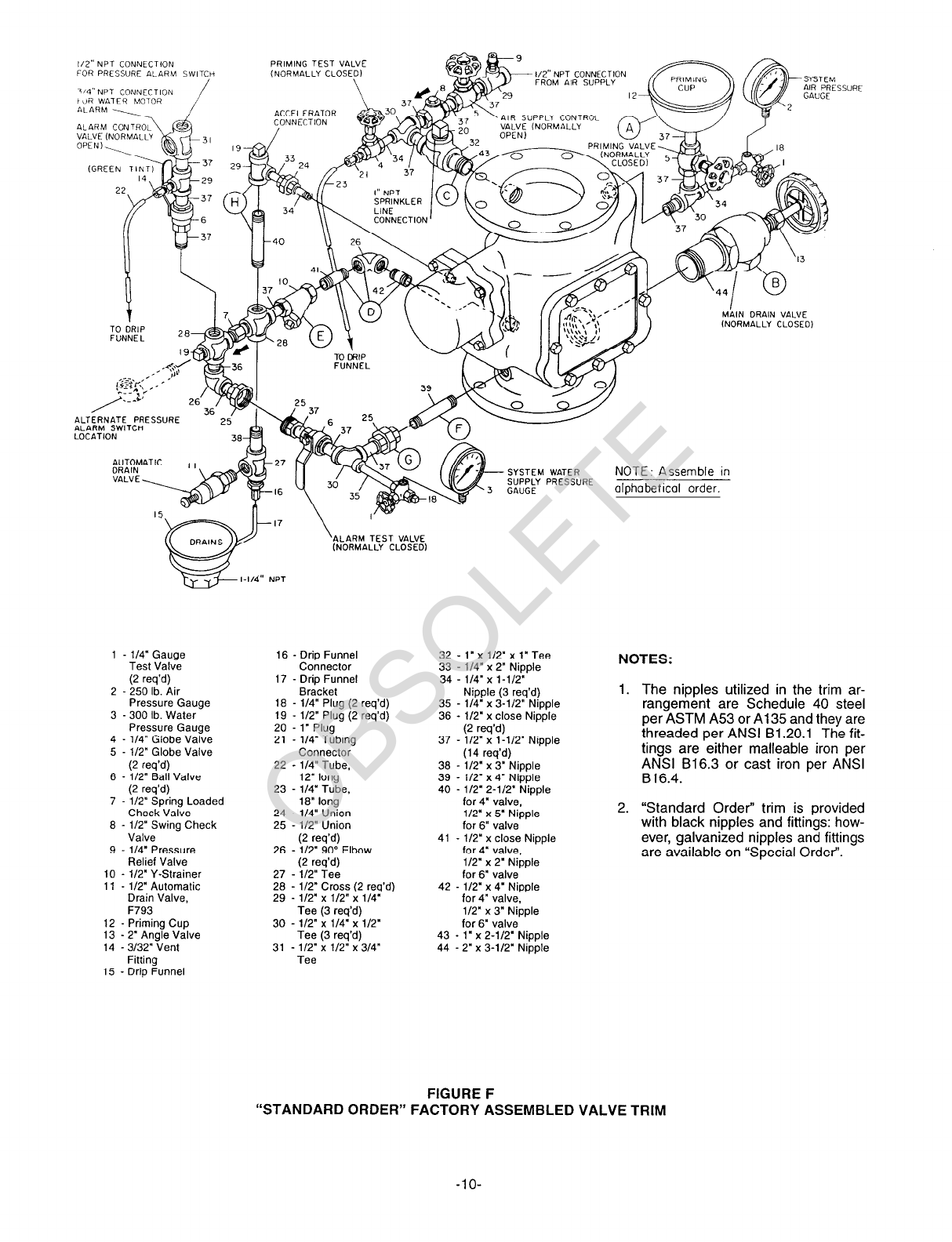
2. The F302/F3021 Valve must be
trimmed in accordance with Figure
E
3. Care must be taken to make sure
that check valves, strainers, globe
valves, etc. are installed with the flow
arrows in the proper direction.
4. Drain tubing to the drip funnel must
be installed with smooth bends that
will not restrict flow.
5. The main drain and drip funnel drain
may be interconnected provided a
check valve is located at least 12
inches (300 mm) below the drip fun-
nel.
6. Suitable provision must be made for
disposal of drain water. Drainage
water must be directed such that it
will not cause accidental damage to
property or danger to persons.
7. Unused pressure alarm switch
and/or water motor alarm connec-
tions must be plugged.
8. The Pressure Relief Valve provided
with the Valve Trim is factory set to
relieve at a pressure of approxi-
mately 45 psi (3,l bar), which can
typically be used for a maximum nor-
mal system air pressure of 40 psi
(2,8 bar). The Pressure Relief Valve
may be reset to a lower or higher
pressure; however, it must be be re-
set to relieve at a pressure which is
in accordance with the requirements
of the Authority Having Jurisdiction.
To reset the Pressure Relief Valve,
first loosen the jam nut and then
adjust the cap accordingly - clock-
wise for a higher pressure setting or
counterclockwise for a lower pres-
sure setting. After verifying the de-
sired pressure setting, tighten the
jam nut.
9. Installation of an Air Maintenance
Device, as described in the Techni-
cal Data Section, is recommended.
10. An Inspector’s Test Connection as
required By NFPA 13 must be pro-
vided on the system piping at the
most remote location from the
F302lF3021 Valve.
11. Conduit and electrical connections
are to be made in accordance with
the requirements of the authority
havina iurisdiction and/or the Na-
tional”El&tric Code.
12. Before hydrostatic tests are per-
formed in accordance with NFPA 13
system acceptance test require-
ments, the Waterway Clapper As-
sembly is to be manually latched
open (Ref. Figure C-2); the Automat-
ic Drain Valve (Item 1l-Fig. F) is to
be temporarily replaced with a l/2
inch NPT pipe plug; and, the Auxil-
iary Clapper Cover Screws, as well
as Handhole Cover Bolts, are to be
tightened using a cross-draw se-
quence.
Steps 1 through 17 are to be per-
formed when initially setting the Model
F302lF3021 Dry Pipe Valve; after an
operational test of the fire protection
system; or, after system operation due
to a fire.
1. Close the Main Control Valve, close
the Air Supply Control Valve, and
close the Accelerator Control Valve,
if applicable.
2. Open the Main Drain Valve and all
auxiliary drains in the system. Close
the auxiliary drain valves after water
3.
ceases to discharge. Leave the Main
Drain Valve open.
Depress the plunger of the Automat-
ic Drain Valve to verify that it is open
and that the F302/F3021 Valve is
completely drained.
4. Verify that both the Air and Water
Pressure Gauges are reading zero
(0).
5. Open the Alarm Control Valve (Fig.
F), if it was closed to silence local
alarms.
It is recommended that the Alarm
Control Valve be wire sealed in the
open position with a No. 16 twisted
wire, the ends of which are secured
by a lead seal. The wire seal should
be looped through the hole in the
handle and tightly twisted around the
pipe nipple adjacent to the handle.
6. Disassemble the Y-Strainer (Item 10,
Fig. F), thoroughly clean-out the
basket, and then reassemble the Y-
Strainer.
7. As necessary, replace all sprinklers
that have operated. Replacement
sprinklers must be of the same type
and temperature rating as those
which have operated.
NOTE
In order to prevent the possibility
of a subsequent operation of an
overheated solder type sprinklel;
any solder type sprinklers which
were possibly exposed to a tem-
perature greater than their maxi-
mum rated ambient must be re-
placed.
8. Remove the Handhole Cover, and
then remove the Auxiliary Clapper
Cover, being careful not to lose the
Auxiliary Clapper Spring.
Thoroughly clean all interior parts of
the F302/F3021 Valve, and make
certain that the Communicating Port
(Ref. Fig. C-l ) between the Body and
the Auxiliary Clapper Cover is wide
open.
Use a clean cloth to to wipe the
Auxiliary and Waterway Clapper
Seat Rings, as well as the Clapper
Facings. Inspect the Clapper Fac-
ings and Seat Rings for damage.
After unlatching the Waterway Clap-
per Assembly from its tripped
(latched) position (Ref. Figure C-2),
check the Waterway Clapper As-
sembly, Auxiliary Clapper Assembly,
Clapper Latch, Upper Latch and
Lower Latch for freedom of move-
ment.
When checking the Auxiliary Clap-
per Assembly for freedom of move-
-7-