Tyco Fire Product STAR SPRINKLER S370 User manual

Automatic Residential Domestic
Shut-Off Valve, 2 Inch (50 mm)
Model S370
GENERAL DESCRIPTION
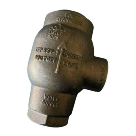
The Star 2 inch (50 mm) Model S370 Automatic Residen-
tial Domestic Shutoff Valve is intended for use in dual-pur-
pose residential water supply piping that serves both do-
mestic and NFPA 13D or 13R residential fire protection
sprinkler system needs.When an automatic fire sprinkler
operates, the S370 Valve will automatically shut off water
flow to the domestic system and divert the available water
supply to the fire sprinkler system. Consequently, when
the S370 is utilized, the system designer need not add
the domestic flow demand to the fire sprinkler system
flow demand, as would otherwise be required by NFPA
13D or 13R.
Use of the Model S370 Automatic Residential Domestic
Shutoff Valve should be considered when either the water
supply cannot adequately provide for both the domestic
design demand and fire sprinkler flow demand, or it is de-
sirable to increase the effectiveness of the fire sprinkler
system by automatically shutting off domestic flow.
The S370 maximizes the effective use of a limited water
supply. It may eliminate the need to add costly pumps,
pressurized reservoirs, or electrically operated domestic
shutoff valves. The S370 has a built-in check valve in the
fire sprinkler system outlet that eliminates the need for a
separate check valve. Also, the S370 automatically resets,
thereby eliminating the need for valve disassembly after a
fire sprinkler system test or operation.
WARNING
The Model S370 Automatic Residential Domestic Shut-
Off Valve described herein must be installed and main-
tained in compliance with this document, as well as with
the applicable standards of the National Fire Protection
Association, in addition to the standards of any other
authorities having jurisdiction. Failure to do so may impair
the integrity of this device.
The owner is responsible for maintaining his fire protec-
tion system and devices in proper operating condition.
The installing contractor or sprinkler manufacturer should
be contacted relative to any questions.
TECHNICAL DATA
Approvals
UL and C-UL Listed.
Maximum Working Pressure
175 psi (12.1 bar).
End Connections
2inchNPT
Friction Loss
RefertoFigure4.
Physical Characteristics
The body, cover, and piston are bronze, and the piston is
Teflon†coated.The fire sprinkler line seals and domestic
line seal are silicone rubber, the spring is stainless steel,
and the cover O-ring is Buna-N.
OPERATION
The design of the S370 Valve is such that if there is a fire
sprinkler operation during domestic usage, the S370
Valve will automatically shut off flow to the domestic sys-
tem and divert the available water supply to the fire sprin-
kler system. This eliminates the lower flow into the sprin-
kler system that might otherwise be caused by possible
significant domestic water usage.
When the S370 Valve is in the normal standby position as
shown in Figure 3, the Piston, assisted by the Spring, is
in the down position. With the Piston in the down position,
the Fire Sprinkler Seals permit the S370 to perform as a
conventional check valve. Also, with the Piston in the
down position, water is available on demand through the
Domestic Flow Passage and out the Domestic Port.
Upon operation and a minimum 5 GPM (19 LPM) water
flow to the automatic residential fire sprinkler system, the
Piston moves upward.With the Piston in the up position,
414-570-5000 • 800-558-5236 • FAX 414-570-5010 6-99
2-7.1.10
STAR SPRINKLER INC.
E-mail starsprk@execpc.com
#4200
†DuPont Registered Trademark
OBSOLETE

any water flow to the Domestic Flow Port is diverted to
the Fire Sprinkler Flow Port.
The contours of the Piston have been specifically config-
ured to minimize its upward movement except under the
level of sustained fire sprinkler system flow resulting from
operation of one or more fire sprinklers. However, be-
cause most fire sprinkler systems contain air pockets, the
Piston will tend to move momentarily upward if there is a
surge in supply pressure. The momentary opening and re-
closing of the Piston at the Fire Sprinkler Line Seals will
trap a portion of the pressure increase within the fire
sprinkler system. The trapping of pressure increases
within the fire sprinkler system will help to reduce the pos-
sibility of a subsequent surge in the supply pressure from
causing the waterflow detector to signal a false alarm.
As indicated above, domestic system usage may reduce
the pressure available to the fire sprinkler system.How-
ever, when utilizing the S370 Valve, it is not necessary to
take into account the complex hydraulic modeling of the
domestic system that would otherwise be required to de-
termine the minimum possible residual (flowing) pressure
that would be available to the fire sprinkler system.
For operation of the S370 Valve, it is only necessary to de-
sign the fire sprinkler system, from the water supply main
to the most hydraulically remote sprinkler, to provide a
minimum single sprinkler flow of 5 GPM (19 LPM), when
the supply pressure at the main is at its minimum ex-
pected value. Actual sprinkler demand for the most hy-
draulically remote fire sprinkler should be in accordance
with the manufacturer’s minimum acceptable flow and
pressure, but the minimum flow must be at least 5 GPM
(19 LPM).
DESIGN CRITERIA
In order for the S370 Valve to automatically operate once
a fire sprinkler operates, the fire sprinkler system from
the water supply main to the most hydraulically remote
sprinkler must be designed to provide a minimum single
sprinkler flow of 5 GPM (19 LPM), when the water supply
pressure at the water supply main is at its minimum ex-
pected value.
NOTES
The minimum single sprinkler flow rate of 5 GPM (19
LPM), required for use with the S370 Valve, does not
take precedence over any more hydraulically demanding
single or multiple sprinkler flow rates specified for the resi-
dential sprinklers being utilized.
INSTALLATION
The Model S370 Automatic Residential Domestic Shut-
Off Valve must be installed in accordance with the follow-
ing instructions:
NOTE
A fire sprinkler water supply connection to a public water
supply is usually subject to local regulations concerning
metering and backflow prevention requirements. Consult
with the local water authorities concerning local require-
STAR SPRINKLER INC.
Page 2 2-7.1.10
FIGURE 1
MODEL S370 AUTOMATIC RESIDENTIAL
DOMESTIC SHUT-OFF VALVE
4-5/8"
(117.5 mm)
4-9/16"
(115.9 mm)
5-3
/
8" DIA.
(136.5 mm)
3-3/4"
(95.3 mm)
9-3/16"
(233.4 mm) 5
2
3
7
4
1
FIRE
PORT,
2" NPT
SUPPLY
PORT,
2" NPT
DOMESTIC
6
PORT,
2" NPT
SPRINKLER
WATER
NO. DESCRIPTION .....QTY.
1 Body...........1
2 Cover ..........1
3 Piston ..........1
4 Spring..........1
5 Fire Sprinkler Line Seal . 2
6 Domestic Line Seal . . . 1
7 CoverO-Ring......1
FIGURE 2
TYPICAL INSTALLATION
OBSOLETE

ments which may apply to the arrangement of these com-
ponents in the fire sprinkler system water supply.
Figure 2 illustrates a typical arrangement using the
Model S370 Automatic Residential Domestic Shutoff
Valve. The arrangement may need to be modified to meet
the requirements of the authority having jurisdiction;how-
ever, the Model S370 Automatic Residential Domestic
Shutoff Valve must be installed in accordance with the fol-
lowing criteria:
1. The S370 Valve is to be installed vertically with the Sup-
ply Port at the bottom, the Fire Sprinkler Port at the top,
and the Domestic Port at the side. It is recommended
that a suitable clamp be installed along the water supply
riser piping to provide support for the weight of the S370
Valve.
2. The water supply to the S370 Valve must be free of con-
taminants and particles of a size greater than 1/8 inch
(3.2 mm).
3. The S370 is to be installed so that the arrows cast on
theBodypointinthedirectionofflow.
4. A Domestic Control Valve is to be located between the
S370 Valve and the domestic system. The inlet to the
Domestic Control Valve is to be located within 12 inches
(300 mm) of the Domestic Port of the S370 Valve.
5. The Drain and Flow Test Connection (Ref. Figure A)
must be minimum 1/2 inch for systems per NFPA 13D
or minimum 1 inch size for systems per NFPA 13R.
6. An Inspector’s Test Connection with a test orifice equal
to the smallest K-factor sprinkler in the system is to be
located at the most hydraulically demanding location in
the system (usually adjacent to the highest and most re-
mote sprinkler).
7. Apply pipe thread sealant sparingly only to the 2 inch NPT
male pipe threads which are to be assembled to the three
ports of the S370 Valve. The use of a Teflon
†
based pipe
thread sealant is recommended.
STAR SPRINKLER INC.
2-7.1.10 Page 3
FIGURE 3
STANDBY AND OPERATED POSITIONS OF THE
2 INCH (50 mm) MODEL S370 AUTOMATIC RESIDENTIAL DOMESTIC SHUT-OFF VALVE
SPRINKLER
SEALS
SEAL
WATERFLOW TO
FIRE SPRINKLERS
WATERFLOW
SYSTEM
WATERFLOW
FROM SUPPLY
WATERFLOW
FROM SUPPLY
STANDBY OPERATED
FIRE
DOMESTIC
TO DOMESTIC
PASSAGE
FLOW
DOMESTIC
(CLOSED)
(ENGAGED)
PISTON STOP
MECHANICAL FIRE
SPRINKLE
R
PASSAGE
FLOW
(OPEN)
SPRINKLER
PASSAGE
(CLOSED)
FLOW
FIRE
(OPEN)
DOMESTIC
PASSAGE
FLOW
SPRING
PISTON
OBSOLETE

SETTING PROCEDURE
Steps 1 through 10 are to be performed when initially fill-
ing the fire sprinkler and domestic system piping with
water or after a fire sprinkler operation (Ref. Figure 2).
1. Close the Main Control Valve.
2. Close the Domestic Control Valve, and all water outlets
in the domestic piping system.
3. Close all drain valves in addition to the Drain and Flow
Test Connection in the fire sprinkler system, and replace
all operated sprinklers as necessary.
4. Partially open the Main Control Valve until the sound of
flowing water just begins, and then leave the Main Con-
trol Valve in the partially open position.
5. After the fire sprinkler system pressure gauge indicates
approximately the same pressure as the supply pres-
sure gauge, fully open the Main Control Valve.
6. Open the Inspector’s Test Connection. After trapped air
has been relieved, close the Inspector’s Test Connec-
tion.
7. Open the highest elevation outlet on the domestic sys-
tem.
8. Partially open the Domestic Control Valve until the
sound of flowing water begins. Allow the domestic pip-
ing to slowly fill with water.
9. Close the highest elevation water outlet on the domestic
system when unaerated water begins to flow.
10. Completely open the Domestic Control Valve, and then
check that the domestic system is properly pressurized
by verifying that at least three water outlets in the do-
mestic system can flow full at the same time.
If the water outlets flow full, the S370 Valve is set and
ready for service and the water outlets on the domestic
system may be closed.
If the water outlets do not flow full, reclose the Domestic
Control Valve, wait a minimum of ten seconds, and en-
sure that there is no flow from the fire sprinkler system
piping. Reopen the Domestic Control Valve and then re-
check that the water outlets are flowing full.
MAINTENANCE AND SERVICE
The Model S370 Automatic Residential Domestic Shutoff
Valve does not require any regularly scheduled mainte-
nance. However, proper operation of the S370 Valve
should be verified at least annually (preferably quarterly)
during system alarm inspections. Any impairment must
be immediately corrected.
It is also recommended that fire protection systems be in-
spected by a qualified Inspection Service.
NOTES
No attempt is to be made to repair any S370 Valve com-
ponent in the field.
The operational test and flow test procedures will result in
operation of the associated alarms, as well as an interrup-
tion of the domestic water supply service. Consequently,
notification must be given to the owner and the fire depart-
STAR SPRINKLER INC.
Page 4 2-7.1.10
FIGURE 4
NOMINAL PRESSURE LOSS VERSUS FLOW
FLOW RATE IN GALLONS PER MINUTE (GPM)
FIRE SPRINKLER PORT
DOMESTIC PORT
105 20 30 40 70 100 150
IN POUNDS PER SQUARE INCH (PSI)
NOMINAL PRESSURE DROP
1.0
2.0
3.0
OBSOLETE

ment, central station, or other signal station to which the
alarms are connected, and notification must be given to
the building occupants.
Before closing a fire protection system main control valve
for maintenance work on the fire protection system that it
controls, advise all occupants of the residence that the
fire protection system is being disabled.
Operation Test Procedure
1. Fully open any three water outlets in the domestic piping
system.
2. Open the Inspector’s Test Connection of the fire sprin-
kler system to simulate a sprinkler operation.
3. Verify that the alarms are operating and that the flow
from the domestic water outlets has decreased to a
trickle.
4. Close the Inspector’s Test Connection to allow the S370
Valve to automatically reset. Automatic resetting occurs
within ten seconds, after which the previously opened
three domestic system water outlets will once again flow
full. In which case, the S370 Valve is set and ready for
service and the water outlets on the domestic system
maybeclosed.
If the water outlets do not flow full, close the Domestic
Control Valve, wait a minimum of ten seconds, and en-
sure that there is no flow from the fire sprinkler system
piping. Reopen the Domestic Control Valve and then re-
check that the domestic system water outlets are flow-
ing full.
Flow Test Procedure
1. Completely open the Drain and Flow Test Connection.
2. While water is flowing, record the pressure reading on
the fire sprinkler system pressure gauge and then com-
pare this reading to previous readings. If there is a sig-
nificant decrease in pressure since the last time the
pressure reading was taken which is not due to a nor-
mally expected drop in the water supply pressure, there
may be an impairment that should be immediately identi-
fied and corrected.
3. Close the Drain and Flow Test Connection to allow the
S370 Valve to automatically reset. Automatic resetting
will occur within ten seconds.
4. After waiting ten seconds, completely open at least
three water outlets in the domestic system and allow
them to simultaneously flow.
If the water outlets flow full, the S370 Valve is set and
ready for service and the water outlets on the domestic
system may be closed.
If the water outlets do not flow full, close the Domestic
Control Valve and verify that there is no flow from the
fire sprinkler system piping (such as at the Inspector’s
Test Connection). Wait a minimum of ten seconds. Re-
open the Domestic Control Valve and then recheck that
the domestic system water outlets are flowing full.
NOTE
After returning a fire protection system to service, notify
the proper authorities and advise those responsible for
monitoring proprietary and/or central station alarms.
ORDERING PROCEDURE
Please Specify:
2 Inch Model S370 Automatic Residential Domestic
Shut-Off Valve (#4200).
AVAILABILITY AND SERVICE
Star Sprinkler Inc. products and devices are available
worldwide through a network of independent distributors.
Please contact Star Sprinkler Inc. for information and the
name and address of the Star distributor in your area.
LIMITED WARRANTY
The manufacturer warrants for a period of one year from
the date of sale (warranty period) that the product(s) sold
hereunder are free from defects in material and workman-
ship. Our obligation under this warranty is limited to repair
or replacement, or, at our option, we will repay the price
paid for the product(s), plus any transportation charge
paid by the purchaser.In the case of replacement, we will
pay the transportation charges to the location of the de-
fective product.We must be given the opportunity to in-
spect any product you believe to be defective. To make a
claim under this limited warranty, you should contact our
Sales Services Manager at (800) 558-5236.
THERE ARE NO OTHER WRITTEN OR ORAL WARRAN-
TIES. ALL IMPLIED WARRANTIES OF MERCHANT-
ABILITY AND FITNESS FOR A PARTICULAR PUR-
POSE ARE LIMITED IN DURATION TO THE DURATION
OF THE LIMITED WARRANTY SET FORTH ABOVE.
The manufacturer does not assume any other obligation
in connection with the sale of the product(s) by purchaser.
This warranty shall not apply to any product(s) which
have been installed in violation of written instructions fur-
nished by the manufacturer, repaired or altered, misused
or damaged, or not properly maintained.
The manufacturer is not liable for indirect, incidental or
consequential damages in connection with the use of the
product(s).
Some states do not allow limitations on how long an im-
plied warranty lasts, or exclusion or limitation of incidental
or consequential damages, so the above limitations or ex-
clusion may not apply to you.
THIS WARRANTY GIVES YOU SPECIFIC LEGAL
RIGHTS, AND YOU MAY ALSO HAVE OTHER RIGHTS
WHICH VARY FROM STATE TO STATE.
STAR SPRINKLER INC.
2-7.1.10 Page 5
OBSOLETE

STAR SPRINKLER INC.
Page 6 2-7.1.10
7071 S. 13th Street • Suite 103
Oak Creek, WI 53154
414-570-5000 • 800-558-5236 PRINTEDINU.S.A.6-99
OBSOLETE
Table of contents
Other Tyco Fire Product Control Unit manuals
Popular Control Unit manuals by other brands

oventrop
oventrop Aquastrom DT Installation and operating instructions for the specialised installer

Interlogix
Interlogix NXG-7002 Installation sheet

Aruba
Aruba S3500 Series Uplink Module installation guide

Pickering
Pickering PXI BRIC 40-563A user manual

Spirax Sarco
Spirax Sarco UFT32 manual

Woodward
Woodward 721 Operation and calibration manual