Type EA-1 PROTECTOSPRAY
Directional Spray Nozzles, Automatic,
Medium Velocity
Worldwide
Contacts
www.tyco-fire.com
Page 1 of 6 MARCH 2014 TFP800
IMPORTANT
Always refer to Technical Data
Sheet TFP700 for the “INSTALLER
WARNING” that provides cautions
with respect to handling and instal-
lation of sprinkler systems and com-
ponents. Improper handling and in-
stallation can permanently damage
a sprinkler system or its compo-
nents and cause the sprinkler to fail
to operate in a fire situation or cause
it to operate prematurely.
General
Description
The TYCO Type EA-1 PROTECTO-
SPRAY Directional Spray Nozzles are
automatic (frangible bulb) directional
spray nozzles designed for use in water
spray xed systems for re protection
applications. They are external deec-
tor-type nozzles that discharge a uni-
formly lled cone of medium velocity
water droplets.
The Type EA-1 PROTECTOSPRAY Di-
rectional Spray Nozzles are effective in
covering exposed vertical, horizontal,
curved, and irregular shaped surfaces
in a cooling spray to prevent excessive
absorption of heat from an external
re and possible structural damage or
spread of re to the protected equip-
ment. However, use of an automatic
nozzle requires consideration of the re-
sponse time of the thermal element.
The Type EA-1 PROTECTOSPRAY Di-
rectional Spray Nozzles are also espe-
cially effective for area coverage and
are sometimes used in lieu of standard
sprinklers where directional spray is
considered more appropriate. In some
applications, depending on water de-
sign density requirements, the Type
EA-1 Nozzles are also used for re con-
trol or extinguishment.
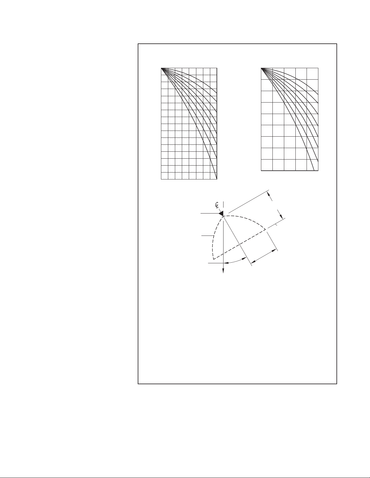
The Type EA-1 PROTECTOSPRAY Di-
rectional Spray Nozzles are available
in three orice sizes and a wide variety
of spray angles (included angle of dis-
charge), as well as temperature ratings
to provide versatility in system design.
It is recommended that the end user be
consulted with respect to the suitabil-
ity of the materials of construction and
nish for any given corrosive environ-
ment. The effects of ambient tempera-
ture, concentration of chemicals, and
gas/chemical velocity should be con-
sidered, at a minimum, along with the
corrosive nature to which the sprinklers
may be exposed.
The Type EA-1 PROTECTOSPRAY Di-
rectional Spray Nozzle is a re-designa-
tion for the Gem Type EA-1.
NOTICE
The Type EA-1 PROTECTOSPRAY Di-
rectional Spray Nozzles described
herein must be installed and maintained
in compliance with this document, as
well as with the applicable standards
of the National Fire Protection Associa-
tion, in addition to the standards of any
authorities having jurisdiction. Failure
to do so may impair the performance of
these devices.
The design of individual water spray
fixed systems can vary considerably,
depending on the characteristics and
nature of the hazard, the basic purpose
of the spraying system, the configura-
tion of the hazard, and wind/draft con-
ditions. Because of these variations, as
well as the wide range of available noz-
zle spray characteristics, the design of
water spray fixed systems for fire pro-
tection must only be performed by ex-
perienced designers who thoroughly
understand the limitations as well as
capabilities of such systems.
The owner is responsible for maintain-
ing their fire protection system and de-
vices in proper operating condition. The
installing contractor or sprinkler manu-
facturer should be contacted with any
questions.
Technical
Data
Approvals
UL and C-UL Listed
FM Approved
Maximum Working Pressure
175 psi (12,1 bar)
(Also refer to Figure 2, Note 2)
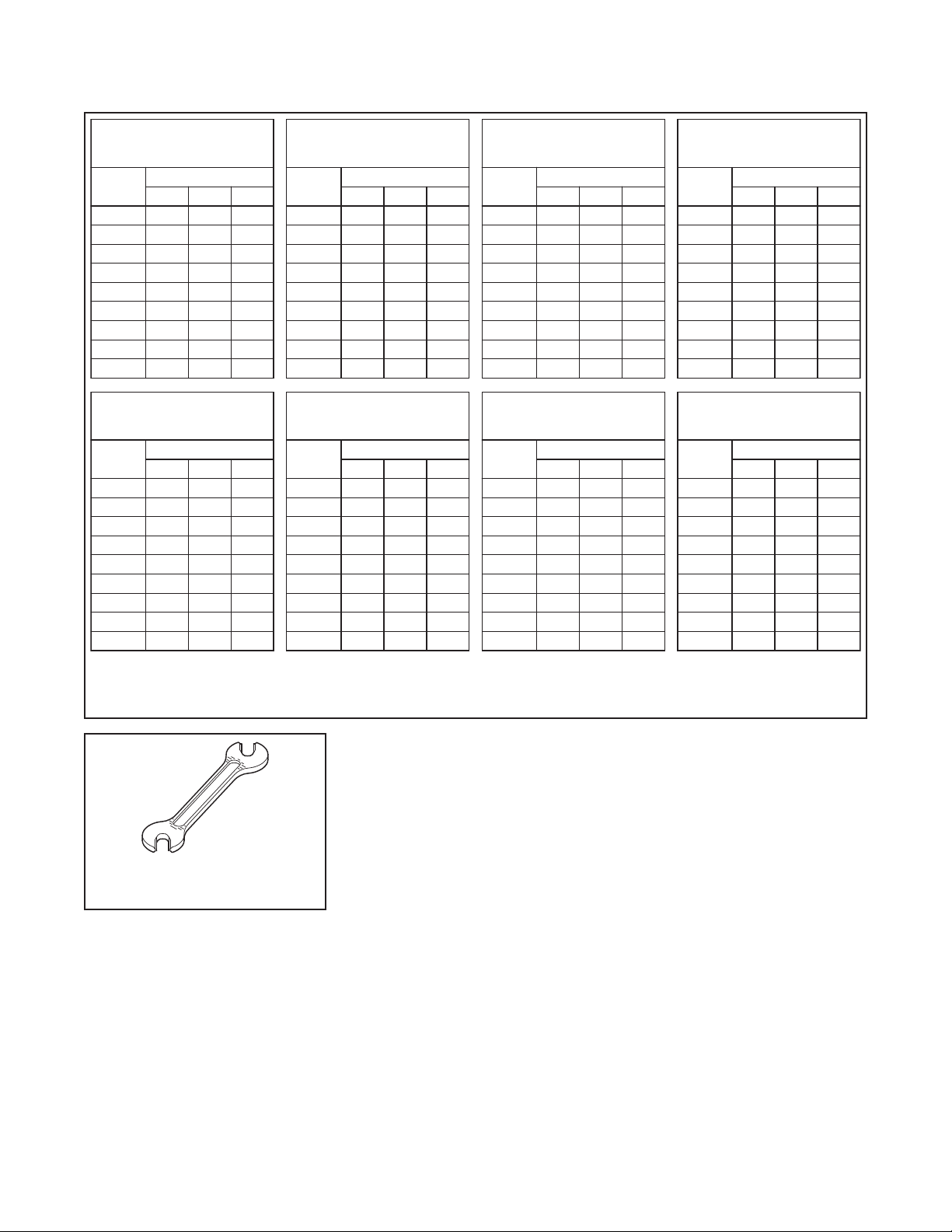
Discharge Coefficient
Refer to Table A
Spray Angles
Refer to Table B
Temperature Rating
Refer to Table C
Finish and Material
Refer to Table D
Thread Connection
1/2 inch NPT
Physical Characteristics
Frame ............................Bronze
Bushing (K=1.4 & K=2.8) . . . . . . . . . . . . . . Brass
Deflector..........................Bronze
Pin ...............................Brass
Bulb (11 mm dia.) . . . . . . . . . . . . . . . . . . . . Glass
Bulb Seats ........................Bronze
Spacer ...........................Bronze
Button............................Bronze
Spring Plates ......................Inconel
Gaskets ..........................Copper