Tyco KENDALL KANGAROO ePUMP User manual

Thank you for purchasing the KANGAROO ePump™ Enteral Feeding Pump. With proper care,
this device will provide you with years of precision service.
Merci d’avoir acheté la nutripompe entérale KANGAROO ePump™. Utilisé conformément
aux instructions fournies dans le présent manuel, ce dispositif fonctionnera avec précision
pendant des années.
Wir danken Ihnen dafür, dass Sie sich für den Kauf der KANGAROO ePump™-Pumpe für die
enterale Ernährung entschieden haben. Bei guter Pege leistet dieses Gerät jahrelange
Präzisionsarbeit.
Grazie per aver acquistato la pompa di nutrizione enterale KANGAROO ePump™. Se utilizzata
con attenzione, questo dispositivo funzionerà per anni in modo preciso.
Le agradecemos la compra de la bomba para alimentación enteral KANGAROO ePump™. Con
los cuidados apropiados, este dispositivo le brindará años de servicio de precisión.
Tack för ditt köp av KANGAROO ePump™ enteral matningspump. Med rätt skötsel
tillhandahåller denna produkt pålitlig kvalitet i många år.
Dank u voor de aanschaf van de KANGAROO ePump™ enterale voedingspomp. Als u dit
apparaat met de nodige zorg behandelt, blijft het u jarenlang accuraat en betrouwbaar van
dienst.
Obrigado por ter adquirido a Bomba de Alimentação Entérica KANGAROO ePump™. Com os
cuidados adequados, este dispositivo prestar um serviço de precisão durante muitos anos.
Monet kiitokset enteraalisen KANGAROO ePump™ -ravintopumpun hankinnasta.
Asianmukaisesti hoidettuna tämä laite kestää vuosia ja antaa tarkkoja mittaustuloksia.
Det glæder os, at De har anskaet en KANGAROO ePump™ pumpe til enteral ernæring. Når
denne pumpe vedligeholdes korrekt, får De eektiv drift i årevis.
Σα ευχαριστούε που αγοράσατε την Αντλία Εντερική Σίτιση KANGAROO ePump™. Με
την κατάλληλη φροντίδα, η συσκευή αυτή θα σα προσφέρει υπηρεσίε ακριβεία για πολλά
χρόνια.
Děkujeme vám, že jste si zakoupili pumpu pro enterální výživu KANGAROO ePump™. Při
správné péči vám toto zařízení bude roky bezchybně sloužit.
Köszönjük, hogy megvásárolta a KANGAROO ePump™ enterális táplálópumpát. Megfelelő
karbantartás mellett ez az eszköz évekig pontosan szolgálja a tulajdonost.
Благодарим вас за приобретение насоса для энтерального питания KANGAROO
ePump™. При должном уходе этот аппарат может эффективно работать в течение
многих лет.
KANGAROO ePump™ Enteral Besleme Pompasını satın aldığınız için teşekkür ederiz. Yeterli
özeni göstermeniz durumunda, bu cihaz size yıllar boyunca kesintisiz hizmet sağlayacaktır.
Takk for at du kjøpte KANGAROO ePump™ enterale ernæringspumpe. Med riktig stell gir
dette apparatet deg presis drift i årevis.
kENDALL
182531
™ Trademark of Tyco Healthcare Group LP or its affiliate.
™* SPRAY NINE is a trademark of Spray Nine Corporation.
™* PHISOHEX is a trademark of The Mentholatum Company.
™* HIBICLENS is a trademark of Regent Medical Limited.
™* VESTA-SYDE is a trademark of Steris Inc.
™* TYVEK is a trademark of E.I. DuPont De Nemours and Company
TYCO HEALTHCARE GROUP LP • 15 HAMPSHIRE STREET, MANSFIELD, MA 02048 • MADE IN U.S.A.
© 2008 TYCO HEALTHCARE GROUP LP • ALL RIGHTS RESERVED • 080821 • IN U.S. 1-800-962-9888 • www.tycohealthcare.com
TYCO HEALTHCARE U.K. LTD. • GOSPORT PO13 0AS, U.K.
0123
Enteral Feeding Pump
Service Manual
Nutripompe entérale
Manuel d’entretien
Pumpe für die enterale Ernährung
Service-Anleitung
per la pompa di nutrizione enterale
Manuale di manutenzione
Bomba para alimentación enteral
Manual de Servicio
Enteral matningspump
Servicemanual
Enterale voedingspomp
Servicehandleiding
Bomba de Alimentação Entérica
Manual de Instruções
Enteraalinen ravintopumppu
Huolto-opas
til pumpe til enteral ernæring
Servicehåndbog
Αντλία εντερικής σίτισης
Εγχειρίδιο Τεχνική Υποστήριξη
Pumpa pro enterální výživu
Servisní příručka
Enterális táplálópumpa
Szervízkönyv
Насос для энтерального питания
Руководство по эксплуатации
Enteral Besleme Pompası
Servis Kılavuzu
Enteral ernæringspumpe
Vedlikeholdshåndbok

ENG1
TABLE OF CONTENTS
Page
Section I General Information.................................................................................................................................................................................................. 1
Section II Safety and Warnings ................................................................................................................................................................................................. 2
Section III Icons, Specications, and Conformity..................................................................................................................................................................... 3
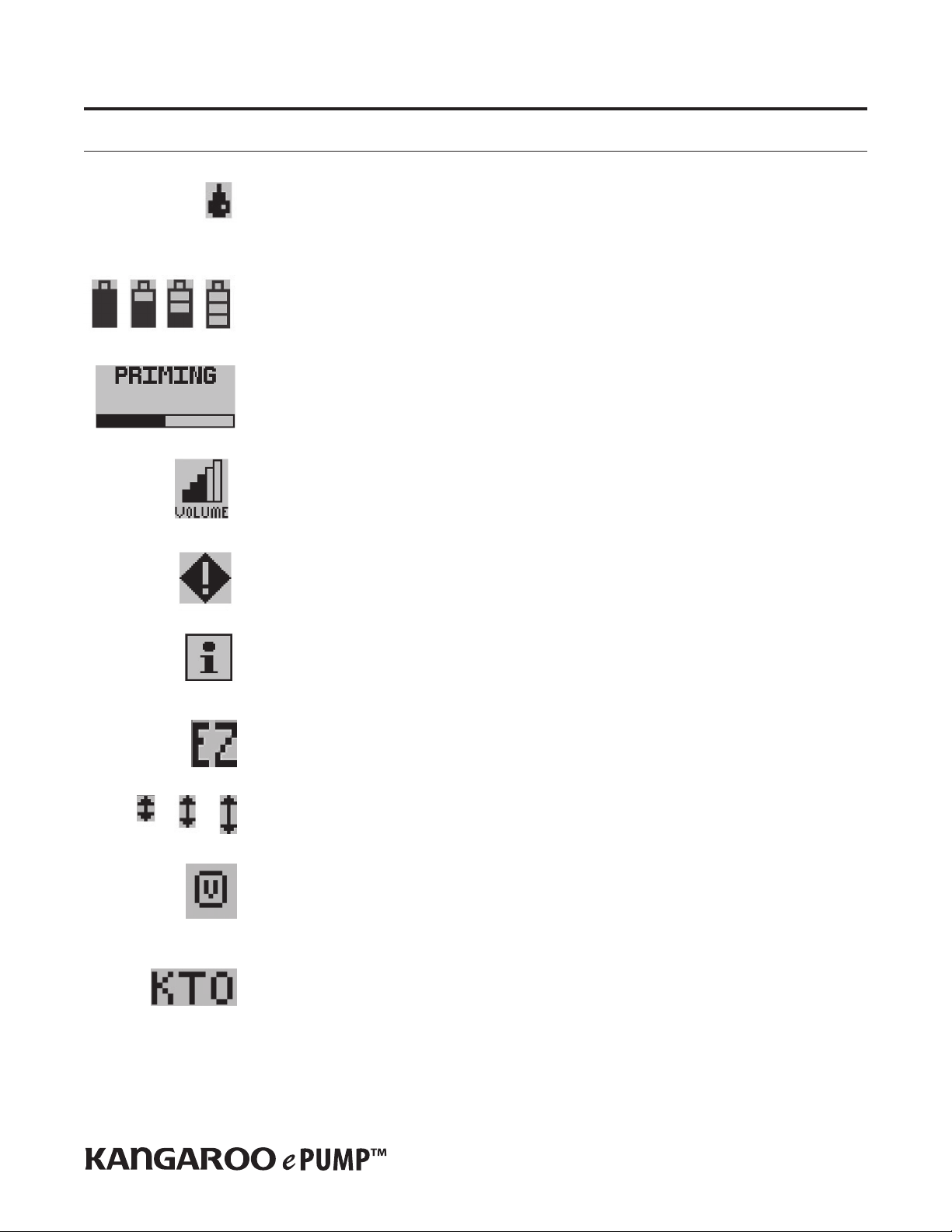
Icon Information............................................................................................................................................................................................................ 3
Specications................................................................................................................................................................................................................. 4
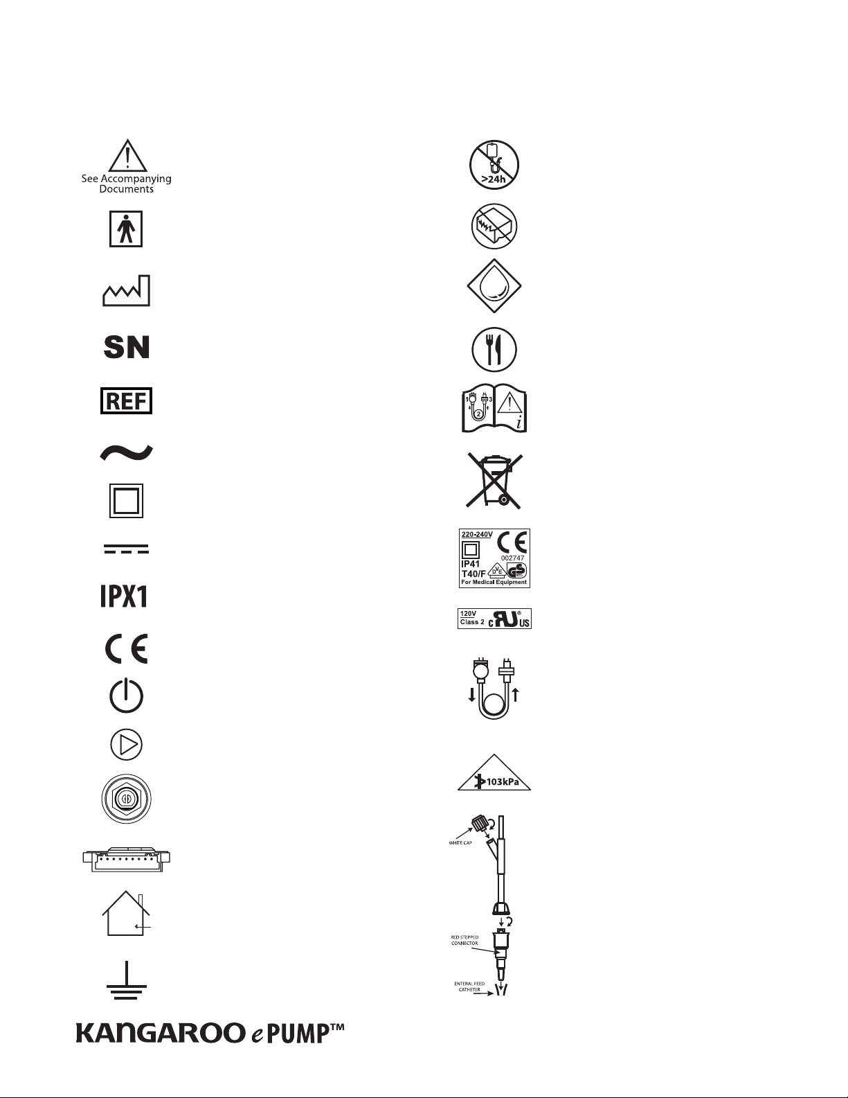
Symbols on Pump and Accessories................................................................................................................................................................................. 5
Electromagnetic Conformity Declaration ....................................................................................................................................................................... 6
Section IV Cleaning Procedures.................................................................................................................................................................................................. 7
Section V Operating Procedures................................................................................................................................................................................................ 8
Initial Setup ................................................................................................................................................................................................................... 8
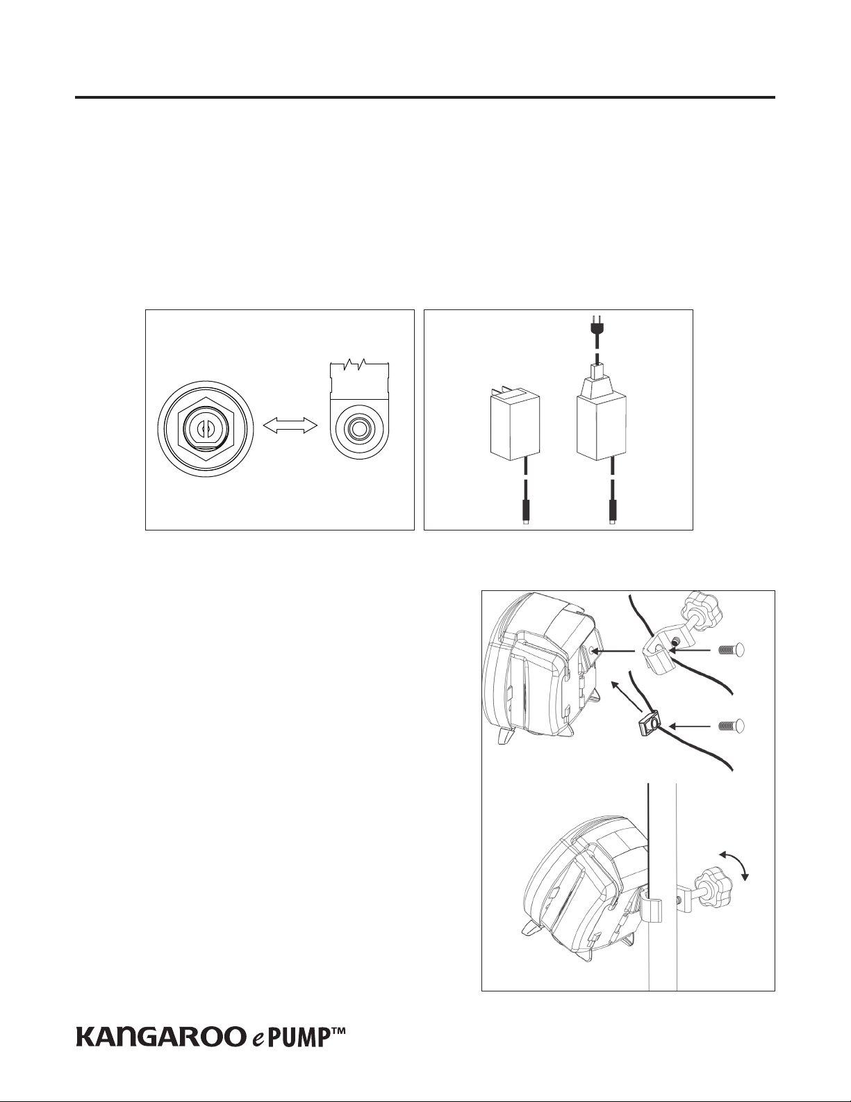
Attaching the A/C Adapter Power Cord.......................................................................................................................................................................... 8
Battery Setup................................................................................................................................................................................................................. 8
Attaching Pole Clamp .................................................................................................................................................................................................... 8
Instructions for Use........................................................................................................................................................................................................ 9
Quick Start ..................................................................................................................................................................................................................... 9
General Startup.............................................................................................................................................................................................................. 9
Placement/Mounting .................................................................................................................................................................................................... 9
A/C Power Operation ..................................................................................................................................................................................................... 9
Battery Power Operation ............................................................................................................................................................................................... 9
Power On/O................................................................................................................................................................................................................. 9
Language Selection, First Power Up.............................................................................................................................................................................. 10
Keep or Clear Prior Pump Settings ................................................................................................................................................................................ 10
Section VI Error Codes and Troubleshooting Guide................................................................................................................................................................ 10
System Error ................................................................................................................................................................................................................. 10
Hold Error...................................................................................................................................................................................................................... 11
Rotor Error .................................................................................................................................................................................................................... 11
Feed Error ..................................................................................................................................................................................................................... 11
Flush Error..................................................................................................................................................................................................................... 11
Flow Error ..................................................................................................................................................................................................................... 11
Pump Set Dislodged Error............................................................................................................................................................................................. 11
Battery Low .................................................................................................................................................................................................................. 11
Feeding Complete......................................................................................................................................................................................................... 11
Pump Set Use >24 Hours Warning ...............................................................................................................................................................................11
LED Array ...................................................................................................................................................................................................................... 11
Section VII Re-Certication of Performance Test..................................................................................................................................................................... 12
Section VIII Re-Certication Troubleshooting Guide................................................................................................................................................................ 12
Section IX Re-Certication Test Documentation .................................................................................................................................................................... 14
Section X Pump Flow Accuracy Test......................................................................................................................................................................................... 14
Section XI Maintenance.............................................................................................................................................................................................................. 15
Section XII Assembly Diagrams and Reorder Numbers........................................................................................................................................................... 18
Assembly Diagrams ...................................................................................................................................................................................................... 18
Serviceable Parts Table................................................................................................................................................................................................. 23
Accessory Table............................................................................................................................................................................................................. 23
Section XIII Customer Service....................................................................................................................................................................................................... 24
Section XIV Warranty .................................................................................................................................................................................................................... 24
Section XV AccuSystem√TM........................................................................................................................................................................................................... 24
This product contains software solely owned by Tyco. Tyco grants the user a non-exclusive, limited license to use the software according to the operating instructions. A copy of the
license can be obtained from Tyco.
EN

ENG2
Figure 1A. KANGAROO ePump features, front and rear views. Figure 1B. KANGAROO ePump Pump Set loading area.
'FFEJOH4FU
-PBEJOH"SFB
1PMF$MBNQ
'FFEJOH4FU$BQUVSF
Section I – General Information
The KANGAROO ePumpTM enteral feeding pump is a simple-to-use, precision enteral feeding pump. It is easily programmed to provide patients with either continuous or
intermittent feeding, and can provide automatic ushing capability when used with KANGAROO ePump Feed & Flush Sets.
User Interface:
• Intuitive user interface
• Large, backlit LCD display
• Step-by-step prompts to guide programming and operation
• Stoplight LED array visually indicates pump status in a bright or darkened room
Ergonomics:
• Quiet operation
• Compact, portable design
• Tabletop usage , IV pole mounting or backpack
• Simple loading of Pump Sets
• Transparent side door to protect Pump Set
• Integrated handle for easy transport
Features:
• MISTIC (Magnetic Intelligent Set Type Identication Connector) Feed-Only vs. Feed & Flush Set identication system to ensure match between the pump’s user interface and
Pump Set type
• Automatic Anti-Free-Flow (AFF) System
• Audible alarm to indicate errors or Pump Set loading conditions
• Orientation-independent design eliminates need for drip chamber on pump set
• Sensor technology detects both upstream and downstream ow conditions
• Continuous feed, intermittent feed, and ush capability
• Auto-prime feature reduces the need for time-consuming manual priming
• Hold feature with restart and Keep Tube Open (KTO) feature
• Stores previous 72 hours of feeding and ushing history
• 15 languages
Service:
• Serial I/O port for data retrieval and software updates
• Uses replaceable, rechargeable NiMH Battery Pack for 15 hours of backup power
• Removable Power Cord
Menu
Selections
Menu
Selection
Buttons
Graphic
Display
Feeding Set Cap
Storage Area
Front
Door
Back
Battery
Compartment
Serial I/O Port
A/C Adapter Port
Pole Clamp
Attachment Point
Integrated Handle
Battery Status
Power Button
Output Totals
Input Settings
Status LEDs
Status Line

ENG3
Section II — Safety and Warnings
CAUTION: U.S. federal law restricts the sale of this device to physicians or to their direct representatives.
1. Read this booklet thoroughly before using the KANGAROO ePump enteral feeding pump.
2. Do not use this device near ammable anesthetics.
3. Disconnect power supply before cleaning or servicing.
4. Use only KANGAROO ePump enteral feeding pump Power Cord (with built-in A/C adapter) with pump. See Section XII - Assembly Diagrams and Reorder Numbers.
5. Use only KANGAROO ePump enteral feeding pump Pump Sets with this device. Pump is not compatible with other Pump Sets.
6. For re-certication, see Section VII- Re-certication of Performance. For other integrity checks, consult with a qualied Biomedical technician or contact the manufacturer
(Section XIII- Customer Service).
7. For service or for technical information, please contact Customer Service (Section XIII).
8. Dispose of old battery-powered electronic equipment in a manner consistent with institutional policy for expired equipment disposal.
9. Cleaning frequency and practices must be consistent with institutional policy for cleaning of non-sterile devices. See Section IV - Cleaning, for instructions on cleaning the
KANGAROO ePump enteral feeding pump.
10. For additional safety information relating to icon descriptions, specications and/or symbols, see Section III - Icon, Specications, and Conformity.
11. This device is designed to minimize the eects of uncontrolled electromagnetic interference and other types of interference from external sources. Avoid use of other
equipment that may cause erratic operation or degradation in the performance of this device.
12. WARNING: The serial I/O port (see Figure 1A) is intended only to be used with a specically certied accessory to retrieve/extract certain information from the pump. This
accessory is specically certied as complying with the safety requirements of accessories used with the pump, whereas the safety certication of the accessory has been
performed in accordance with IEC 60601-1 and as appropriate the IEC/EN 60601-1 harmonized standard.
Any accessory equipment that can be connected to the DB9 Serial I/O port, and which does not comply with the equivalent safety requirements of this equipment, may lead
to a reduced level of safety of the pump. While use of the pump’s DB9 port is not recommended for customers, the following should be considered in the event that the
customer decides to connect to this port:
The accessory is specically certied as complying with the safety requirements for accessories used with the pump, whereas the safety certication of the accessory has been
performed in accordance to the appropriate IEC 60601-1 and/or IEC 60601-1-1 harmonized standard.
13. CAUTION: This enteral feeding pump should only be used for patients who can tolerate the ow rates and accuracy levels delivered by the pump. Premature infants may
require higher accuracy rates than specied for this enteral feeding pump. For optimal accuracy, the bottom of the formula container should be 18” above the pump, do not
reuse feeding sets and avoid over stretching the silicone tube that wraps around the pump’s rotor.
14. Do not attempt to rotate the valve stem inside the feeding set valve assembly. Rotation of the valve stem can only be done by the pump while the valve assembly is properly
loaded into the pump.
15. Should feeding sets require rinsing, it is recommended that the feeding sets be rinsed while they are loaded in the pump. Should the removal of the feeding set valve
assembly be desired, power the pump o and wait ve seconds before removing. Upon re-insertion of the feeding set valve assembly, make sure the valve assembly is
properly loaded into the pump.

ENG4
Run Mode Vertically-moving droplet in RUNNING screen indicates Run mode.
Battery Symbols • Full charge
• 2/3 or less charge
• 1/3 or less charge
• Very low battery (15 minutes max.)
Auto Priming Indicator When auto priming, the bar will progress to show auto prime feature is active.
Volume Setting Indicates alarm volume setting.
Error Indicator Pump operations are stopped until the error is resolved.
Information Indicator This indicates information only and does not require any immediate action.
EZMODE Indicator Indicates that EZMODE feature is turned on.
Communication Indicator Indicates that communication feature is turned on.
Volume to be Delivered Indicator Indicates that VTBD feature is turned on.
Keep Tube Open Indicates that Keep Tube Open feature is turned on.
Section III – Icons, Specications, and Conformity
Icon Identication

ENG5
Specications and Symbols
Specications
UL Listing Medical Electrical Equipment
KANGAROO ePump™ Enteral Feeding Pump
(1) Classied with respect to electrical shock, re, and mechanical hazards in accordance with UL60601-1.
(2) Classied with respect to electrical shock, re, mechanical and other specied hazards in accordance with CAN/CSA C22.2 No. 601.1
Type Infusion Device Volumetric
Pumping Mechanism Rotary Peristaltic
Pump Sets KANGAROO ePump MISTIC Feed-Only Set or Feed & Flush Set
Feeding Formula Delivery Rate 1-400 mL/hr in 1 mL increments
Feeding Formula VTBD 1-3000 mL in 1 mL increments
Bolus Volume 1-3000 mL in 1 mL increments
Number of Boluses 1-99
Bolus Interval 1-24 hours in 1-hour increments
Flushing Solution Dose Range 10-500 mL in 1 mL increments
Flushing Solution Interval Range 1-24 hr in 1 hr increments
Accuracy ±10% or 0.5 mL/hr, whichever is larger, with bottom of bag at 46 cm (18”) above the top of the pump, at room temperature 22° C ± 2° C
(72° F ± 3° F), using a new pump set.
Occlusion Pressure 15 psi (103 kPa) Nominal
Dimensions Height: 16.8 cm (6.6”) Width: 16.3 cm (6.4”) Depth: 11.7 cm (4.6”)
Weight 1.1 kg (2.4 lbs), 1.2 kg (2.7 lbs) with pole clamp
Material Housing: ABS/Polycarbonate blend
Pump Set Door: Polyester/ Polycarbonate blend
Power Use AC adapter for wall outlet usage. Pump operates on 9V DC, 1.5 Amps.
Battery New, fully charged NiMH Battery Pack delivers ≥ 15 hrs at 125 mL/hr feed rate.
Approximately 15 minutes prior to complete battery discharge, a low battery alarm will occur (see subsection “Battery Low” in Section
VI). When complete discharge occurs, the pump will automatically turn itself o. The battery will charge continuously whenever the
pump is plugged into a wall outlet. Eight hours of charging is required to fully recharge the battery pack.
Alarms
System Error
Flow Error
Pump Set Dislodged Error
Hold Error
Rotor Error
Feed Error
Flush Error
Battery Low
Alarm Volume Minimum of 70 dBA at 1 meter in maximum volume orientation
Operating Temperature 10° - 40° C (50° - 104° F) 75% R.H. non-condensing
Storage Temperature 0° - 50° C (32° - 122° F) 95% R.H. non-condensing
Type of Protection Against Electrical Shock Class II, Internally-powered Equipment
Degree of Protection Against Electrical Shock Type BF
Mode of Operation Continuous or programmed intermittent operation
Degree of Protection Against Ingress of Fluids Drip-proof-IPX1

ENG6
13
2
Refer to Accompanying Documents
Type BF Protection (Degree of protection
against electrical shock - there is no conductive
connection to the patient)
Manufacturing Date Code
Serial Number
Reorder number for the device located on the
carton label
Alternating Current
Class II Equipment (degree of protection against
electrical shock), Double Insulated
Direct Current (DC)
Drip Proof (Degree of protection against ingress
of uids)
CE Mark – European Community Certication
Power Button
Buttons for Selecting Screen Prompts
Power Source 9V DC 1.5 Amp
DB9 Serial I/O Communication Port (Certication
and Programming)
Caution: For indoor use only
Functional Ground
Symbols on Pump and Accessories
The following symbols are found on the pump or on the accessories, such as the A/C adapter.
Do not use KANGAROO ePump enteral feeding
pump Feeding Sets for greater than 24 hours
Do not use if unit package is open or damaged
Flushing Solution
Feeding Formula
See KANGAROO ePump Manual for Feeding Set
loading instructions
European Union’s Waste Electrical and Electric
Equipment (WEEE) Directive in accordance with
European Standard EN 50419
VDE in Europe
UL in USA and Canada
Set Loading Diagram
Maximum operating pressure 103 kPa
Assure that the white cap and red stepped
connector are securely tightened

ENG7
Emissions Test Compliance Electromagnetic Environment - Guidance
RF emissions
(CISPR 11) Group 1
RF emissions
(CISPR 11) Class B
Harmonic emissions
(IEC 61000-3-2) Class A
Voltage uctuations/ icker emissions
(IEC 61000-3-3) Complies
Radiated Disturbance Immunity
(EN60601-1-2 / IEC 61000-4-3:2002) Complies
Conducted Disturbance Immunity
(EN60601-1-2 / IEC 61000-4-6:2001) Complies
Power Frequency Magnetic Field Immunity
(EN60601-1-2 / IEC 61000-4-8:2001) Complies
Voltage dips and sags Immunity
(EN60601-1-2 / IEC 61000-4-11:2001) Complies
Electrical FastTransient / Bursts Immunity
(EN60601-1-2 / IEC 61000-4-4:2001) Complies
Electrostatic Discharge Immunity
(EN60601-1-2 / IEC 61000-4-2:2001) Complies
Surge Immunity
(EN60601-1-2 / IEC 61000-4-5:2001) Complies
The KANGAROO ePump enteral feeding pump
uses RF energy only for its internal function.
Therefore, its RF emissions are very low and are
not likely to cause any interference in nearby
electronic equipment.
The KANGAROO ePump enteral feeding pump is
suitable for use in all establishments, including
domestic establishments and those directly
connected to the public low-voltage power
supply network that supplies buildings used for
domestic purposes.
Electromagnetic Conformity Declaration
The KANGAROO ePump enteral feeding pump has been built and tested according to UL60601-1, E189131 CSA-C22.2 No.601.1-M90, and EN60601-1-2 Standards.
The KANGAROO ePump enteral feeding pump is intended for use in the electromagnetic environment specied below. The user of the pump should assure that it is used in such an
environment.

ENG8
Section IV — Cleaning Procedures
Cleaning should be performed as needed. It may also be desirable to dene cleaning intervals based on knowledge of the environment in which the pump is used. Only personnel
trained in the cleaning of medical devices should perform cleaning.
CAUTION: Do not immerse pump or power cord in water or other cleaning solution; clean using a damp (not wet) cloth or sponge. Failure to follow the cleaning procedures
described herein could result in hazards to users. As with any AC powered electrical device, care must be taken to prevent liquid from entering the pump to avoid electrical shock
hazard, re hazard, or damage to electrical components.
If any of the following events occur, DO NOT USE the pump until it has been properly cleaned and serviced by personnel trained in servicing KANGAROO ePump enteral feeding
pumps:
• wetting of the pump’s power cord or leakage into the pump interior during cleaning.
• spillage of large amounts of formula onto the pump exterior, or any spillage onto the power cord.
General Cleaning Directions
Cleaning of KANGAROO ePump enteral feeding pumps must be performed as follows:
CAUTION: Disconnect pump from AC power source before cleaning. After cleaning, do not connect to AC power source until pump and power cord are thoroughly dry.
• A mild detergent should be used for general cleaning. If necessary, the pump may be cleaned with a 10:1 water and hypochlorite mixture, however, repeated cleaning with this
solution can damage the plastic pump case. Isopropyl alcohol, applied with a damp (not wet) cotton swab, may be used for cleaning dicult-to-reach areas, however, it should
be used sparingly because repeated cleaning may damage the case.
• DO NOT USE strong cleaners such as Spray Nine™*, Phisohex™*, Hibiclens™*, or Vesta-Syde™* because damage to the pump case housing can result.
Directions for Cleaning Pump Housing
• Refer to General Cleaning Directions before starting.
• Clean outside surface with a damp (not wet) cloth or sponge and keep pump in upright position as much as possible.
• Avoid excess moisture near pole clamp area.
• Do not allow cleaning solution to enter the vertical vents in the housing, underneath the handle.
Directions for Cleaning Pump Power Cord
• Refer to General Cleaning Directions before starting.
• Unless soiling is observed, the power cord should not be cleaned.
• If cleaning of the power cord is necessary, unplug from outlet and wipe the exterior surfaces of the wall plug with a cloth dampened with isopropyl alcohol.
CAUTION: Avoid exposing power cord to excess moisture, as this can lead to an electrical shock or re hazard.
Directions for Cleaning Rotor Assembly
• Refer to General Cleaning Directions before starting.
• Open the blue door enclosing the pump set loading area.
• Loosen rotor set screw with 5/64” (2 mm) Allen wrench and gently pull rotor o shaft. After removing rotor, avoid getting any moisture in the rotor shaft opening.
• Clean rollers thoroughly with warm soapy water, or isopropyl alcohol if necessary.
• Be sure all parts of rotor are completely dry before putting it back onto shaft.
• To replace rotor, align set screw on hub of rotor with the attened section of the output shaft.
• Push rotor into place and tighten set screw (do not over tighten).
Preventative Maintenance
This pump must be periodically re-certied to assure proper functioning and safety. The recommended service interval is at least once per year. Re-certication may be done at the
user’s Biomedical Engineering Department, an outside service, or by Tyco Healthcare Group LP Factory Service. To arrange for Tyco Healthcare Group LP Factory Service in the US,
call 1-800-448-0190. In Canada, call 1-877-664-TYCO (8926). Outside of the US and Canada, please contact your local Customer Service for more information.
If a pump malfunctions, please contact your Tyco Healthcare Group LP Representative or call Customer Service for instruction.

ENG9
Section V — Operating Procedures
The information provided in this section is limited to basic set-up and function and does not describe all capabilities of the KANGAROO ePump enteral feeding pump. For a detailed
operating procedure, please refer to your KANGAROO ePump enteral feeding pump Operation and Service Manual.
Initial Setup
Attaching the A/C Adapter Power Cord
Plug the Power Cord into the A/C Adapter Port on the back of the pump. See Figure 1A to locate port on pump. Make note of the location of the pins and tab on the plug to properly
orient the plug
The connector, which attaches to the back of the pump, has a spring-loaded locking sleeve that locks into the pump, thus helping to prevent the connector from being accidentally
unplugged from the pump. To remove the connector, grasp the outer sliding sleeve member and pull. Do not detach the connector by pulling on the cord only.
(A cord extension accessory is available that will allow the wall plug to be separated from the power transformer, see Fig. 2B. The cord extension order number is located in Section
XII - Assembly Diagrams and Reorder Numbers.)
Battery Setup
The battery pack is fully charged before shipping, and is left unconnected to optimally preserve
battery life.
WARNING: The battery should be connected before using the pump.
It is also recommended that the battery charge be “topped o” before battery-only operation is
utilized. The battery pack will charge continuously whenever the pump is plugged into a wall
outlet, including during normal use of the pump with A/C power. Eight hours of charging is
required to fully recharge the battery pack.
A new battery pack will provide approximately 15 hours of service before needing to be recharged.
Attaching Pole Clamp
The KANGAROO ePump enteral feeding pump can be attached to a vertical pole using the Pole
Clamp, included with the pump. The pole clamp provides the ability to retain the power cord
to prevent accidental cord removal or cord loss. Simply place the power cord into the U-shaped
groove located on the back of the pole clamp as shown in Fig. 3 and attach the pole clamp to the
KANGAROO ePump enteral feeding pump. Be sure not to pinch the power cord or damage the cord
insulation when installing.
To attach the Pole Clamp to the KANGAROO ePump enteral feeding pump, align the hole on
the Pole Clamp with the mounting hole on the back of the pump. Use a 3/8” - 16 bolt to fasten
together, as shown in Figure 3.
Figure 3. Attaching and using the Pole Clamp or Cord Clip.
Figure 2A. Alignment of A/C Adapter plug with pump’s
adapter port.
AC Adapter
Plug
AC Adapter
Port
scale 2:1
Use care aligning adapter with pump
connector
AC Adapter Port AC Adapter Plug
Figure 2B. Cord Extension Accessory

ENG10
Instructions for Use
Quick Start
1. Press POWER on lower, right-hand corner of control panel.
2. Open blue door enclosing pump set loading area.
3. To load pump set (refer to Figure 4):
• Grasp nger tab on valve and insert into left pocket (1).
• Grasp black ring retainer and gently stretch tubing around rotor (2).
• Pull up on retainer and insert into right pocket (3).
• Avoid over stretching the silicone tube.
• Press down on nger tab to ensure that valve is fully seated. Finger tab should align with locating rib.
• Close blue door. (Note: display status line should read SET LOADED).
4. Suspend the pump set so that the bottom of the formula container is 18” above the pump.
5. To automatically prime the pump, press 4PRIME PUMP and 4AUTO PRIME. For Feed & Flush sets, auto priming will prime both lines.
6. To directly control pump priming, press 4PRIME PUMP and then press and hold the
4HOLD TO PRIME button(s). If a Feed & Flush Set is used, remember to rst press 4HOLD TO PRIME FLUSH until the ushing uid has reached the valve, and then press
4HOLD TO PRIME FEED until the feeding uid has reached past the valve and down to the distal end connector.
7. Use buttons4on left side of LCD to set the feeding parameters. Set ushing parameters if a Feed & Flush Set is loaded. The continuous or intermittent feed mode selection
is made under the MORE options menu.
8. Press 4RUN when ready to start. The screen will display RUNNING.
9. To stop, press 4HOLD or press and hold the POWER button.
General Startup
Placement/Mounting
There are two recommended placement methods for the KANGAROO ePump enteral feeding pump.
• Attached to a vertical IV pole via the Pole Clamp peripheral device, included with the pump.
• Placed feet down on any horizontal surface.
A/C Power Operation Plug the KANGAROO ePump enteral feeding pump into an A/C power outlet for normal operation. When the pump is not
plugged in, or if A/C power is interrupted, a built-in rechargeable battery will run the pump.
Battery Power Operation If A/C power is not available to the pump, or if A/C power is interrupted, the pump will automatically operate on backup
battery power. The built-in battery recharges any time the pump is plugged into an outlet. A fully-charged, new battery
will supply 15 hours of backup power at 125 mL/hr before requiring recharging. Contact Customer Service, Section XIII, to
replace the Battery Pack if battery life degrades.
Power On/O To power up the pump, press the POWER button on the lower right of the front panel. To power down the pump, press and
hold the POWER button until the pump display turns o.
Figure 4. Installation of Pump Set
13
2
Black Ring
Retainer
(MISTIC)
Finger
Tab
Valve
Rotor

ENG11
The system error is the most general form of error. The
only way to exit from a System Error is to power down
the pump. Turn the pump o and back on to try to clear
the error. If the error cannot be resolved in a timely
manner, power the pump down and contact Technical
Service. The error number displayed on the screen will
reference the type of System Error.
System Error
SYMPTOM PROBABLE CAUSE CORRECTIONS
0 Internal timer stopped.
1 Flash Chip missing OR version incompatible.
2 Too many graphic screens in memory.
4 Never got a ADC ISR for motor current.
5 Never got a ADC ISR for battery level.
6 Never got a ADC ISR for battery temperature.
7 Never got a ADC ISR for Ultrasonic Upstream Occlusion or Bag-
Empty checks.
8 Never got a ADC ISR for Ultrasonic during Downstream
Occlusion.
9 RS232 Communications Transmission Error.
10 Flash Write Error.
11 Flash Read Error.
12 General Stopcock Time Out.
13 Time Out for Buzzer Test
16 Flash Screen Read Error.
19 Flash Languages Read Error.
20 Could not nd Stop Cock Flush Position during prime routine.
21 Could not nd Stop Cock Feed Position during prime routine.
22 Motor Error during Tubing Auto Load.
23 Motor Failsafe Time Out Error. Possible damaged gearbox
encoder or ex cable.
25 Display Lockup Time Out Error.
33 Motor Control Failure.
Language Selection, First Power Up Immediately after powering up the pump for the rst time, the language option screen will appear. Select the language
using the ( ) or ( ) buttons. When the language is selected, push the fth button to enter the language selection.
After the language is selected the rst time the pump is powered up, the language selection screen will not appear during
future power up operations. Should the language need to be changed after the initial power up, it can be changed through
the “MORE OPTIONS” menu.
Keep or Clear Prior Pump Settings Immediately after powering up the pump, if the prior feed or ush settings were not cleared and the settings are not locked
in the BioTech Screen, the pump will give the following two options:
KEEP SETTINGS Select this option to start with the same settings that were most recently programmed into the pump.
Any of the previously-programmed settings can be modied, if needed. The feed volume totals, “mL FED” (Continuous Feed
Mode) or “BOLUSES FED” (Intermittent Feed Mode) and “mL FLUSH” are also maintained. If a VTBD has been set, the VTBD
setting originally programmed will not change, however, volume to be delivered will start over at one mL.
CLEAR SETTINGS Select this option to reset all input feeding settings and the output feed totals to zero. It will then be
necessary to program all settings before running the pump. The BioTech options settings will not change.
Section VI — Error Codes and Troubleshooting Guide
For operational errors, the KANGAROO ePump enteral feeding pump display will show the error indicator icon, with specic information regarding the error condition, and will
sound the alarm.
The following conditions will trigger error conditions and will activate audible and visible alarms:
• Feed or Flush containers are empty
• Feed or Flush tube becomes occluded between bag and pump
• Tube becomes occluded between pump and patient
• Battery low (alarm beeps continuously, about 15 minutes before shut-o)
• Unit is left in HOLD mode longer than 10 minutes without input
• Pump set tubing is improperly loaded around the rotor
• Feeding complete
• The MISTIC connector is removed during AUTOPRIMING or RUNNING
• System errors, see Table below
Troubleshooting Guide Listed below are some of the probable causes of alarm conditions and their corrections

ENG12
Pump has been inactive without input for more than 10 minutes.
The Rotor Error screen appears during RUNNING or PRIMING, when the pump
has detected an unusual operating condition for the rotor. The Rotor Error
generally results from a problem with the Pump Set tubing around the rotor.
The Feed Error screen appears when the enteral formula is no longer being
delivered because the bag is empty or because of a clog between the pump
and the bag.
The Flush Error screen appears when the ushing solution is no longer being
delivered because the ush bag is empty or because of a clog between the
pump and ush bag.
The Flow Error screen appears when either the feeding or the ushing
solution is no longer being delivered because of a clog between the pump
and the patient.
The Pump Set Dislodged screen will appear if the black ring retainer (MISTIC)
is not properly loaded in the MISTIC pocket in the pump set loading area.
The Battery Low screen appears and the alarm beeps continuously when the
battery needs to be recharged. There is approximately 15 minutes of battery
life remaining when this screen appears.
The Feeding Complete information screen appears after completion of the
programmed feeding.
The pump set usage warning indicator will blink on the RUNNING screen if a
pump set has been used for 24 or more hours (hours actually running).
The pump status LED array on the upper right of the pump gives a quick
visual indication of the pump status, especially in darkened rooms.
Hold Error
Rotor Error
Feed Error
Flush Error
Flow error
Pump Set Dislodged Error
Battery Low
Feeding Complete
Pump Set Use > 24 Hours
LED Array Warning
SYMPTOM PROBABLE CAUSE CORRECTIONS
Press CONTINUE to return to the previous screen
Check that the pump set is not damaged and re-load the tubing
around the rotor as described in subsection “Loading Pump Sets”.
Press CONTINUE to restart the pump.
Check the feed line to nd the occlusion causing the blockage. If
the occlusion cannot be cleared, load a new pump set, prime it, and
press CONTINUE to restart the feeding.
Check the ush line to nd the occlusion causing the blockage. If
the occlusion cannot be cleared, load a new pump set, prime it, and
press CONTINUE to restart the feeding.
Check the line to nd the occlusion causing the blockage. If the error
cannot be resolved, check the valve pocket in the pump set loading
area for dampness or dirt, which may be a cause for a false error.
Clean and dry the valve pocket. If the error still cannot be resolved,
load a new pump set, prime it, and press CONTINUE to restart the
feeding.
Check and correct the positioning of the MISTIC retainer if possible.
If the error cannot be resolved, load a new pump set, prime it, and
press CONTINUE to restart the feeding
Plug the power cord in to begin recharging. The pump will
automatically return to the screen that was active prior to the error.
The battery will charge continuously whenever the pump is plugged
into a wall outlet. 6 hours of charging is required to fully recharge
the battery pack.
Press Power Down to turn o the pump. Press CONTINUE to return to
the SET LOADED opening menu.
It is recommended to replace pump sets after this length of usage.
This icon is only an informational message and does not require
action.
A green light status indicates normal pump operation and does not
require action.
A yellow light status indicates an informational or warning situation
for a low battery condition, the pump in HOLDING mode, or one of
the following errors: HOLD ERROR, FEED ERROR, FLOW ERROR, and
FLUSH ERROR.
A red light status indicates a critical pump error. The screen will
show one of the following error messages: SYSTEM ERROR, PUMP
SET DISLODGED, or ROTOR ERROR.

ENG13
Section VII – Re-Certication of Performance
System Performance Re-Certication
Clean the KANGAROO ePump Enteral Feeding Pump as described in Section IV. Inspect the exterior housing and power cord for damage prior to performing the Re-Certication
Test.
CAUTION: Disconnect pump from AC power source before cleaning. After cleaning, do not connect to AC power source until pump and power cord are thoroughly dry.
Do not immerse pump or power cord in water or other cleaning solution; clean using a damp cloth or sponge. Failure to follow the cleaning procedures described herein could
result in hazards to users. As with any AC powered electrical device, care must be taken to prevent liquid from entering the pump to avoid electrical shock hazard, re hazard, or
damage to electrical components.
DO NOT use strong cleaners such as Spray Nine™*, Phisohex™*, Hibiclens™*, or Vesta-Syde™* because damage to the pump case housing can result.
NOTES:
Refer to Figure 1A for visual description of product.
Refer to Figure 1B for example of properly loaded feeding set.
It is recommended this Re-Certication test be completed every two years. Use a KANGAROO Re-Certication Pump Set, Item Code 776150.
The directions are as follows:
1. Power down pump if on.
2. Fill Re-Certication Burette to top of line as indicated with water.
3. Hang Re-Certication Burette with ll mark exactly 18” (46 cm) to the top of the pump.
4. Place outlet connector into drain at a level even with the bottom of pump.
5. Open blue door enclosing feeding set loading area.
6. To load Re-Certication Set:
• Grasp thumb tab on valve and insert into left pocket.
• Grasp black ring retainer and gently stretch tubing around rotor and insert retainer into right pocket.
• Press down on thumb tab to ensure valve is fully seated.
7. Close blue door.
8. Press POWER button on control panel.
NOTE: Display should read MANUAL TEST.
9. Individually select each menu item and follow screen prompts for that item.
NOTE: Each of the rst 4 menu items must be successfully completed prior to START AUTO TEST.
NOTE: During MISTIC TEST, lift black ring retainer SLOWLY from its pocket. Listen for tone and release retainer. If unsuccessful, repeat operation.
10. Upon completion of auto test procedure display will indicate whether pump has passed of failed re-certication.
CAUTION:
The manufacturer recommends an electrical safety test be performed on the unit if the pump has been opened, serviced internally and/or uid ingress is suspected in the pump.

ENG14
Section VIII – Re-Certication Troubleshooting Guide
For re-certication failures, the KANGAROO ePump enteral feeding pump display will list a set of two numbers. The top number indicates the actual failure whereas the bottom
number indicates the failure value. Using the re-certication failure codes table below the user can troubleshoot re-certication failures by cross-referencing the numerical read-
out on the failure screen with the linked failure listed in the table below
Description Code Probable Causes of Failure Min Max Input Units Output Units
Pass Fail 0 Another Test has failed Status Status
Timeout Code 39 N/A Special Code for premature failure, see description in Obtain Data screen section. Code Code
(Manual Tests) 1-4 The listed manual test was not completed (Buzzer, LED, Battery, MISTIC) Status Status
BuzzerVADC 5 If too low buzzer is too weak, if too high buzzer has short circuit or other circuit
board problem causing high buzzer feedback signal 35 200 Counts Voltage (V)
BuzzerFDAC 6 N/A 169 203 Counts Frequency (Hz)
USDryVADC 7 Water drops left in tube, or high ultrasonic sensor crosstalk 0 5 Counts Voltage (V)
USDryFDAC 8 N/A 98 210 Counts Frequency (MHz)
HomeSlot1 9 Open circuit connections in motor or ex cable, valve of set not seated properly,
gearbox encoder wheel problem 189 196 Counts Counts
HomeSlot2 10 Open circuit connections in motor or ex cable, valve of set not seated properly,
gearbox encoder wheel problem 189 196 Counts Counts
RotorSlot1 11 Open circuit connections in motor or ex cable, gearbox encoder wheel problem 28 32 Counts Counts
RotorSlot2 12 Open circuit connections in motor or ex cable, gearbox encoder wheel problem 28 32 Counts Counts
RotorSlot3 13 Open circuit connections in motor or ex cable, gearbox encoder wheel problem 28 32 Counts Counts
MotorStopCock 14 If low, motor open circuit or insucient gearbox lubrication; if too high check for
gearbox lock up at stopcock shaft 7 75 Current (mA) Current (mA)
Motor14V 15 If low, motor open circuit or insucient gearbox lubrication; if too high check
for gearbox lock up at rotor 20 95 Current (mA) Current (mA)
Motor6V 16 If low, motor open circuit or insucient gearbox lubrication; if too high
check for gearbox lock up at rotor 16 85 Current (mA) Current (mA)
PrimeUpperN10ms 17 If low, water drops left in tube or high ultrasonic crosstalk; if high, valve
of set not seated properly or weak ultrasonic 0 55 Time(200mSec) Time (Sec)
FeedRateTimeMinutes 18 Intermittent lockup during cal process, or problem with microprocessor oscillator 5 6 Minutes Minutes
FeedRateTimeSeconds 19 Intermittent lockup during cal process, or problem with microprocessor oscillator 0 60 Seconds Seconds
USFullVADC 20 If low, weak ultrasonic sensor; if high, ultrasonic sensor or ultrasonic feedback
signal too high causing clipping 76 188 Counts Voltage (V)
USFullFDAC 21 N/A 98 210 Counts Frequency (MHz)
USPullDownVADC 22 If too low, possible leaky set or old silicone tube in pumping section, or
weak ultrasonic sensor 10 180 Counts Counts
USPullUpVADC 23 If too low, possible leaky set or old silicone tube in pumping section, or
weak ultrasonic sensor 1 255 Counts Counts
DetectFlushN10ms 24 High ultrasonic crosstalk, or occlusion causing water to be locked in the
ultrasonic sensor area; currently N/A 0 111 Time (40mSec) Time (Sec)
LoadRotorRPM 30 If very low, motor or motor cable may be open circuit or insucient gearbox
lubrication; if too high gearbox may be locked up 30 44 RPM RPM
BagEmptyml 25 Calibration set not lled to proper uid level, or old silicone tube in
pumping section, or leaky set 45 55 mL mL

ENG15
Description Code Probable Causes of Failure Min Max Input Units Output Units
BatVADC 26 If too low then weak or damaged battery or battery cable unplugged or
open circuit, if too high then possible circuit board problem 154 253 Counts Voltage (V)
BatTADC 27 If too low (cold) then battery cable is unplugged or open circuit, if too high
(hot) then battery thermistor short circuit, replace battery 37 180 Counts Temperature (C)
RotorPreCut 28 If very low, motor or motor cable open circuit or insucient gearbox
lubrication; if too high gearbox may be locked up 18 105 Current (mA) Current (mA)
RotorPostCut 29 If too low, insucient gearbox lubrication; if too high, obstruction at
rotor after the “Cut Tube” step or excessive gearbox friction 5 75 Current (mA) Current (mA)
NoLoadRotorRPM 31 If too low, obstruction at rotor after the “Cut Tube” step or excessive
gearbox friction; if too high, insucient gearbox lubrication 32 46 RPM RPM
6VCurRangeNoTube 32 N/A 0 255 Counts Counts
6VCurRangeTube 33 N/A 0 255 Counts Counts
14VCurRangeNoTube 34 N/A 0 255 Counts Counts
14VCurRangeTube 35 N/A 0 255 Counts Counts
TBD1 36 N/A 0 255 Counts Counts
TBD2 37 N/A 0 255 Counts Counts
TBD3 38 N/A 0 255 Counts Counts
An item marked N/A may show up as a failure, but the root cause of the failure is always some other
“N/A” means that the calibration cannot fail for this item alone.

ENG16
Section IX – Re-Certication Test Documentation
Performance Certication
kENDALL
tyco/ Healthcare
182531
5:$0)&"-5)$"3&(3061-1t)".14)*3&453&&5."/4'*&-%."t."%&*/64"
ª5:$0)&"-5)$"3&(3061-1t"--3*()543&4&37&%tt*/64tXXXUZDPIFBMUIDBSFDPN
5:$0)&"-5)$"3&6,-5%t(04103510"46,
Serial Number
Date of Re-Certication
The undersigned hereby certies that the above referenced pump has been tested per the pump’s
internal re-certication protocol with the following results:
Manual Tests Passed Failed
BuzzerTest
LEDTest
BatteryTest
MISTICTest
Auto Test
Inspector
(Name) (Signature)
Facility
Address
City, State, Zip

ENG17
Section X – Pump Flow Accuracy Test
Certifying the Accuracy of Pump Flow Rate
Use the following procedure to check the ow rate accuracy:
• Perform test at room temperature 22° C ± 2° C (72° F ± 3° F) with a new pump set.
• Fill a new Feed-Only pump set bag with water to the 500 mL mark.
• Load the pump set.
• Suspend the Pump Set so that the bottom of the formula container is 18” (46 cm) to the top of the pump.
• Make sure pump is plugged into A/C power (do not run test with battery power).
• Program a Continuous Mode feed rate (see below for suggested example rates).
• Run the pump for 15 minutes to achieve steady state operation.
• Then begin collecting the water in a calibrated measuring container for exactly 30 minutes.
NOTE: The amount of water collected in 30 minutes will be half of the value programmed for the hourly ow rate, within ± 10%, or 0.5 mL, whichever is larger.
NOTE: Accuracy testing is critically dependant on the proper use of calibrated equipment. Trained technicians familiar with volumetric measurements of uids should perform
the accuracy testing. It is recommended that a 100 mL calibrated glass graduated cylinder (TC “to collect”) be used for these measurements. An error of just a couple of
mL’s on a volume of 125mL can be the dierence between pass/fail for this accuracy test.
Rate SetAmount Expected in 30 Minutes
75 mL/hr 33.7 mL to 41.3 mL
150 mL/hr 67.5 mL to 82.5 mL
If the amount collected is outside the range, load a new pump set and re-run the test procedure to conrm results.
Section XI – Maintenance
The customer can replace all KANGAROO ePump maintenance items/parts referenced in this section. See Section XII for assembly diagrams and service part numbers. For
maintenance issues not discussed below, see applicable exploded view diagrams and service part numbers (Section XII) for details or contact Customer Service (Section XIII).
NOTE: Reference numbers shown In this section relate to serviceable Item numbers In the assembly diagrams, serviceable part tables, and accessory table In Section XII.
General Pump Maintenance
Battery Replacement
See Figure 5 and complete the following steps to replace the battery pack (9):
1. Power down the unit.
2. Loosen the battery door screw (10), on back of pump.
3. Open battery door (10) and disconnect wire harness. A small straight-bladed screw driver may be needed to disconnect the connector tab.
4. Slide battery pack (9) out of compartment.
5. Slide a new battery pack into compartment with wire harness extending out.
6. Align connector with red wire at upper right.
7. Push connector in until properly latched.
8. Tuck wires into slot between connector and battery to insure wires are not pinched. Re-tighten battery door screw.
Note: Replacement Battery Packs are available from Tyco Healthcare Group LP (See Section XII)
WARNING: USE OF A BATTERY PACK NOT SUPPLIED BY TYCO HEALTHCARE GROUP LP CAN BE DANGEROUS AND VOIDS ALL WARRANTIES AND PERFORMANCE SPECIFICATIONS.
The battery will charge continuously whenever the pump is plugged into a wall outlet. Eight hours of charging is required to fully recharge the battery pack.
Maintenance Requiring Disassembly of Internal Components
Full Disassembly Instructions (See Figures 5, 6, and 7)
1. Remove battery door/battery door screw (10) and battery pack (9).
1.1. Loosen the battery door screw (10) on back of pump using a small Flathead screwdriver.
1.2. Unsnap battery door (10) from back housing by applying pressure to the underside of the battery door with door partially closed.
1.3. Disconnect wire harness. A small straight-bladed screwdriver may be needed to disconnect the connector tab.
1.4. Slide battery pack (9) out of compartment.
2. Remove main door (12).
2.1. Use directed pressure to lift the main door (12) top hinge hole o the top post of the back housing (7).
2.2. Slide the main door bottom hinge hole o the bottom post of the back housing.
3. Remove the rotor assembly (19) from the gearbox shaft (13) by loosening the set screw using a 5/64” Allen Wrench.
4. Peel the white bump on (22) o the back housing (7).
5. Remove the two Vinyl foot covers (20) from the base of the back housing (7) by peeling free from adhesive.
Note: Vinyl foot covers (20) are likely to become damaged during disassembly. See Section XII - Assembly Diagrams and Reorder Numbers to order replacement Vinyl foot
covers.
6. Separate the front housing (2) from the back housing (7).

ENG18
6.1. Remove the three 6-32 x 3/4” Phillips Pan Head screws (8) from the back housing (7) using a Phillips Head screwdriver.
6.2. Gently separate the front housing (2) from the back housing (7).
6.3. Disconnect ex harness ZIF connector (15) by unclasping the header shelf on the PCB (3).
6.4. Disconnect the blue sensor connector (14) from the corresponding blue header on the PCB (3).
6.5. Disconnect the white motor power connector (13) from the corresponding header on the PCB (3).
6.6. Disconnect the battery connector (6) from the PCB (3).
7. Separate the gearbox (13)/sensor housing (14)/ex circuit (15) sub-assembly (Figure 7) from the back housing (7).
7.1. Remove the two 4-40 x 1/4” Phillips Pan Head screws (11) connecting the gearbox (13)/sensor housing (14)/ex circuit (15) sub-assembly (Figure 7) to the back housing
(7) using a Phillips Head screwdriver.
7.2. Slide the gearbox (13)/sensor housing (14)/ex circuit (15) sub-assembly (Figure 7) out of the back housing (7).
8. Separate the gearbox (13)/sensor housing (14)/ex circuit (15) sub assembly (Figure 7).
8.1. Using a Phillips Head screwdriver remove the three small threadforming screws (17) from the three ex circuit optical sensors (15) which are connected to their
corresponding encoder wheels.
8.2. Slide each optical sensor (15) o its corresponding gearbox post (13).
8.3. Remove the four medium length screws (16) from the outer edges of the gearbox (13) using a Phillips Head screwdriver.
8.4. Lift the gearbox (13) o the sensor housing (14).
8.5. Remove the two miniature screws (18) from the ex circuit PCB (15) using a Phillips Head screwdriver.
8.6. Lift the ex circuit PCB (15) o the two plastic posts on the sensor housing (14).
9. Apply slight pressure to the edges of the DB9 cover (21) to remove from the back housing (7).
10. Disconnect the battery harness connector (6) from the back housing (7). A small straight-bladed screwdriver may be needed to disconnect the connector tab.
11. Disassemble the front housing sub-assembly (Figures 5 and 6).
11.1. Remove the PCB sub-assembly (Figure 6) from the front housing (2).
11.1.1. Lift the PCB sub-assembly (Figure 6) up and away from the front housing (2) by applying gentle pressure underneath the PCB (3) careful to not cause damage to any PCB
components.
11.1.2. Disconnect the overlay ex cable (1) from the header on the backside of the PCB (3).
11.2. Disassemble the PCB sub-assembly (Figure 6).
11.2.1. De-solder the leads of the 18-pin connector as well as the two single leads on either side of the LCD display (4).
11.2.2. Remove the LCD display (4) from the PCB spacers (5) by compressing the PCB spacers using a pair of small tipped pliers.
11.2.3. Remove the two PCB spacers (5) from the PCB (3) using a pair of small tipped pliers.
11.3. Remove the overlay (1) from the front surface of the front housing (2).
11.3.1. Peel back on the corners of the overlay until the overlay (1) adhesive and the front housing (2) separate completely.
11.3.2. Slide the overlay ex cable (1) out of the slot in the front housing (2).
Full Reassembly Instructions (See Figure 5, 6, and 7)
1. Assemble the front housing sub-assembly (Figures 5 and 6).
1.1. Adhere the overlay (1) to the front surface of the front housing (2).
1.1.1. Slide the overlay ex cable (1) into the slot in the front housing (2).
1.1.2. Peel the backing o the underside of the overlay (1) to expose the adhesive surface.
1.1.3. Press the overlay (1) into position over the front housing (2) smoothing down all surfaces to ensure complete adherence to the front housing face.
1.2. Assemble the PCB sub-assembly (Figure 6).
1.2.1. Press two PCB spacers (5) into provided slots on the PCB (3). Spacer will “pop” into place.
1.2.2. Press the LCD display (4) into place over the PCB spacers (5) with LCD facing up.
1.2.3. Solder leads of the 18-pin connector and two single leads on either side of the LCD display (4).
1.2.4. Remove clear plastic liner from LCD face (4).
1.3. Assemble PCB sub-assembly (Figure 6) to the front housing (2).
1.3.1. Connect the overlay ex cable (1) to the corresponding 11-pin header on the backside of the PCB (3).
1.3.2. Line up the PCB sub-assembly (Figure 6) over the front housing (2) so that the two front housing posts lie directly below the corresponding two slots in the PCB (3).
1.3.3. Press the PCB sub-assembly (Figure 6) down onto the two front housing posts (2) by applying gentle pressure to the PCB. Tuck excess overlay ex cable length underneath
the PCB sub-assembly (Figure 6).
Note: During assembly of PCB sub-assembly (gure 6) to the front housing (2) be careful not to cause damage to any PCB components while applying pressure to the top
surface of the PCB (3).
2. Assemble the gearbox (13)/sensor housing (14)/ex circuit (15) sub-assembly (Figure 7).
2.1. Line up the two slots into the ex circuit PCB (15) with the two corresponding plastic posts on the sensor housing (14) and press into place.
2.2. Secure two miniature screws (18) through the ex circuit PCB (15) using a Phillips Head screwdriver.
2.3. Place the gearbox (13) into position over the sensor housing (14). Refer to Figure 7 for correct orientation.
2.4. Secure four medium length screws (16) into the outer edges of the gearbox (16) using a Phillips Head screwdriver.
2.5. Slide each optical sensor (15) onto its corresponding gearbox post (13). Refer to Figure 7 for detailed assembly diagram.
2.6. Using a Phillips Head screwdriver and the three small threadforming screws (17) secure in place the three ex circuit optical sensors (15) matched with their corresponding
encoder wheels.
3. Assemble the gearbox (13)/sensor housing (14)/ex circuit (15) sub-assembly (Figure 7) into the back housing (7).
3.1. Slide the gearbox (13)/sensor housing (14)/ex circuit (15) sub-assembly (Figure 7) into position within the back housing. Refer to Figure 5 for correct orientation.
3.2. Secure the gearbox (13)/sensor housing (14)/ex circuit (15) sub-assembly (Figure 7) to the back housing (7) using a Phillips Head screwdriver and two 4-40 x 1/4” Phillips
Pan Head screws (11).
4. Snap the battery harness connector (6) into the back housing (7) by sliding the harness connector into place through the inside of the back housing. Match the back
housing slot perimeter to the connector perimeter to ensure a secure t.
5. Press the DB9 cover (21) into its corresponding opening In the back housing (7). The DB9 cover will snap into place from the outside of the back housing.
6. Close the front housing (2) and back housing (7).
6.1. Connect the battery connector (6) to its corresponding header on the PCB (3).
6.2. Connect the white motor power connector (13) to Its corresponding header on the PCB (3).
6.3. Connect the blue sensor connector (14) to Its corresponding blue header on the PCB (3).

ENG19
6.4. Connect and secure the ex harness ZIF connector (15) into its corresponding header on the PCB (3) by clasping shut the header shelf.
6.5. Close together the front housing (2) and the back housing (7) ensuring that no wires become trapped or pinched between the housings.
6.6. Secure the back housing (7) to the front housing (2) with three 6-32 x 3/4” Phillips Pan Head screws (8) using a Phillips Head screwdriver.
7. Place two Vinyl foot covers (20) onto the base of the back housing (7) using Loctite 422 adhesive.
8. Place the white bumpon (22) into position on the back housing (7) by peeling o adhesive backing and pressing into place over the pad printed locator dot to the left of
the “Load Set” diagram.
9. Secure the rotor assembly (19) to the gearbox shaft (13) by tightening the set screw using a 5/64” Allen Wrench.
10. Assemble the main door (12) to the unit.
10.1. Slide the main door bottom hinge hole onto the bottom post of the back housing.
10.2. Use directed pressure to lift the main door (12) top hinge hole over and onto the top post of the back housing (7).
11. Assemble the battery door/battery door screw (10) and battery pack (9).
11.1. Slide battery pack (9) into compartment in back housing (7). Refer to Figure 5 for correct orientation.
11.2. Connect battery wire harness (9) to battery harness connector (6) .
11.3. Snap battery door (10) onto back housing hinge features by applying pressure to the topside of the battery door with door partially closed. Refer to Figure 5 for correct
orientation.
11.4. Close battery door (10).
11.5. Secure the battery door screw (10) using a small Flathead screwdriver.
Required Maintenance Tools/Materials:
• Medium tip Phillips Head screwdriver
• Small tip Phillips Head screwdriver
• Small strait-bladed screwdriver
• 5/64” Allen wrench
• Small tipped pliers
• Loctite 422 adhesive
Table of contents
Languages:
Other Tyco Medical Equipment manuals
Popular Medical Equipment manuals by other brands

inhealth
inhealth Blom-Singer Instructions for use

Oticon Medical
Oticon Medical Neuro Instructions for use

Prestige medical
Prestige medical Classic 2100 operating instructions

Aulisa
Aulisa Guardian Angel Rx GA1000 Instructions for use

Flowtron
Flowtron ACS900 Quick reference guide

vita
vita Easyshade Compact quick start guide