TYMCO 500X 2008 User manual

TYMCO
P.O. BOX 2368, WACO, TEXAS 76703
(Shipping Address)
225 INDUSTRIAL EAST WACO, TEXAS 76705
PHONE: 254-799-5546 • FAX: 254-799-2722
WEB SITE: www.tymco.com
MODEL
500X
OPERATOR'S
MANUAL
2008


CONGRATULATIONS
You have just purchased the finest AIR SWEEPER produced. Yet, for all of its advanced engi-
neering, in spite of all the skills that have gone into it — your sweeper is only as good as its oper-
ator.
TYMCO REGENERATIVE AIR SWEEPER SOLD & SERVICED BY:
MODEL NO. 500X
NOTE: Do not destroy any part of this manual. It contains pertinent information on parts,
operation and maintenance of your TYMCO REGENERATIVE AIR SWEEPER
and truck chassis.
An informed operator will do a better job. Make sure he/she has an
opportunity to study this manual.
This Operator’s Manual is the property of TYMCO, and is considered proprietary. It may not be repro-
duced by photocopying or otherwise without the express written permission of TYMCO. Violators will
be prosecuted to the full extent of the law.
Copyright 1995, TYMCO
2008 EDITION


INTRODUCTION
To insure proper understanding of operation, cleaning and maintenance of your TYMCO RE-
GENERATIVE AIR SWEEPER, it is necessary that this Operator’s Manual and the Service &
Parts Manual be read and studied from cover to cover by the Operator. A full understanding of
this equipment will help the operator achieve the results expected of this machine.
Though, seemingly, a very simple machine, the TYMCO REGENERATIVE AIR SWEEPER uti-
lizes air instead of conventional rotary brushes, brooms and conveyers. Aerodynamic prob-
lems that arise in the REGENERATIVE AIR SWEEPER are not as easily identified and,
therefore, necessitates a complete understanding of the machine.
The TYMCO REGENERATIVE AIR SWEEPER is designed to maintain cleaner surfaces at
higher speeds and at lower cost. The performance capability of this truly modern machine is
only limited by the initiative of those responsible for its operation. There are many different con-
ditions found in sweeping, and we believe it impossible to answer all of the problems here. Most
important in the operation and maintenance of this machine, is that it should be KEPT CLEAN.
The Operator’s Manual includes the necessary checks, operating and adjustment procedures
needed by the operator from day to day. For any specific adjustment, problem, or maintenance
checks not explained in this manual, please refer to the Service & Parts Manual.
KEEP OUR STREAMS AND RIVERS CLEAN — PICK IT UP WITH YOUR TYMCO


TIL-053 / September 9, 2004
Operating Procedure Guidelines
Complete Sweeper Inspection
• Check Auxiliary Engine Oil and Coolant
• Check for Seal leaks
• Check Warning and Work Lights
• Inspect Pick-Up Head
• Check Gutter Broom
• Adjust Mirrors
• Fill Fuel Tank
• Fill Water System
Sweeper Start-Up Procedures
1. Start Rear Engine (Must be in idle)
2. Turn on Warning Lights
3. Turn on Water System
4. Lower Pick-Up Head
5. Pull Sweeper forward to tuck Pick-Up Head Curtains
6. Throttle up Auxiliary Engine RPM to desired levels
7. Lower Gutter Broom(s)
8. Begin sweeping
9. DO NOT BACK UP WITH PICK-UP HEAD DOWN. Throttle down, raise head then back up.
(Optional Reverse Pick-Up Head Chains allow you to back up with the head down.)
CNG Option Start-Up
1. Slowly open fuel service valve on each CNG fuel tank, if not already open.
2. Slowly open fuel shutoff valves 1/4 turn.
3. Start engine and idle for five minutes to allow time for warm-up before engaging transmission.
4. Start auxiliary engine and idle for five minutes to allow time for warm-up before raising RPM.
NOTE: This procedure supplements the sweeper Start-Up Procedure above. Read and comply with both.
Leaf Pressure Bleeder Procedures
• Closed for heavy debris such as Sand, Gravel, Dirt; Etc. (Use BAH when necessary)
• Open 100% when sweeping light debris such as Leaves, Paper Cups, Etc.
• Adjust opening 25% to 75% for mixed debris
Sweeper Shutdown Procedures
1. Lower Auxiliary Engine RPM to idle speed (1000 RPM)
2. Raise Gutter Brooms - (Must hold switch in the up position to fully retract gutter broom)
3. Raise Pick-Up Head - (Must hold switch to retract to the travel position)
4. Turn off Water System
5. Turn off Warning Lights
6. Turn off Auxiliary Engine
CNG Option Shutdown
1. Bring all sweeper components to their stowed position.
2. Lower engine RPM to idle on both engines for a minimum of 3 minutes to allow engine to cool down.
3. Ignition switches may now be turned off.
NOTE: If sweeper is to be parked in an enclosed area, close both 1/4 turn fuel shutoff valves and allow engines to
run until both shut down due to fuel starvation, then close the service valve on each CNG tank.
This procedure supplements the sweeper Shutdown Procedure above. Read and comply with both.
Wash Out Procedures (DAILY)
• Clean Hopper Screens
• Clean out Hopper
• Clean out Dust Separator
• Clean under Pick-Up Head
• Wash exterior of Sweeper and Chassis
• Wash off Radiators
Parking Procedures
• Raise Hopper and lower on 2x4 Wood Blocks - Do not close rear door (Model 210 - 435)
• Leave Hopper Door and Inspection Door(s) open (All Model 600s)

TIL-064 / August 4, 2006
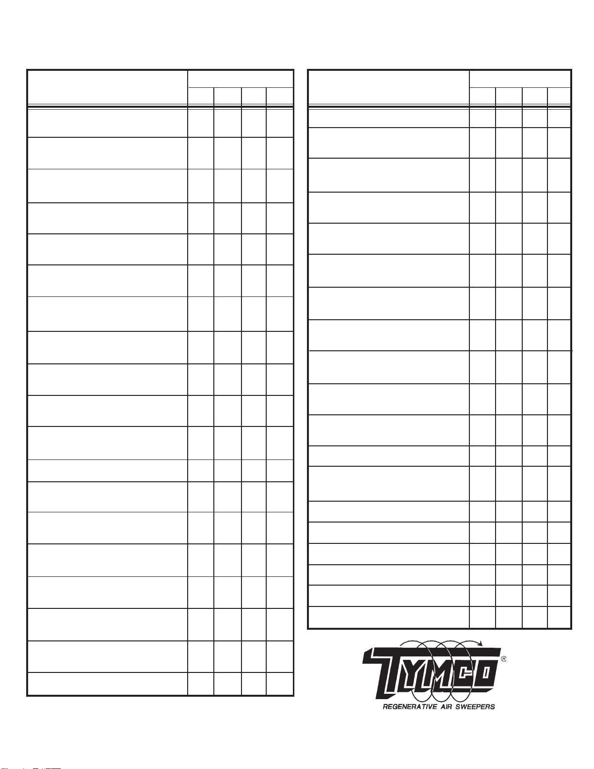
TYMCO REGENERATIVE AIR SWEEPER INSPECTION
AND REPETITIVE TASK SCHEDULE
600 500X 435 210
ADJUSTMENT OF GUTTER BROOM(S) A/R A/R A/R A/R
CLEANING OF GUTTER BROOM D D D D
TORQUE MOTOR SHAFT AREA
ROTATE PRESSURE AND SUCTION 75 75 75 75
HOSES 1/4 TURN HRS HRS HRS HRS
CHECK OF HYDRAULIC TANK D D D D
FLUID LEVEL
CHANGE OF HYDRAULIC 100 100 100 100
SYSTEM FILTER HRS HRS HRS HRS
TANK BREATHER FILTER N/A 100 N/A N/A
HRS
RETURN LINE FILTER - RESTRICTION N/A 100 N/A N/A
INDICATOR HRS
CHARGE LOOP FILTER - RESTRICTION N/A 100 N/A N/A
INDICATOR HRS
HYDRAULIC SYSTEM OIL CHANGE 1000 1000 1000 1000
NOTE: INITIAL CHANGE AT 100 HRS HRS HRS HRS HRS
CHANGE OF WATER PUMP OIL 150 150 150 150
(IF APPLICABLE) HRS HRS HRS HRS
CLEANING OF SPRAY NOZZLE TIPS A/R A/R A/R A/R
AND SCREENS
DRAIN WATER TANK D D D D
CLEANING OF HOPPER AND DUST D D D D
SEPARATOR CHAMBER
AUXILIARY ENGINE FLUID LEVEL CK. D D D D
WASHDOWN OF ENGINE RADIATOR(S) D D D D
FUNCTIONAL TEST SWEEPER LIGHTS D D D D
FUNCTIONAL TEST OF TRUCK BRAKES D D D D
FUNCTIONAL TEST OF TRUCK LIGHTS D D D D
MOUNT TRUCK FLUID LEVEL CHECK D D D D
PERFORM MODEL
600 500X 435 210
GUTTER BROOM(S) FOR IMPACT D D D D
DAMAGE/WEAR
PICK-UP HEAD BLAST ORIFICE FOR D D D D
LODGED FOREIGN MAT'L/ADJUSTMENT
PICK-UP HEAD TURNING VANES 100 100 100 100
FOR WEAR/FOREIGN MATERIAL HRS HRS HRS HRS
PICK-UP HEAD SKID PLATES FOR D D D D
WEAR AND IMPACT DAMAGE
PICK-UP HEAD CURTAINS FOR D D D D
WEAR/DAMAGE
PRESSURE AND SUCTION HOSES 100 100 100 100
FOR WEAR HRS HRS HRS HRS
HYDRAULIC SYSTEM FOR PLUMB- D D D D
ING OR COMPONENT LEAKAGE
WATER PUMP OIL LEVEL D D D D
(IF APPLICABLE)
WATER FILLER HOSE FILTER D D N/A N/A
SCREEN
WATER PUMP SUCTION HOSE D D D D
PRE-FILTER
ALL HOPPER AND TRANSITION D D D D
SEALS FOR WEAR/DAMAGE
HOPPER SCREEN FOR DAMAGE D D D D
DUST SEPARATOR LINER FOR D D N/A N/A
WEAR/DAMAGE
DUST SEPARATOR DOOR CLOSED D D N/A N/A
BEFORE OPERATING
BLOWER WHEEL FOR 100 100 100 100
WEAR/DAMAGE HRS HRS HRS HRS
ACCESSIBLE AREAS OF BLOWER 100 100 100 100
HOUSING LINER FOR WEAR/DAMAGE HRS HRS HRS HRS
BLOWER LIP FOR WEAR/DAMAGE 100 100 100 100
HRS HRS HRS HRS
ENGINE AIR INTAKE FILTER D D D D
RESTRICTION INDICATORS
MOUNT TRUCK TIRES D D D D
INSPECT MODEL
D = DAILY
HRS = HOURLY INTERVALS
A/R = AS REQUIRED

TABLE OF CONTENTS
TYMCO REGENERATIVE AIR SYSTEM .................................... 1
TYMCO SWEEPER Capabilities........................................... 1
Detailed Drawing....................................................... 3
Console Control Panel .................................................. 4
Light Indicator Module................................................... 5
Quick Reference Service Chart............................................ 6
Hopper Assembly ...................................................... 7
Blower Assembly ..................................................... 13
Hydraulic System ..................................................... 17
Gutter Broom ........................................................ 19
Pick-Up Head ........................................................ 23
Pressure Bleeder ..................................................... 33
Dust Control System ................................................... 34
Hand Hose Operation (Optional).......................................... 37
Auto Sweep Interrupt (ASI) (Optional) ..................................... 39
Sweeper Deluge (Optional).............................................. 40
Hydraulic Front Curtain Lifter (Optional) .................................... 42
Warranty ............................................................ 45


2008 1 500XOPTRS
THE TYMCO REGENERATIVE AIR SYSTEM
DESCRIPTION
The blower generates a constant blast of high velocity air that is directed down the pressure
side of the machine and into the pick-up head. Blast air travels across the pick-up head, picking
up normal debris and refuse in its path and sending it up the suction side of the machine.
At the same time that the blower is directing pressure down the pressure side, it is taking air
from inside the hopper, creating a suction; and consequently, it pulls debris up into the hopper.
The debris is deposited into the hopper while dusty air passes through the screen to a
multipass, centrifugal dust separator. The fines are then deposited back into the hopper
through the skimmer slot. Air, containing very fine dust, then moves into the blower and repeats
its cycle.
The unique REGENERATIVE AIR SWEEPER uses no restricting filters, resulting in more en-
ergy to do your work. Since the blower is used to push and pull, restriction due to clogging or
modification to any of the air passages will greatly affect the sweeper’s performance. In other
words, PRESSURE FOR THE BLAST depends on ample volume of air through the suction;
SUCTION depends on the discharge of air from the blast orifice.
Another point to consider is the fact that a very small air leak at the dump door, suction tube
seal, blower housing suction seal or suction hose will often cause a dusty condition. If the leak is
severe enough, air will have a slower velocity and performance will be lowered.
DO NOT ALLOW ANY AIR LEAKS.
CLEAN FRESH AIR DRAWN IN WILL BE DISCHARGED AS DUST.
TYMCO REGENERATIVE AIR SWEEPER CAPABILITIES
We at TYMCO honestly believe that government officials, contractors and all personnel directly
responsible for the performance and maintenance of equipment in their charge are concerned
with all phases of their operation.
Sweepers are one of the most controversial pieces of equipment with reference to operating
cost, performance, and maintenance. The general public does not realize the problems and de-
pends on people knowledgeable in this area. You, therefore, the person responsible for the
performance and maintenance of the sweeper should use your knowledge and experience to
achieve the results expected.
The TYMCO REGENERATIVE AIR SWEEPER can achieve your anticipated results while
keeping cost at a minimum. However, to realize the full potential of the TYMCO REGENERA-
TIVE AIR SWEEPER, YOU MUST UNDERSTAND ITS CAPABILITIES AND ADHERE
CLOSELY TO OPERATING AND JOB FUNCTIONS FOR WHICH IT WAS DESIGNED.
It is a fact that a licensed driver can operate this equipment; however, we strongly recommend
that the same driver operate it daily. It is proven that ability on the equipment is increased with
experience. We suggest that every operator thoroughly read and study the manual to make
sure that he/she understands its operation before ever attempting to operate the sweeper. It is
very important that every new operator be given this opportunity and that he does not rely solely
on methods of previous operators.

500XOPTRS 2 2008
A TYMCO REGENERATIVE AIR SWEEPER can be expected to clean normal debris that may
accumulate on streets, parking lots, and other flat paved surfaces. Using the machine for more
than it was originally designed will cause excessive wear and failure to achieve the desired
results.
This sweeper is not a Vacuum Cleaner. Cleaning is actually done by a stream of high velocity
air the full width of the pick-up head. A blower furnishes both pressure and suction. Air pressure
from the blower passes over the surface being swept within the pick-up head, blows up debris
in its path, and the suction pulls it into the hopper, where it is separated. Air continues on into the
blower and the cycle is repeated.
The TYMCO REGENERATIVE AIR SWEEPER is not intended nor is it expected to replace a
shovel crew or a front end loader. An inspection at the dump site, however, may reveal that
there are rocks and large objects in the hopper. This is due to air currents in the TYMCO RE-
GENERATIVE AIR SYSTEM having the potential to pick up various large objects and retain
them. The mixture of light debris will sometimes boost the large objects into the air stream and
carry them into the hopper. Objects such as cans, bottles, glass, paper, leaves and light stringy
refuse or normal daily accumulation of debris are easily picked up by the sweeper’s unique
REGENERATIVE AIR SYSTEM.
We can not say what blower RPM or truck speed at which you can achieve your sweeper’s full
capabilities because of the various types of sweeping encountered. However, blower RPM
should not exceed 2750. For parking lot sweeping consisting of paper, broken glass, cans,
leaves, etc., engine RPM can be reduced as desired. The sweeper can be operated at truck
speeds up to 10 MPH without changing blower RPM. The above limits are intended for smooth
wide open spaces that are sparsely scattered with debris. Slower truck speeds are advisable
for curb and gutter work or where there are many obstacles. This prevents damage and wear to
pick-up head and gutter broom. Faster speeds may be necessary under your particular condi-
tions. However, you may expect considerably more wear, not only by the hour as a result of
more coverage, but also by the mile. The heat generated at higher speeds will result in soften-
ing of the materials in contact with the surface. We would advise consideration of these facts
before allowing high speed operation, overloading and machine neglect.
SAVE FUEL, REDUCE NOISE, WEAR AND DUST.
OPERATE AT THE LOWEST POSSIBLE R.P.M. TO ADEQUATELY DO THE JOB.

2008 3 500XOPTRS

500XOPTRS 4 2008
CONTROL CONSOLE MODEL 500X
1. #10-24 Self Tap Screw (Not Shown)
2. Nut - 10/24 KEPT (Not Shown)
3. Switch Blank Cover
4. Key Switch (Not Shown)
5. Retainer - #12 (Not Shown)
6. Receptacle - #12 "J" Clip (Not Shown)
7. Switch Position Cover
8. Screw - Quick Opening - #12 (Not Shown)
9. Screw - M4-0.7x8PHPanHead
(Not Shown)
10. Switch Pack - PUH, Tilt, RH GB
11. Switch Pack - LH GB, Tilt RPM
12. Switch Pack - Lift, Tilt, Light
13. Switch Pack - Water, Aux, BAH
14. Switch Pack - HO, PUH, GB
15. Switch Pack - GB, Hopper, HO
16. Switch Pack - GB, Warn, WkLts
17. Switch Pack - RPM, LPB, GB Lt
18. Wiring Harness (Not Sown)
19. Multiplex Display
20. Control Panel
21. Jumper Harness, Short (Not Shown)
22. Jumper Harness, Long (Not Shown)
23. Light Indicator Module

2008 5 500XOPTRS
Switch Pack 1 Switch Pack 2
Switch Pack 3 Switch Pack 4
Switch Pack 5 Switch Pack 6
Switch Pack 7 Switch Pack 8
Post 2007 Light Indicator Module

500XOPTRS 6 2008
MODEL 500X
QUICK REFERENCE SERVICE CHART
(M01752)
ITEM DESCRIPTION RECOMMENDED SERVICE
1. Truck Engine Check oil level DAILY! Change oil and filter every 100
hours or every 3000 miles.
2. Truck Air Cleaner Inspect restriction indicator DAILY!
3. Water Tank Drain tank DAILY!
4. Industrial Engine Change oil and oil filter every 100 hours. Check oil level
DAILY!
5. Auxiliary Engine Air Cleaner Check restriction indicator DAILY!
6. Hyd. Tank Breather Filter Change every 500 hours.
7. Return Filter Check restriction indicator DAILY! Replace filter when
indicator reaches the yellow/red region.
8. Charger Loop Filter Check restriction indicator DAILY! Replace filter
when indicator reaches the yellow/red region.
9. Hydraulic Oil Check DAILY - Change out after first 100 hours; then every
1000 hours. (30 gallon tank) Use 10W hydraulic oil.
Refer to Sweeper Parts and Service Manual for list.
10. Separate Inlet Scroll Remove hopper screen and clean inlet every 500 hours.
11. Separator Door Open separator door and wash out chamber DAILY!
12. Hopper Screen Thoroughly wash screen DAILY! Never use sweeper with
large tears in screen.
13. Optional Hand Hose Check DAILY for holes and wear.
14. Sweeper Door Seals Inspect door seals DAILY! Hopper must be air tight.
Replace leaking or damaged seals.
15. Electric Water Pump Protect from freezing. No daily service necessary.
16. Truck Differential Follow manufacturers recommended service program.
17. Truck Tires Inspect each tire DAILY for flats.
18. Turning Vanes/Pick-up Head Inspect DAILY! Remove any material collected on vanes.
Replace as needed.
19. Pick-up Head Curtains Inspect DAILY! Replace as required.
20. Gutter Broom Check for bristle wear.
21. Truck Chassis Grease every 100 hours or every 3000 miles.
22. Scissor Lift Check track of any loose debris.
23. Blower Housing Seal Check DAILY for any tears.
24. Suction Transition Seal Check DAILY!
25. Suction Tube Check DAILY!
26. Dust Separator/Skimmer Slots Clean DAILY! Inspect skimmer slots weekly.
NEVER REACH INTO BLOWER HOUSING FOR ANY REASON !

2008 7 500XOPTRS
HOPPER ASSEMBLY
The TYMCO Model 500X hopper is one of the most important parts of the sweeper. Its function
is to separate and contain the heavy debris and fine particles from the air stream created by the
blower. In order for it to remain functioning, it must be cleaned DAILY! The Model 500X is a re-
generative air machine so the hopper must also remain air tight. The hopper also takes a lot of
abuse due to heavy, abrasive debris being shot into it at high speeds. It is important to read this
section thoroughly to understand all the hopper component functions.
Hopper and Lift Operation/Safety Interlocks
WARNING: ALWAYS CHECK FOR PEOPLE OR ANY OBSTRUCTIONS BE-
FORE OPENING HOPPER CHUTE AND DUMP DOOR.
Dump Door and Chute Operation
1. To open dump door and chute, engage the Hopper Tilt switch on the control panel to the
UP position. The chute will open first and then the dump door.
2. To close dump door and chute, engage the Hopper Tilt switch on the control panel to
the DOWN position. The dump door will close first and then chute.
WARNING: IF THE HOPPER IS LOADED, DON’T OPEN THE CHUTE AND
DUMP DOOR UNLESS YOU ARE READY TO COMPLETE THE
DUMP CYCLE. NEVER CLOSE THE DUMP DOOR AND CHUTE
WHEN DEBRIS STILL REMAINS ON CHUTE AND HOPPER FLOOR.
THE DUMP DOOR AND CHUTE COULD BE DAMAGED IF DEBRIS
PREVENTS THE DUMP DOOR FROM FULLY CLOSING.
WARNING: IF SWEEPING IN EXTREMELY WET AREAS, REMEMBER THAT
THE HOPPER COULD BE FULL OF WATER WHEN OPENING THE
DUMP DOOR. IN THIS SITUATION YOU SHOULD CRACK THE
DUMP DOOR OPEN INSTEAD OF FULLY OPENING IT. THIS AL-
LOWS THE WATER TO FLOW OUT OF THE HOPPER AND DOWN
THE CHUTE IN A CONTROLLED MANNER.
WARNING: Before working in this area, raise hopper and install the lift
assembly safety props. If unsure how to install safety props, SEE
SAFETY PROPS INSTALLATION PROCEDURE in the Lift Assem-
bly Section of this Operators Manual. Then remove ignition switch
key from sweeper control console and/or remove negative battery
lead terminal from battery. Serious and/or possible fatal injury can
result if these rules are not followed!
Hopper Lift and Tilt Operating Procedures
Sweeper Positioning
1. Position the chute side of the sweeper as close to the dump truck or container as
possible.

500XOPTRS 8 2008
2. Check where your stabilizers will be deploying. Make sure the area is clear of personnel
and obstructions such as a dump truck tire or a large rock where stabilizer foot contacts
the ground.
3. Pull up far enough so your chute will be positioned inside the perimeter of the dump
truck bed or container when tilted.
4. Folding the dump truck mirrors in can allow the sweeper to be positioned closer to the
dump truck
WARNING: Always check for people or any obstructions above you and be-
side you before lifting and tilting the hopper. Be extra careful not
to raise the hopper into power lines. Doing so could cause seri-
ous injury or even death.
WARNING: Always check your inclinometer on the dash before lifting or
tilting the hopper. Never lift or tilt the hopper if the sweeper is
inclined more than 5 degrees.
Hopper Lift Operation
1. Engage the Hopper Lift switch on the control panel to the UP position.
NOTE:The stabilizers will deploy first, and the STAB DOWN indicator light will turn
ON. The hopper will begin to lift after the stabilizers are fully extended.
2. Continue holding the Hopper Lift switch in the UP position.
NOTE:Once the MIN DUMP light illuminates the hopper is ready to tilt or it can be
taken to the maximum lift height.
3. Engage the Hopper Lift switch on the control panel to the DOWN position to lower the
hopper.
NOTE:The hopper will travel down below minimum dump height, the MIN DUMP light
will turn OFF, and the hopper will continue traveling down until it reaches the
bottom.
4. Continue holding the Hopper Lift switch in the DOWN position.
NOTE:The stabilizers will automatically retract.
5. Hold the Hopper Lift switch in the Down position until the STAB DOWN indicator light
turns OFF.
WARNING: If the hopper is loaded, don’t open the chute and dump door un-
less you are ready to complete the dump cycle. Never close the
dump door and chute when debris still remains on chute and hop-
per floor. The hydraulic cylinders could damage the dump door
and chute if debris prevents the dump door from fully closing.
WARNING: If sweeping in extremely wet areas, remember that the hopper
could be full of water when opening the dump door. In this situa-
tion you should crack the dump door open instead of fully open-
ing it. This allows the water to flow out of the hopper and down
the chute in a controlled manner.

2008 9 500XOPTRS
Hopper Tilt Operation
1. Follow steps 1 through 3 of the hopper lift operation.
2. Engage the Hopper Tilt Switch in the UP position.
NOTE:The chute will lower, and then the dump door will begin to open.
3. Continue holding the Hopper Tilt switch in the UP position.
NOTE:The CHUTE DOWN indicator light will turn ON. The hopper will begin to tilt
and the HOPPER TILTED indicator light will turn ON.
4. Continue holding the Hopper Tilt switch in the UP position until it is fully tilted.
NOTE:The hopper load will be distributed uniformly into the container from the far
side to the sweeper side as the hopper tilts.
NOTE: If the chute comes into contract with the dump truck or container, either
lift the hopper up or tilt it away from the obstruction.
5. Allow all of the debris in the hopper to fully unload.
6. Shake the hopper by lifting the hopper up and down in a fast, rhythmic motion.
NOTE:This will facilitate removing the debris that is still clinging to the inside of the
hopper.
7. Engage the Hopper Tilt Switch in the DOWN position.
NOTE:The hopper will tilt down, the dump door will close, and the chute will close.
8. Follow steps 3 through 5 of the hopper lift operation.
Safety Interlocks
1. The hopper will not lift or tilt when the blower is engaged (not in neutral).
2. The hopper will not lift or tilt when the truck transmission is not in neutral and the park
brake is not set.
3. If the stabilizers are down and/or the hopper is tilted, the warning buzzer and the corre-
sponding indicator light in the cab will alert the operator if:
a. The blower rpm switch is engaged.
b. The truck transmission is shifted out of neutral.
c. The park brake is released.
4. The hopper will not tilt below minimum dump height.
NOTE: If the hopper is tilted when lowering the lift, it will stop at minimum dump
height. The hopper can’t travel below minimum dump height until the hopper
is tilted down onto the lift (hopper tilted indicator light is OFF).

500XOPTRS 10 2008
Clean Out
At the end of the shift, drive the sweeper to a wash area. Wash out the hopper and make sure to
clean hopper screens, separator, hopper suction inlet, suction tube, and underneath the
pick-up head. An optional sweeper deluge is available to facilitate cleaning the hopper and un-
derneath the pick-up head.
Service
Aside from routinely washing out the hopper, the hopper assembly requires very little service.
1. Separator Assembly – The separator is a drum-like area found inside the blower side
of the hopper. Its function is to rid the air stream of dust particles through use of cen-
trifugal force rather than filters. Service the separator daily by fully tilting the hopper
to open separator door. Wash the interior of separator chamber.
2. Skimmer Slots – The skimmer slots allow the dust particles to escape the air stream
before it enters the blower housing. If they are clogged, then the separator WILL
NOT FUNCTION CORRECTLY. The dust particles in the air stream will continue
through the blower housing resulting in dust being blown out of the pick-up head.
This is why it is important to clean the separator DAILY.
3. Skimmer Hood – Inside the Model 500X hopper is a shielded area attached to the
separator door. This shielded area is formed by what is called the Skimmer Hood
and is designed to create a void into which the fine dust removed by the separator
skimmer slots can accumulate. The skimmer hood protects the separator skimmer
slots from being choked off by debris being deposited in the hopper during operation.
4. Separator Liner – The separator liner protects the separator wall from abrasion. This
is an item that is meant to be replaced over time and should be checked regularly.
5. Inlet Scroll and Separator Door Scrolls – The separator scrolls are wear items and
are meant to be replaced over time. They are lined with rubber and should be
checked regularly.
6. Sweeper Seals – The sweeper must maintain an air tight seal to perform adequately.
Inspect the dump door seal, blower housing seal, suction tube seal, and pressure
transition seal DAILY! If any of the seal material is missing, replace the seal. Refer to
the 500X Quick Reference Chart for seal locations.
7. Hopper Screens – The large screens found inside the hopper are very important for
preventing large debris from entering the separator and blower assembly. Inspect
the screens DAILY! If any large holes are found, do not operate the sweeper until
screen has been repaired or replaced. Refer to M01787 for hopper screen location.
Once every 500 hours the hopper screen should be removed and the inlet area
above the separator should be cleaned thoroughly. If allowed to become stopped up,
the sweeper efficiency would be drastically reduced. Refer to M01787 for the sepa-
rator inlet location.
8. Wear Liners – The suction inlet is one of the hoppers hot spots. It receives a lot of
debris impact because it is the first thing that the debris hits when entering the hop-
per. This is why the suction inlet is provided with two wear liners for protection.
These liners are meant to be replaced over time and should be checked DAILY for
wear. When a hole has been worn through them, it is time to replace them.
Table of contents
Other TYMCO Truck manuals
Popular Truck manuals by other brands

MAKINEX
MAKINEX JHT-U-2 Operator's manual

Still
Still ECU-25 Original instructions

Powerfix
Powerfix PMT 1.1 A1 translation of original operation manual

Still
Still HPT-20 Original instructions

freightliner
freightliner EconicSD operating instructions

Tractel Group
Tractel Group pioneer ST Operating and maintenance instructions