Tyro Musca User manual

Handleiding
Manual
Mode d’emploi
Bedienungsanleitung
Musca, Sedna
Aquarius


Publisher:
Tyro Remotes, 08/2016
Revision number:
4042.V1.3
Manufacturer: Tyro Remotes
Bedrijvenpark Twente 1b, 7602 KA Almelo
1
Inhoudsopgave NEDERLANDS
Talen
Pagina: 1 –6 Nederlands
7 –12 English
13 –18 Français
19 –24 Deutsch
Inhoud
Pagina: 1 1. Inleiding
2 2. Zender beschrijving Musca, standaard
3 3. Zender beschrijving Sedna, standaard
4 4. Montage
4 5. Bereikoptimalisatie
5 6. Programmeren van een (extra/gerepareerde) zender op de ontvanger
5 7. Ontvanger beschrijving & systeemspecificaties
6 8. Ontvanger aansluitschema
6 9. Verhelpen van storingen, service en reiniging
1. Inleiding
Woord vooraf
Deze handleiding is bedoeld voor de monteur en de eindgebruiker.
De bedieningsinstructie is afhankelijk van de toepassing, hiervoor is de eindverantwoordelijke verantwoordelijk.
Bewaar deze handleiding zorgvuldig en geef alle documenten mee, wanneer het product wordt verstrekt aan derden.
Doelmatig gebruik
Dit product is ontwikkeld voor de draadloze, radiografische aansturing van machines. Toepassingsvoorbeelden zijn: lieren, pompen, poorten,
deuren, verlichting, elektrische aansturingen en assenbesturing van trailers voor speciaal transport. Neem bij significant andere toepassingen
contact op met Tyro Remotes om verkeerd gebruik van het product te voorkomen.
Belangrijke informatie
Onze algemene verkoopvoorwaarden, op te vragen of te downloaden via de website (www.tyroremotes.nl), zijn ten allen tijde geldig. Na
installatie op uw systeem bent u verantwoordelijk voor de certificering van uw systeem in combinatie met de afstandsbediening.
Gebruiksomstandigheden
De handzender kan niet functioneren bij temperaturen onder de -20°C en boven 60°C. Voor optimaal gebruik wordt aanbevolen regelmatig de
batterij te vervangen.
Veiligheid
WAARSCHUWING: GEVAAR VOOR LETSEL OF MATERIËLE SCHADE!
Om gevaarlijke situaties te vermijden, neem altijd de volgende regels in acht:
Neem bij afwijking, onduidelijkheid of twijfel over onderstaande regels altijd contact op met Tyro Remotes.
Zichtverbinding: Alleen bedienen bij een zichtverbinding.
Beheer: Laat de handzender nooit onbeheerd achter.
Overbelasting: Altijd de werking simuleren na het aansluiten, alvorens de hoofdstroom te activeren, om schade te voorkomen.
ESD: Altijd de ESD richtlijnen opvolgen indien men in aanraking kan komen met interne delen, om schade te voorkomen.
Instructie: De eindgebruiker dient altijd door de verantwoordelijke van de te bedienen eenheid geïnstrueerd te worden over de veilige bediening
van de afstandsbediening in samenstelling met het geheel.
Bediening: Afgeraden wordt de handzender met (dikke)handschoenen te bedienen.
Levensduur: Bij goed onderhoud en normaal gebruik is de verwachte levensduur 10 jaar. Hierna wordt vervanging geadviseerd.
Meerdere zenders: Let op bij gebruik van meerdere zenders op één ontvanger. De ontvanger maakt standaard geen onderscheid tussen de
signalen van de verschillende zenders.
Bedrijfstemperatuur: De standaard veilige werkingstemperatuur ligt tussen -20°C. en 60°C.
Buiten bereik: Blijf als operator bij een actief systeem altijd binnen de reikwijdte (situatie afhankelijk) om risicovolle situaties te voorkomen.
WAARSCHUWING: BRANDGEVAAR EN LEVENSGEVAAR!
De batterij mag niet geopend of kortgesloten worden, deze kan oververhit raken of in brand vliegen.
Vermijd extreme omstandigheden en temperaturen die op de batterij in zouden kunnen werken, hierdoor kan de batterij
lekken en kunnen gevaarlijke stoffen vrijkomen.

Publisher:
Tyro Remotes, 08/2016
Revision number:
4042.V1.3
Manufacturer: Tyro Remotes
Bedrijvenpark Twente 1b, 7602 KA Almelo
2
2. Zender beschrijving Musca, standaard
Zender elementen
1. Zendindicator (groene LED)
LED knippert bij ieder verzonden signaal
Als de batterij bijna leeg is knippert deze LED langzamer
2. Batterij indicator (rode LED)
Als de batterij bijna leeg is knippert deze LED
3. Stopknop
Standaard passief uitgevoerd
Aangestuurd via puls, maakcontact
Kan ook worden gebruikt als de zender uit staat en de ontvanger aan
4. Functietoetsen
Met deze toetsen worden de functies bestuurd van het systeem
Kan als puls of als flip/flop (toetsvasthoudfunctie) worden uitgevoerd
5. ON-toets
2 seconden ingedrukt houden, zender actief en ontvanger actief
6. OFF-toets
Schakelt per direct de zender en ontvanger uit
Diverse uitvoeringen
1a. Musca 2F
2 functietoetsen
1 stopknop
1b. Musca 4F
4 functietoetsen
1 stopknop
1c. Musca 6F
6 functietoetsen
Geen stopknop
Geen batterij indicatie LED (batterij indicatie op zendindicator LED)
Horizontale toetsenblokkering
In de standaardconfiguratie kunnen de functietoetsen 1&2, 3&4, 5&6 niet tegelijkertijd gebruikt worden.
Batterij indicator
De nieuwe Musca zenders hebben 2 LED’s: één voor de signaalstatus en één batterij indicator LED. De batterij indicator LED knippert rood als
de batterij leeg dreigt te raken. Oudere Musca zenders hebben één LED. Deze gaat langzaam groen knipperen tijdens het zenden als de
batterij aan vervanging toe is.
Batterij vervangen van de Musca zenders
Draai de schroeven los aan de achterzijde van de zender en open voorzichtig de behuizing.
Vervang de batterij (9V blok batterij, Varta Alkaline) en sluit de behuizing.
Zorg ervoor dat de flat cable niet knikt, en let op dat u de schroeven niet te vast draait / doordraait.
Combineren van handzenders
De Sedna 2F en 4F en de Musca 2F en 4F kunnen met elkaar op 1 ontvanger worden gecombineerd. De Musca 6F kan niet worden
gecombineerd op 1 ontvanger met de hiervoor genoemde producten.
Figuur 1

Publisher:
Tyro Remotes, 08/2016
Revision number:
4042.V1.3
Manufacturer: Tyro Remotes
Bedrijvenpark Twente 1b, 7602 KA Almelo
3
3. Zender beschrijving Sedna, standaard
Zender elementen
1. Zendindicator (groene LED)
LED knippert bij ieder verzonden signaal
Als de batterij bijna leeg is knippert deze LED langzamer
2. Batterij indicator (rode LED)
Als de batterij bijna leeg is knippert deze LED
3. Stopknop
Standaard passief uitgevoerd
Aangestuurd via puls, maakcontact
Kan ook worden gebruikt als de zender uit staat en de ontvanger aan
4. Functietoetsen
Met deze toetsen worden de functies bestuurd van het systeem
Kan als puls of als flip/flop (toetsvasthoudfunctie) worden uitgevoerd
5. ON-toets
2 seconden ingedrukt houden, zender actief en ontvanger actief
6. OFF-toets
Schakelt per direct de zender en ontvanger uit
Diverse uitvoeringen
1a. Sedna 2F
2 functietoetsen
1 stopknop
1b. Sedna 4F
4 functietoetsen
1 stopknop
Horizontale toetsenblokkering
In de standaardconfiguratie kunnen de functietoetsen ▲&▼, ◄&► niet tegelijkertijd gebruikt worden.
Batterij indicator
De nieuwe Sedna zenders hebben 2 LED’s: één voor de signaalstatus en één batterij indicator LED. De batterij indicator LED knippert rood als
de batterij leeg dreigt te raken. Oudere Sedna zenders hebben één LED. Deze gaat langzaam groen knipperen tijdens het zenden als de batterij
aan vervanging toe is, deze bevindt zich tussen de functietoetsen.
Batterij vervangen van de Sedna zenders
Draai de schroeven los aan de achterzijde van de zender en open voorzichtig de behuizing.
Vervang de batterij (9V blok batterij, Varta Alkaline) en sluit de behuizing.
Zorg ervoor dat de flat cable niet knikt, en let op dat u de schroeven niet te vast draait / doordraait
Combineren van handzenders
De Sedna 2F en 4F en de Musca 2F en 4F kunnen met elkaar op 1 ontvanger worden gecombineerd. De Musca 6F kan niet worden
gecombineerd op 1 ontvanger met de hiervoor genoemde producten.
Figuur 2

Publisher:
Tyro Remotes, 08/2016
Revision number:
4042.V1.3
Manufacturer: Tyro Remotes
Bedrijvenpark Twente 1b, 7602 KA Almelo
4
4. Montage van een standaard systeem
De locatie van de ontvanger is van groot belang voor het bereik, houdt daarom rekening met de in hoofdstuk 5 beschreven punten.
Na aansluiten en montage dient u de werking van het systeem te testen, voordat de hoofdstroom ingeschakeld wordt.
LET OP: als u een klantspecifiek product hebt kan de
kabelaansluiting en montage afwijken. Lees altijd eerst
de klantspecifieke handleiding als deze is
meegeleverd!
LET OP: de Aquarius moet altijd na een hoofdzekering
van de voedingsbron worden aangesloten!
De standaard kabelaansluiting is als volgt:
Toets
Draadnummer
1
5
2
4
3
2
4
3
5 of Stoptoets
6
6
7
ON
-
OFF
-
Voeding 8-36 Vdc / V+
1
Massa / V-
Groen/geel
Input 1
8
Input 2
9
5. Bereikoptimalisatie
De locatie van de ontvanger is van groot belang voor het bereik, houdt daarom rekening met de onderstaande punten om het bereik van uw
systeem te optimaliseren:
- Plaats meerdere ontvangers minimaal 50cm uit elkaar
- Plaats de ontvanger of antenne nooit rechtstreeks tegen een metalen object, minimaal 50cm hier vandaan
- Monteer de ontvanger of antenne maximaal 3 á 4 meter boven het werkniveau; hoger of onder het werkniveau reduceert de reikwijdte
- Plaats de ontvanger minimaal 50cm uit de buurt van motoren of andere apparatuur welke een krachtveld kunnen genereren
- Plaats de ontvanger met antenne nooit in een schakelkast, cabine of vergelijkbare (metalen) behuizing
- Zorg ervoor, indien mogelijk, dat er een zichtverbinding is met de ontvanger tijdens het bedienen
- Bij toepassingen waarbij wordt gewerkt op gelijke hoogte zoals lieren of assensturing kan de ontvanger met antenne beter verticaal
gemonteerd worden
- Bij toepassingen met grote hoogte verschillen zoals lifttechniek kan de ontvanger met antenne beter horizontaal gemonteerd worden.
Reikwijdte
De maximaal aangegeven reikwijdte is altijd een indicatie gebaseerd op een meting met zichtverbinding zonder interferentie.
De reikwijdte kan niet worden gegarandeerd omdat deze altijd onderhevig is aan variabele omgevingsfactoren.
Met name afscherming, reflecties en schaduwwerking kunnen de reikwijdte beperken.
Voorwerpen die aanwezig zijn tussen de zender en de ontvanger, met name metalen en gewapend beton of absorberende objecten zoals
bomen, water of sneeuw, hebben een onvoorspelbare invloed op de reikwijdte.
In het algemeen geldt dat de reikwijdte optimaal is bij een zichtverbinding tussen de zender en de ontvanger.
Frequenties
Controleer of er geen draadloze apparatuur in de buurt van de ontvanger op dezelfde frequentie opereert, dit heeft een negatieve invloed op het
functioneren en de reikwijdte van het systeem.
Antenne montage
Zet de antenne op de BNC connector, druk de onderkant samen en draai deze rechtsom tot u de vergrendeling voelt klikken, trek aan de
antenne om te controleren of deze vast zit. De antenne kan nog wel draaien.
Figuur 3

Publisher:
Tyro Remotes, 08/2016
Revision number:
4042.V1.3
Manufacturer: Tyro Remotes
Bedrijvenpark Twente 1b, 7602 KA Almelo
5
6. Programmeren van een (extra/gerepareerde) zender op de ontvanger
LET OP: Alle systemen zijn af fabriek reeds geprogrammeerd. Tenzij u een
extra/gerepareerde handzender wilt programmeren op de ontvanger, anders kunt u dit
deel overslaan!
Indien u een extra of nieuwe handzender op de Aquarius ontvanger wilt programmeren, ga dan als volgt te werk:
Stap
Omschrijving
1.
Zorg dat de Aquarius correct is aangesloten en voorzien is van voedingsspanning
2.
Druk 1 seconde op de zwarte programmeerknop onder op de ontvanger, de status LED op de ontvanger licht
rood op
3.
Zet de handzender aan, de LED op de ontvanger gaat nu geel knipperen
4.
De zender is geprogrammeerd op de ontvanger
5.
Controleer de werking door op een knop te drukken, als op de ontvanger de status LED geel knippert
(± 2x per seconde), is het programmeren succesvol
Om alle zenders uit het geheugen van de ontvanger te wissen, houdt u de programmeerknop langer dan 8 seconden ingedrukt totdat de rode
status LED op de Aquarius ontvanger uitgaat.
7. Aquarius ontvanger beschrijving & systeemspecificaties
1. Antenne
Standaard bevat dit product een flexibele antenne
Het product is ook uitvoerbaar met een BNC connector waar een BNC antenne en of een verlengkabel op gemonteerd kan
worden.
2. Status LED
Dit is een duo LED; deze kan rood of geel oplichten
Rood constant brandend: de ontvanger staat in programmeermodus
Geel snel knipperend: ± 10x per seconde, de ontvanger ontvangt een signaal van een niet geprogrammeerde zender
Geel langzaam knipperend: ± 2x per seconde, de ontvanger ontvangt pakketten van een geprogrammeerde handzender
3. Zekering houder
Deze dop kan eruit gedraaid worden met een platte schroevendraaier, inbus 8 of steeksleutel 19
Achter de dop zit een andere dop welke met een platte schroevendraaier een kwartslag naar links gedraaid kan worden
De zekering houder kan er uit worden gehaald en de 10A snel glaszekering (5 x 20 mm) kan worden vervangen
4. Kabel
Deze 10-aderige kabel wordt gebruikt om de ontvanger aan te sluiten
5. Programmeer toets
Als deze 1 seconde wordt ingedrukt gaat de ontvanger in programmeermodus
Als deze langer dan 8 seconden wordt ingehouden worden alle geprogrammeerde zenders gewist uit het geheugen
Ontvanger specificaties
Voedingsspanning / Schakelspanning
8 –36 Vdc
Stroomverbruik
15 mA
Maximale belasting
4 A per uitgang
IP beschermingsgraad
IP68
Zenders per ontvanger
Max. 54
Zender specificaties
Batterij
1x 9V blokbatterij 600 mAh
Stroomverbruik standby
2 µA
Stroomverbruik zenden
5 mA
Gebruiksduur batterij, bij normaal gebruik
2 jaar
IP beschermingsgraad
IP65
Figuur 4

Publisher:
Tyro Remotes, 08/2016
Revision number:
4042.V1.3
Manufacturer: Tyro Remotes
Bedrijvenpark Twente 1b, 7602 KA Almelo
6
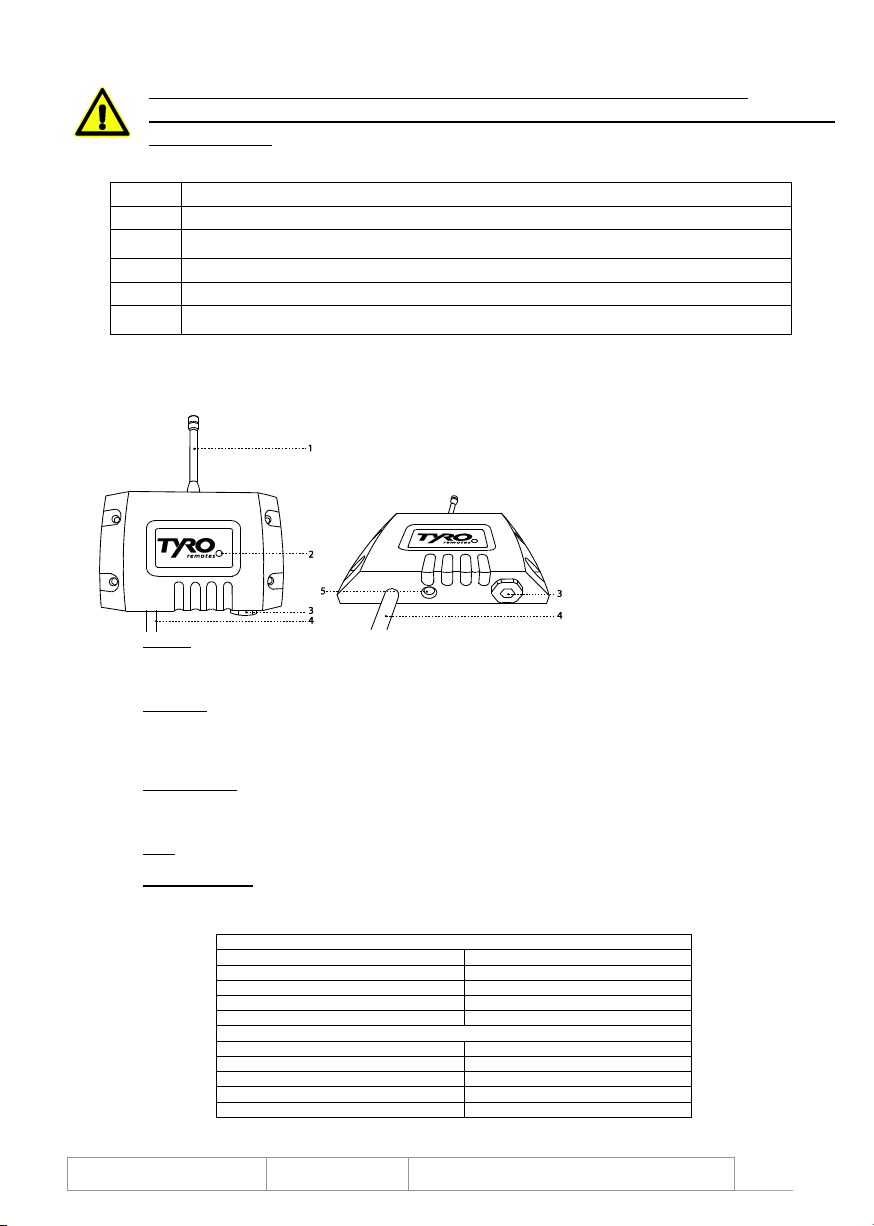
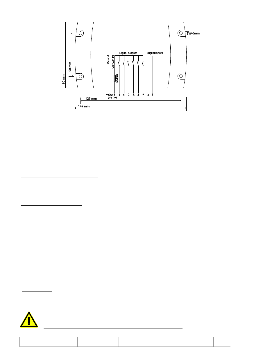
8. Aquarius ontvanger aansluitschema
9. Verhelpen van storingen
Wanneer de apparatuur niet naar behoren werkt controleer de volgende punten:
De ontvanger reageert niet als u een commando geeft op de zender
De ontvanger heeft geen voedingsspanning
Controleer of de ontvanger juist is aangesloten en of de zekering intact is
U staat buiten het bereik van de ontvanger
Zorg ervoor dat u binnen het bereik van de ontvanger bent en dat er geen grote (metalen) objecten tussen u en de ontvanger, of
de antenne van de ontvanger staan
Indien nodig kan met een antenne verlengkabel de antenne op een andere plek worden gemonteerd
De zender is niet geprogrammeerd op de ontvanger
Volg de stappen in hoofdstuk 6 om opnieuw de zender op de ontvanger te programmeren
De zender functioneert niet
De zender gaat niet aan als u de ON-toets indrukt.
De batterij kan leeg zijn, vervang de batterij
Is dit niet het geval, dan is de zender defect en dient u het systeem aan te bieden ter reparatie
Het bereik is te klein
De antenne is niet goed gemonteerd op de ontvanger.
Zie de richtlijnen in hoofdstuk 5, Antenne montage
De antenne is niet goed gepositioneerd.
Zie de richtlijnen in hoofdstuk 5
Service
Als een Tyro Remotes afstandsbesturing een mankement vertoont of onderhoud nodig heeft, dan dient u het gehele systeem (zender én
ontvanger) naar Tyro Remotes te sturen ter reparatie. Voor een vlotte afhandeling vragen wij u om het serviceformulier uit te printen, in te vullen
en met het systeem mee te sturen. Het service formulier kunt u downloaden op www.tyroremotes.nl/support/reparaties-en-onderdelen. Mochten
er hoge kosten verbonden zijn aan de reparatie, dan wordt dit altijd van te voren aan u gemeld.
Reinigen en onderhoud
Gebruik geen chemische reinigers of schuurmiddelen voor de reiniging, hierdoor kan het bedieningspaneel worden aangetast
Aangeraden wordt een vochtige doek met een lichte zeepsop te gebruiken
Bij hardnekkige verontreiniging kunt u contact opnemen met Tyro Remotes, hoe het beste de verontreiniging te reinigen
Dompel het apparaat nooit onder in water of andere vloeistoffen, in dit geval kan het apparaat defect raken
Waarborg dat geen water in het apparaat dringt, als dit toch gebeurd, gebruikt u het apparaat pas weer wanneer het volledig
gedroogd en getest is
Verkoopvoorwaarden en certificering
Alle leveringen geschieden volgens de algemene verkoopvoorwaarden. Deze kunt u bij ons opvragen, of downloaden op de website
(www.tyroremotes.nl). De producten van Tyro Remotes zijn voor vele toepassingen gecertificeerd. Deze certificaten kunt u bij ons opvragen. U
dient bij de montage op uw eigen systeem rekening te houden met de voor uw toepassing geldende machinerichtlijnen. Indien u uw machine
standaard met een Tyro afstandsbediening uitrust, is de certificering van het gehele systeem - inclusief afstandsbediening - uw
verantwoordelijkheid.
LET OP: Voor mogelijke persoonlijke, materiële en gevolgschade door ondeskundig of
nonchalant gebruik van dit product, wat in strijd is met de in deze handleiding opgenomen
bepalingen en aanwijzingen, is Tyro Remotes niet verantwoordelijk.
Figuur 5

Publisher:
Tyro Remotes, 08/2016
Revision number:
4042.V1.3
Manufacturer: Tyro Remotes
Bedrijvenpark Twente 1b, 7602 KA Almelo
7
Contents ENGLISH
Languages
Page: 1 –6 Nederlands
7 –12 English
13 –18 Français
19 –24 Deutsch
Contents
Page: 7 1. Introduction
8 2. Description of a Musca transmitter, standard
9 3. Description of a Sedna transmitter, standard
10 4. Assembly of a standard system
10 5. Range optimisation
11 6. Programming (an additional or repaired) transmitter to the receiver
11 7. Receiver description & system specifications
12 8. Receiver connection diagram
12 9. Resolving problems, service and cleaning
1. Introduction
Foreword
This manual is intended for both the installer and the user.
The operating instructions depend on the application; the person installing the system is ultimately responsible for this.
Keep this manual, if you pass the product on to third parties, provide them with all the documents.
Intended use
This product was designed for the wireless, radiographic control of machines by means of mosfets. Examples of applications include winches,
pumps, gates, doors, lighting, electric controls and axle control of trailers for special transport. If your application differs significantly, please
contact Tyro Remotes to avoid incorrect use of this product.
Important information
Our general terms and conditions of sale that can be requested or downloaded via our website (www.tyroremotes.com) apply at all times. After
installing into your system, you are responsible for having the system as a whole in combination with the remote control certified.
Operating conditions
The hand-held transmitter cannot operate at temperatures under -20°C and above 60°C. For optimum use we recommend regularly changing
the battery.
Safety
WARNING: RISK OF INJURY OR DAMAGE!
To avoid dangerous situations, please observe the following rules:
In case of changes, doubts about the rules or if something is unclear, please contact Tyro Remotes.
Line of sight: Use only if there is a line of sight.
Care: Never leave the hand-held transmitter unattended.
Overload: Always simulate operation on connection before connecting to the mains to avoid any damage.
ESD: Always follow the ESD instructions if you come into contact with internal parts to avoid any damage.
Instruction: The end user must always be instructed on the safe operation of the remote control in combination with the entire system by the
person responsible for the system.
Operation: Using the hand-held transmitter with (thick) gloves is not recommended.
Life: If the remote is well maintained and used normally, the expected life is 10 years. After that we recommend replacing the remote.
Multiple transmitters: Please pay attention when using multiple transmitters with one receiver. In the standard configuration the receiver does
not distinguish between the signals of the different transmitters.
Operating temperature: The standard, safe operating temperature is between -20°C and 60°C.
Out of range: The operator of an active system should always remain in range (varies depending on the situation) to avoid risky situations.
WARNING: RISK OF FIRE AND DEATH!
The battery may not be opened or short-circuited, it can overheat or catch fire.
Avoid extreme conditions and temperatures that could affect the battery, causing it to leak and release harmful
substances.

Publisher:
Tyro Remotes, 08/2016
Revision number:
4042.V1.3
Manufacturer: Tyro Remotes
Bedrijvenpark Twente 1b, 7602 KA Almelo
8
2. Description of a Musca transmitter, standard
Transmitter elements
1. Transmission indicator (green LED)
LED flashes for each signal transmitted
When the battery is almost empty, the LED flashes more slowly
2. Battery indicator (red LED)
This LED flashes when the battery is almost empty
3. Stop button
Standard passive version
Controlled by pulse, normally open
Can also be used if the transmitter is switched off and the receiver is on
4. Function keys
These keys control the functions of the system
Can be executed as pulse or flip/flop (key hold-down function)
5. ON-button
Keep pressed down for 2 seconds, to activate the transmitter and the receiver
6. OFF-button
Immediately switches off the transmitter and the receiver
Different versions
1a. Musca 2F
2 function keys
1 stop button
1b. Musca 4F
4 function keys
1 stop button
1c. Musca 6F
6 function keys
No stop button
No battery indicator LED (battery indication on transmission indicator LED)
Horizontal key block
In the standard configuration the function keys 1&2, 3&4, 5&6 are horizontally blocked so that only one of each pair can be used at a time.
Battery indicator
The new Musca transmitters have 2 LEDs: one for the signal status and one battery indicator LED. The battery indicator LED flashes red when
the battery is almost empty. Older Musca transmitters have only one LED. It flashes green more slowly during transmission when the battery
needs changing.
Replacing the battery of the Musca transmitters
Loosen the screws on the back of the transmitter and carefully open the casing.
Replace the battery (9V block battery, Varta Alkaline) and close the casing.
Make sure that the flat cable is does not kink and that you do not over tighten the screws.
Combining hand-held transmitters
The Sedna 2F and 4F and the Musca 2F and 4F can be combined with each other on one receiver. The Musca 6F cannot be used with the
aforementioned products on one receiver.
Figure 1

Publisher:
Tyro Remotes, 08/2016
Revision number:
4042.V1.3
Manufacturer: Tyro Remotes
Bedrijvenpark Twente 1b, 7602 KA Almelo
9
3. Description of a Sedna transmitter, standard
Transmitter elements
1. Transmission indicator (green LED)
LED flashes for every signal sent
This LED flashes more slowly when the battery is almost empty
2. Battery indicator (red LED)
This LED flashes when the battery is almost empty
3. Stop button
Standard passive version
Controlled by pulse, normally open
Can also be used if the transmitter is off and the receiver is on
4. Function keys
These keys control the functions of the system
Can be executed as pulse or flip/flop (key hold-down function)
5. ON-button
Keep pressed down for 2 seconds, transmitter active and receiver active
6. OFF-button
Immediately switches off the transmitter and receiver
Different versions
1a. Sedna 2F
2 function keys
1 stop button
1b. Sedna 4F
4 function keys
1 stop button
Horizontal key block
In the standard configuration the function keys ▲&▼, ◄&► are blocked so that only one of each pair can be used at a time.
Battery indicator
The new Sedna transmitters have 2 LEDs: one for the signal status and one battery indicator LED. The battery indicator LED flashes red when
the battery is almost empty. Older Sedna transmitters have only one LED. It flashes green more slowly during transmission when the battery
needs changing, it is between the function keys.
Replacing the battery of the Sedna transmitters
Loosen the screws on the back of the transmitter and carefully open the casing.
Replace the battery (9V block battery, Varta Alkaline) and close the casing.
Make sure that the flat cable is does not kink and that you do not over tighten the screws.
Combining hand-held transmitters
The Sedna 2F and 4F and the Musca 2F and 4F can be combined with each other on one receiver. The Musca 6F cannot be used with the
aforementioned products on one receiver.
Figure 2

Publisher:
Tyro Remotes, 08/2016
Revision number:
4042.V1.3
Manufacturer: Tyro Remotes
Bedrijvenpark Twente 1b, 7602 KA Almelo
10
4. Assembly of a standard system
For the range to be optimal the location of the receiver is of great importance, there for take chapter 5 in account.
After connection and assembly the system must be tested before switching on the mains.
PLEASE NOTE: if you have a customised product, the cable connection and assembly may
differ. Please always read your specific manual first!
PLEASE NOTE: the Aquarius must always be connected
to the power source behind a main fuse!
The standard cable connection is as follows:
Key
Wire number
1
5
2
4
3
2
4
3
5 or Stop button
6
6
7
ON
-
OFF
-
Power supply 8-36 Vdc / V+
1
Common / V-
Green/yellow
Input 1
8
Input 2
9
5. Range optimisation
The location of the receiver is of great influence on the maximum range, there for take in
account the following points in order to optimize the range of the system:
- Place several receivers at least 50cm apart
- Never directly place the receiver or antenna on metal objects but at least 50 cm away
- Mount the receiver or antenna approximately 3 to 4 metres above work height, higher or
under work height reduces range significantly
- Place the receiver or antenna at least 50 cm away from engines or other devices that can generate a force field
- Never place the receiver with antenna in the cabin of a vehicle, a switchbox, or a similar (metal) casing
- If the receiver needs to be placed in an unfavourable location, the antenna can be placed elsewhere using an antenna extension cord
- If possible try to maintain a line of sight with the receiver during operation
Range
The maximum range indicated is based on a measurement with line of sight without interference
The indicated range cannot be guaranteed because it is always subjective to variable environmental factors
In particular deflection, reflection and shadows can decrease the maximum range
Objects present in between the transmitter and receiver, in particular metals, reinforced concrete or absorbing objects like trees or snow, have
an unpredictable influence on the maximum range
In general the optimal range can be achieved when there is a line of sight between the transmitter and the receiver
Frequencies
Check if there are no other wireless devices that operate on the same frequency, this will have a negative impact on the performance and range
of the system.
Antenna installation
Put the antenna on the BNC connector on top of the receiver, squeeze the bottom side of the antenna together and turn clockwise until you feel
it lock in place. Pull lightly on the antenna to check if it is secure. The antenna is still able to turn around.
Figure 3

Publisher:
Tyro Remotes, 08/2016
Revision number:
4042.V1.3
Manufacturer: Tyro Remotes
Bedrijvenpark Twente 1b, 7602 KA Almelo
11
6. Programming (an additional or repaired) transmitter to the receiver
PLEASE NOTE: all systems have already been programmed at the factory! You can skip this
part unless you wish to program an additional or repaired hand-held transmitter to the receiver!
If you wish to program an additional or new hand-held transmitter to the Aquarius receiver, take the following steps:
Step
Description
1.
Make sure that the Aquarius is correctly connected and has supply voltage.
2.
Press the black programming button on the bottom of the receiver for 1 second, the status LED on the receiver will light
up red.
3.
Switch on the hand-held transmitter, the LED on the receiver will now flash yellow.
4.
The transmitter is now programmed to the receiver.
5.
Make sure it works by pressing a button, if the status LED on the receiver flashes yellow (± 2x per second), the
programming was successful.
To delete all the transmitters from the memory of the receiver, keep the programming button pressed down for longer than 8 seconds until the
red status LED on the Aquarius switches off.
7. Description of Aquarius receiver & system specifications
1. Aerial
This product comes standard with a flexible aerial
The product is also available with a BNC connector to which a BNC aerial or an extension cable can be connected
2. Status LED
This is a double LED that can light up red or yellow
Red constantly on: the receiver is in programming mode
Yellow flashing quickly (± 10x per second): the receiver is receiving a signal from a non-programmed transmitter
Yellow flashing slowly (± 2x per second): the receiver is receiving packets from a programmed hand-held transmitter
3. Fuse holder
This cap can be removed using a flat screwdriver, Allen key no. 8 or open-end wrench no. 19
Behind the cap there is another cap that can be turned 90° anticlockwise using a flat screwdriver
The fuse holder can now be removed and the 10A quickblow glass fuse (5 x 20mm) can be changed
4. Cable
This 10-core cable is used to connect the receiver
5. Programming key
If this is pressed down for 1 second, the receiver goes into programming mode
If it is kept pressed down for longer than 8 seconds, all the programmed transmitters will be deleted from the receiver’s memory
Receiver specifications
Powersupply / switching voltage
8 –36 Vdc
Power usage
15 mA
Maximum load
4 A per output
IP classification
IP68
Transmitters per receiver
Max. 54
Transmitter specifications
Battery
1x 9V block 600 mAh (Varta Alkaline)
Power usage standby
2 µA
Power usage during transmission
5 mA
Battery life with normal use
2 years
IP classification
IP65
Figure 4

Publisher:
Tyro Remotes, 08/2016
Revision number:
4042.V1.3
Manufacturer: Tyro Remotes
Bedrijvenpark Twente 1b, 7602 KA Almelo
12
8. Aquarius receiver connection diagram
9. Resolving problems
If the equipment is not working properly, check the following points:
The receiver does not react when you give a command on the transmitter
The receiver does not have any power
Make sure the receiver is connected correctly and the fuse is intact
You are out of range of the receiver
Make sure you are within range of the receiver and there are no large (metal) objects between you and the receiver or aerial of the
receiver
If necessary, the antenna can be installed in another place with the aid of an antenna extension cable.
The transmitter is not programmed to the receiver
Follow the steps in section 5 to program the transmitter to the receiver
The transmitter does not work
The transmitter does not switch on if you press the ON-button
The battery may be empty; change the battery
If this is not the solution, then the transmitter maybe defective and you should offer the system for repairs
The range is too small
The antenna is not properly installed on top of the receiver.
See guidelines provided in chapter 5, antenna installation
The antenna has not been positioned correctly.
See guidelines provided in chapter 5
Service
If a Tyro Remotes remote control has a problem or requires service, please send the entire system (transmitter and receiver) to Tyro Remotes
for repairs. To ensure that this occurs smoothly, please print out the service form, fill it in and send it to us together with the system. The service
form can be downloaded from www.tyroremotes.com/support/repairs. If the repairs are not free, we will always inform you of this in advance.
Cleaning and maintenance
Do not use chemical cleaning agents or abrasives to clean the device
They can affect the operating panel
We recommend using a damp cloth and slightly soapy water
If the device becomes very dirty, please contact Tyro Remotes to consult on how to best clean it
Never submerge the device in water or other liquids. If you do so it could damage the device
Make sure that no water gets into the device. If it does, do not use the device until it has completely dried out and has been tested
Conditions of sale and certification
All deliveries are made according to our conditions of sale. These are available upon request or can be downloaded directly from our website
(www.tyroremotes.com). The products are certified for many applications. These certificates are also available upon request. You yourself are
responsible for keeping in account which machine directive guidelines apply for your situation. When you outfit you’re machine by default with a
Tyro remote control, the certification of the machine as a whole –including remote controle system –is your responsibility.
PLEASE NOTE: Tyro Remotes is not responsible for personal, material and consequential
damages caused by improper or careless use, which are in conflict with the provisions,
instructions and guidelines included in this manual
Figure 5

Publisher:
Tyro Remotes, 08/2016
Revision number:
4042.V1.3
Manufacturer: Tyro Remotes
Bedrijvenpark Twente 1b, 7602 KA Almelo
13
Sommaire FRANÇAIS
Langues
Page : 1 –6 Nederlands
7 –12 English
13 –18 Français
19 –24 Deutsch
Contenu
Page : 13 1. Introduction
14 2. Description de la télécommande Musca, standard
15 3. Description de la télécommande Sedna, standard
16 4. Installation
16 5. L´optimisation de la porte
17 6. Programmation d’une télécommande (supplémentaire/réparée) au récepteur
17 7. Description du récepteur & spécifications du système
18 8. Schéma de connexion du récepteur
18 9. Dépannage, entretien et nettoyage
1. Introduction
Préambule
Le présent mode d’emploi est destiné tant au monteur qu’à l’utilisateur final.
Les instructions pouvant varier en fonction de l’application, la responsabilité incombe au responsable final.
Conservez ce mode d’emploi soigneusement et joignez-le au produit si ce dernier est remis à des tiers.
Utilisation appropriée
Le produit a été développé pour la commande à distance sans fil de machines à l’aide d’ondes radio. Quelques exemples d’application : treuils,
pompes, portails, portes, éclairage, systèmes de commande électrique et pilotage des essieux des remorques lors des transports
exceptionnels. Contactez Tyro Remotes au cas où vous envisagez des applications significativement différentes afin d’éviter une utilisation
inappropriée.
Information importante
Tout nos produits sont soumis à nos conditions de ventes. Nos conditions générales de vente sont disponibles à la consultation et au
téléchargement sur le site internet www.tyroremotes.fr. L’installation du produit sur votre système engage votre responsabilité pour la
certification de l’ensemble de l’installation : votre système avec la télécommande.
Environnement d’utilisation
La télécommande ne fonctionne pas avec des températures inférieures à -20°C et supérieures à 60°C. Le remplacement régulier de la pile est
conseillé afin de garantir un fonctionnement optimal.
Sécurité
ATTENTION : RISQUES DE BLESSURES ET DE DEGATS MATERIELS
Toujours respecter les recommandations suivantes afin d’éviter les situations dangereuses :
Contactez Tyro Remotes sans hésiter en cas d’inconsistance, de confusion ou de doute par rapport aux
recommandations ci-dessous :
Contact visuel : Gardez toujours un contact visuel sur l’objet commandé pendant l’utilisation de la télécommande.
Présence : Ne laissez jamais la télécommande à un endroit sans surveillance.
Surcharge : Afin d’éviter tout risque de dégâts, effectuez une simulation du fonctionnement après chaque connexion et avant d’activer le
courant principal.
ESD : Si vous entrer en contact avec les parties internes, toujours suivre les directives ESD pour éviter tout risque de dommage.
Instructions : Le responsable du système de commande est chargé de fournir à l’utilisateur final, les instructions d’utilisation concernant la
sécurité et le fonctionnement de la télécommande et de l’ensemble.
Utilisation : Il est déconseillé de porter des gants (épais) pendant l’utilisation de la télécommande.
Durée de vie : Lors d’une utilisation normale et d’un bon entretien du matériel, la durée de vie est estimée à 10 ans. Après ce délai, nous
conseillons de remplacer le matériel.
Plusieurs télécommandes : Soyez prudent lors de l’utilisation de plusieurs télécommandes avec un seul récepteur. Le récepteur ne différencie
pas par défaut les signaux provenant des différentes télécommandes.
Résistance à la température : Le fonctionnement est garanti avec des températures comprises entre -20°C et 60°C.
Portée : Pour éviter toutes situations à risque, l’opérateur doit rester à l’intérieur du champ de portée (en fonction de la situation) lorsque le
système de commande est actif.
ATTENTION : RISQUE D’INCENDIE ET DANGER DE MORT !
La batterie peut surchauffer ou s’enflammer en cas d’ouverture ou de court-circuit. Evitez les conditions extrêmes et
les températures pouvant entraîner le surchauffe de la batterie et donc des fuites de substances dangereuses.

Publisher:
Tyro Remotes, 08/2016
Revision number:
4042.V1.3
Manufacturer: Tyro Remotes
Bedrijvenpark Twente 1b, 7602 KA Almelo
14
2. Description de la télécommande Musca, standard
Composants de la télécommande
1. Indicateur d’émission (LED verte)
La LED clignote à chaque signal envoyé
La LED clignote plus lentement lorsque la pile est faible
2. Indicateur de pile faible (LED rouge)
Cette LED clignote lorsque la pile est faible
3. Bouton STOP
Passif par défaut
Actif par impulsion, contact à fermeture
Fonctionne également lorsque la télécommande est éteinte et que le
récepteur est allumé
4. Touches de fonction
Ces touches contrôlent les fonctions du système
Disponible en impulsion ou bistable (touches à auto-maintien)
5. Touche ON
Appuyez pendant 2 secondes pour allumer la télécommande et le récepteur
6. Touche OFF
Éteint immédiatement la télécommande et le récepteur
Différentes versions
1a. Musca 2F
2 touches de fonction
1 bouton STOP
1b. Musca 4F
4 touches de fonction
1 bouton STOP
1c. Musca 6F
6 touches de fonction
Pas de bouton STOP
Pas d’indicateur de pile LED (indicateur de pile faible via la LED d’émission)
Blocage horizontal des touches
Dans la configuration par défaut, les paires de touches situées côte à côte, c’est-à-dire 1 et 2, 3 et 4, 5 et 6, bloquent l’activation l’une de l’autre.
Par exemple, on ne peut pas activer les touches 1 et 2 simultanément.
Indicateur de pile faible
Les nouvelles télécommandes Musca disposent de 2 voyants LED : le premier indique l’émission d’un signal, le second clignote en rouge
lorsque la pile est faible. Les modèles Musca plus anciens ne disposent que d’un seul voyant LED, qui clignote plus lentement lors de l‘émission
du signal lorsqu’il faut changer la pile.
Remplacement de la pile des télécommandes Musca
Dévissez les vis au dos de la télécommande et ouvrez le boîtier avec précaution.
Remplacez la pile (rectangulaire de 9V, Varta Alkaline) et refermez le boîtier.
Faites attention à ne pas déformer le câble plat ni à trop serrer les vis.
Combiner les télécommandes
Les télécommandes Sedna 2F et 4F et Musca 2F et 4F peuvent être programmées à un seul et même récepteur. Cela n’est pas possible avec
la télécommande Musca 6F, elle ne peut pas fonctionner avec les autres télécommandes mentionnées ci-dessus avec un seul et même
récepteur.
Image 1

Publisher:
Tyro Remotes, 08/2016
Revision number:
4042.V1.3
Manufacturer: Tyro Remotes
Bedrijvenpark Twente 1b, 7602 KA Almelo
15
3. Description de la télécommande Sedna, standard
Composants de la télécommande
1. Indicateur d’émission (LED verte)
La LED clignote à chaque signal envoyé
La LED clignote plus lentement lorsque la pile est faible
2. Indicateur de la pile (LED rouge)
Cette LED clignote lorsque la pile est faible
3. Bouton STOP
Passif par défaut
Activé par impulsion, contact à fermeture
Fonctionne également lorsque la télécommande est éteinte et
que le récepteur est allumé
4. Touches de fonction
Ces touches commandent les fonctions du système
Disponible en impulsion ou bistable (touches à auto-maintien)
5. Touche ON
Appuyez pendant 2 secondes pour allumer l’émetteur et le récepteur
6. Touche OFF
Éteint immédiatement l’émetteur et le récepteur
Différentes versions
1a. Sedna 2F
2 touches de fonction
1 bouton STOP
1b. Sedna 4F
4 touches de fonction
1 bouton STOP
Blocage des touches
Dans la configuration par défaut, les paires de touches ▲ & ▼ et ◄ & ► ne peuvent pas être activées simultanément.
Indicateur de la pile
Les nouvelles télécommandes Sedna disposent de 2 voyants LED : le premier indique l’émission d’un signal, la second clignote en rouge
lorsque la pile est faible. Les modèles Sedna plus anciens ne disposent que d’un seul voyant LED, qui clignote plus lentement lors de l‘émission
de signaux lorsqu’il faut changer la pile.
Remplacement de la batterie des télécommandes Sedna
Dévissez les vis au dos de la télécommande et ouvrez le boîtier avec précaution.
Remplacez la pile (rectangulaire de 9V, Varta Alkaline) et refermez le boîtier.
Faites attention à ne pas déformer le câble plat ni à trop serrer les vis.
Combiner les télécommandes
Les télécommandes Sedna 2F et 4F et Musca 2F et 4F peuvent être programmées à un seul et même récepteur. Cela n’est pas possible avec
la télécommande Musca 6F, elle ne peut pas fonctionner avec les autres télécommandes mentionnées ci-dessus avec un seul et même
récepteur.
Image 2

Publisher:
Tyro Remotes, 08/2016
Revision number:
4042.V1.3
Manufacturer: Tyro Remotes
Bedrijvenpark Twente 1b, 7602 KA Almelo
16
4. Installation d’un système standard
Après le câblage et l’installation, testez le fonctionnement du système avant la connexion au courant principal
ATTENTION : le câblage et l’installation peuvent être différents pour les produits personnalisés.
Lisez toujours le mode d’emploi spécifique le cas échéant !
ATTENTION : un fusible principal doit toujours séparer la source
d’alimentation du récepteur Aquarius !
Le câblage standard se présente comme suit :
Touche
Numéro de fil
1
5
2
4
3
2
4
3
5 ou touche STOP
6
6
7
ON
-
OFF
-
Alimentation 8-36 Vdc / V+
1
Masse / V-
Vert/jaune
Entrée 1
8
Entrée 2
9
5. L´optimisation de la porte
L'emplacement du récepteur a une forte influence sur la portée. Prenez en compte les points
suivants afin d'optimiser un maximum la portée de votre système :
- Séparez les différents récepteurs d'une distance minimale de 50 cm
- Ne jamais placer le récepteur ou l'antenne en direction d'un objet métallique, laissez une distance minimale de 50 cm.
- Montez le récepteur ou l'antenne à maximum 3 à 4 mètres au-dessus de l'emplacement de travail. Le placement de l’antenne au-
dessus ou au-dessous de l’emplacement de travail diminue la portée.
- Placez le récepteur à une distance minimum de 50 cm des moteurs ou autres équipements qui génèrent un champ de force.
- Ne jamais placer le récepteur avec l'antenne dans une armoire électrique, une cabine ou un endroit similaire.
- Si le récepteur ne peut pas être placé à un autre endroit, vous pouvez déplacer l’antenne vers l’extérieur avec une rallonge d’antenne.
- Assurez-vous, si cela est possible, d’avoir le récepteur à portée de vue lorsqu'il est en fonctionnement.
- Si le récepteur (avec l'antenne) est monté verticalement, les ondes radio se propageront horizontalement.
- Pour les applications impliquant des manipulations sur une même hauteur, comme les treuils ou les essieux dirigeables, il est préférable
de monter l'antenne verticalement.
- Pour les applications avec de grandes différences de hauteur comme pour les élévateurs, il est préférable de monter l'antenne
horizontalement.
La portée
La portée maximale indiquée est une indication basée sur une mesure effectuée dans un champ sans interférence.
La portée ne peut pas être garantie, car elle est systématiquement soumise à des facteurs environnementaux variables.
Le blindage, les reflets et les ombres peuvent particulièrement restreindre la portée.
Les objets présents entre l'émetteur et le récepteur, en particulier les métaux et les murs renforcés ou les choses absorbantes tels qu'un arbre
ou de la neige, ont un effet imprévisible sur la portée.
Une portée optimale est possible dans un champ entre l’émetteur et le récepteur sans le moindre obstacle.
Fréquences
Vérifiez qu'il n'y ai pas d'autres dispositifs sans fil fonctionnant sur la même fréquence radio que le récepteur. Cela a une influence négative sur
le fonctionnement et la portée du système.
Montage de l’antenne
Placez l'antenne au connecteur BNC, appuyez sur le bas et en même temps tournez vers la droite jusqu'à ce que vous entendiez le verrouillage
avec le clique. Tirez sur l'antenne pour vous assurer qu'elle est bien fixée. L'antenne peut encore tourner mais pas se détacher.
Image 3

Publisher:
Tyro Remotes, 08/2016
Revision number:
4042.V1.3
Manufacturer: Tyro Remotes
Bedrijvenpark Twente 1b, 7602 KA Almelo
17
6. Programmation d’une télécommande (supplémentaire/réparée) au récepteur
ATTENTION : Tous les systèmes ont déjà été programmés en usine. Ne tenez pas compte de
cette partie s’il ne s’agit pas de la programmation d’une télécommande supplémentaire ou
réparée !
Suivez les instructions suivantes pour la programmation d’une nouvelle télécommande ou d’une télécommande supplémentaire au récepteur
Aquarius :
Etape
Description
1.
Assurez-vous de la connexion correcte du récepteur Aquarius à l’alimentation électrique.
2.
Enfoncez le bouton noir de programmation situé à la base du récepteur pendant 1 seconde. La LED indiquant l’état du
récepteur émet une lumière rouge.
3.
Allumez la télécommande. La LED du récepteur clignote en jaune.
4.
La télécommande est maintenant programmée au récepteur.
5.
Vérifiez le bon fonctionnement en appuyant sur un bouton. Si la LED du récepteur clignote (± 2 fois par seconde), la
programmation est réussie.
Pour effacer toutes les télécommandes de la mémoire du récepteur, enfoncez le bouton de programmation pendant plus de 8 secondes (la LED
rouge s’éteint).
7. Description du récepteur Aquarius & spécifications du système
1. Antenne
Le produit dispose par défaut d’une antenne Flex
Le produit peut également être équipé d’un connecteur BNC permettant l’installation d’une antenne BNC ou d’une rallonge
2. Voyant LED
Il s’agit d’un voyant LED bicolore, qui émet une lumière rouge ou jaune
Le récepteur est en mode de programmation lorsque la LED émet une lumière rouge en continu
Un clignotement jaune rapide (± 10x par seconde) indique la réception d’un signal provenant d’une télécommande non
programmée
Un clignotement jaune lent (± 2x par seconde) indique la réception de signaux provenant d’une télécommande programmée
3. Fusible
Le couvercle peut être dévissé à l’aide d’un tournevis plat, d'une clé Allen 8 ou d’une clé plate 19
Le couvercle cache le porte-fusible, à dévisser en un quart de tour à gauche à l’aide d’un tournevis plat
Le porte-fusible peut maintenant être retiré du boîtier pour pouvoir remplacer le fusible de 10A fusible en verre intégré
4. Câble
Ce câble à 10 fils permet la connexion du récepteur
5. Touche de programmation
Si vous appuyer pendant 1 seconde, le mode de programmation du récepteur va se lancer
Si vous appuyer pendant plus de 8 secondes, toutes les télécommandes programmées dans la mémoire du récepteur vont
s’effacer
Spécifications du récepteur
Alimentation / alimentation de connection
8 –36 Vdc
Consommation électrique
15 mA
Maximum Ampère de sortie
4 A par sortie
Etanchéité (Pousières et humidité)
IP68
Nombre max. d’émetteur par récepteur
Max. 54
Spécifications de l’emetteur
Type de la batterie
1x 9V block 600 mAh (Varta Alkaline)
Consommation électrique en mode veille
2 µA
Consommation électrique pendant l’émission
5 mA
Durée de vie batterie normale
2 ans
Etanchéité (Pousières et humidité)
IP65
Image 4

Publisher:
Tyro Remotes, 08/2016
Revision number:
4042.V1.3
Manufacturer: Tyro Remotes
Bedrijvenpark Twente 1b, 7602 KA Almelo
18
8. Schéma de connexion du récepteur Aquarius
9. Dépannage
Si le matériel ne fonctionne pas comme prévu, vérifiez les points suivants :
Le récepteur ne répond pas lorsque vous utilisez la télécommande
Le récepteur ne reçoit pas de tension d’alimentation
Vérifiez la connexion du récepteur et le fusible
Vous vous trouvez en dehors du champ de portée du récepteur
Veillez à rester à l’intérieur du champ de portée du récepteur. Veillez également à ce qu’il n’y ait pas de grands objets
(métalliques) entre vous et le récepteur et que l’antenne soit bien positionnée à la verticale
Le cas échéant, l’antenne peut être installée à un autre endroit à l’aide d’une rallonge.
La télécommande n’a pas été programmée au récepteur
Suivez les instructions du chapitre 5 pour programmer la télécommande
La télécommande ne fonctionne pas
La télécommande ne s’allume pas lorsque vous appuyez sur la touche ON
La pile est peut-être vide. Dans ce cas, remplacez la pile
Si ce n’est pas le cas, la télécommande est défectueuse et doit être renvoyée pour réparation
La portée est insuffisante
L’antenne n’est pas bien raccordée au récepteur
Voir les consignes du chapitre 5, le montage de l'antenne.
Le positionnement de l’antenne ne convient pas
Voir les consignes du chapitre 5.
Service après-vente
En cas de panne d’une télécommande Tyro Remotes ou si elle requiert un entretien, le système complet (télécommande et récepteur) doit être
renvoyé pour réparation à Tyro Remotes. Afin de garantir un traitement rapide, nous vous demandons d’imprimer, de compléter et de renvoyer
le formulaire de réparation avec le système. Le formulaire de réparation peut être téléchargé du site internet à l’adresse
www.tyroremotes.fr/fr/soutenir/reparations. Les frais de réparation éventuels vous sont toujours communiqués à l’avance.
Nettoyage et entretien
N’utilisez pas de nettoyants chimiques ou de produits abrasifs pour le nettoyage, vous risqueriez d’abîmer le tableau de contrôle.
Il est conseillé d’utiliser un chiffon humide avec une eau légèrement savonneuse
En cas de salissure tenace, n’hésitez pas à contacter Tyro Remotes pour tout conseil concernant le nettoyage
Ne plongez en aucun cas l’appareil dans de l’eau ou tout autre liquide, vous risqueriez d’endommager l’appareil
Assurez-vous qu’aucune humidité ne puisse s’infiltrer dans l’appareil. Le cas échéant, faites sécher l’appareil et testez-le avant
son utilisation
Vente et certification
Toutes les livraisons sont soumises à nos conditions générales de vente. Nos conditions générales de
vente sont disponibles sur demande et sur notre site internet (www.tyroremotes.fr). Les produits Tyro
Remotes sont certifiés pour de nombreuses applications. Ces certificats sont disponibles sur demande. Vous devez prendre en compte les
directives applicables à votre machine lors de l'installation de notre matériel sur votre propre système. Si vous équipez votre machine d'une
radiocommande standard Tyro, vous avez l'entière responsabilité de la certification de l'ensemble complet, radiocommande inclus.
ATTENTION: Tyro Remotes n'est pas responsable des possibles dommages corporels,
matériels ou immatériels causés par une mauvaise utilisation ou négligence du produit
contraire aux dispositions contenues dans ce manuel d'instruction.
Image 5
This manual suits for next models
2
Table of contents
Languages:
Other Tyro Remote Control manuals
Popular Remote Control manuals by other brands

Sony
Sony Remote Commander RM-V15 operating instructions

HBC-Radiomatic
HBC-Radiomatic Cubix operating instructions

Aeware
Aeware IRMT-4 user manual

MINN KOTA
MINN KOTA i-Pilot Quick reference guide

XP Metal Detectors
XP Metal Detectors DEUS II RC quick start guide

SOMFY
SOMFY INTEO TELIS 1 RTS installation guide