Tyro Cetus User manual
Manual
Tyro Cetus/Norma 12 functions simplex remote control
Page 1/5
Tyro Remotes Tel: +31-(0)546-588790
Bedrijvenpark Twente 1-B Fax: +31-(0)546-579490
The Netherlands Website: www.tyroremotes.eu
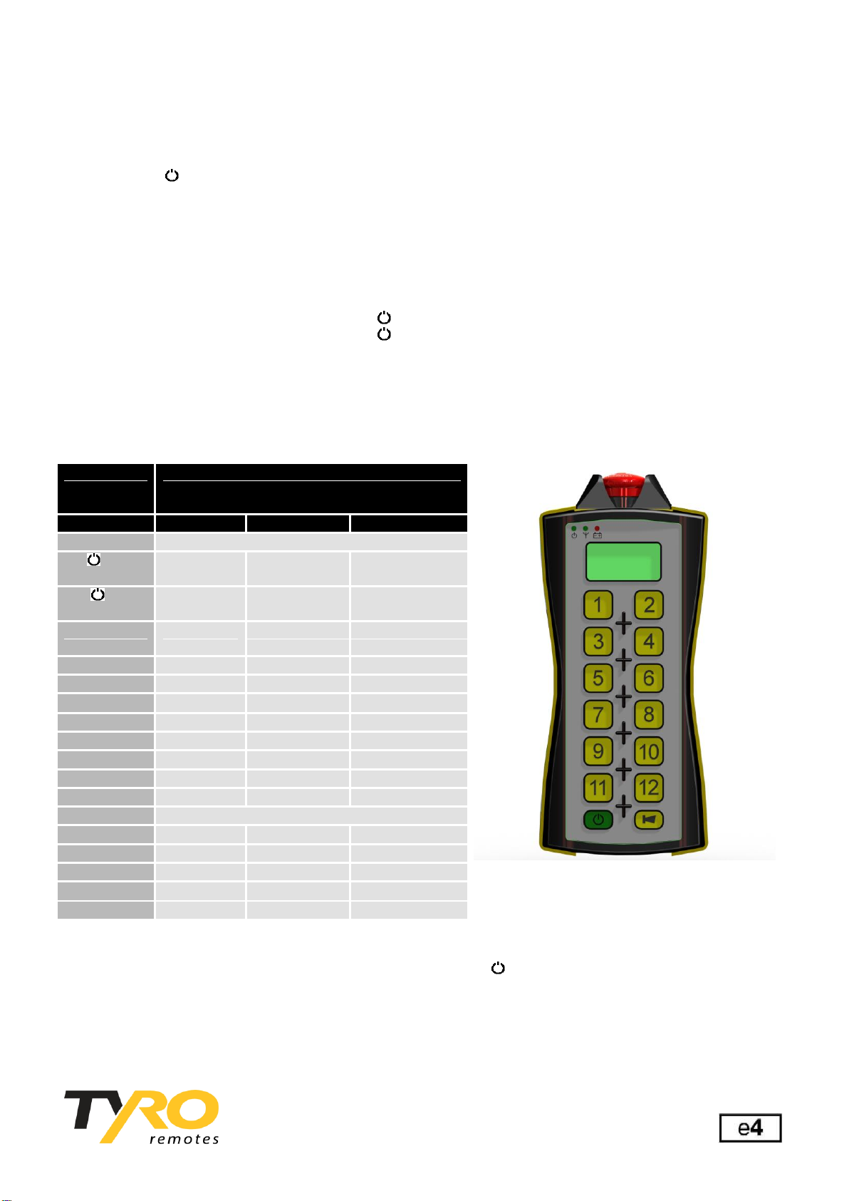
Cetus transmitter and Norma receiver
Number of functions: 12x pulse, ON/OFF, claxon, emergency stop button.
On LED: Lights up if the receiver (and the transmitter) is on, flashes if the receiver is off.
Aerial LED: Lights up when a function button is pressed (not confirmation of receipt).
Battery LED: Normally off but flashes if battery is almost empty (10%).
Battery LED: Flashes during charging, even when fully charged.
Emergency stop button: Switches line relays Q1 and Q2 of PLC 1 off, so that you can serial switch your emergency
stop circuit.
Buttons
Activate the Cetus transmitter: Keep the button pressed down for 2 seconds.
Deactivate the Cetus transmitter: Keep the button down for 2 seconds or press the emergency stop button.
Assembly
To optimise the range of the Cetus transmitter, we recommend that the aerial of the Norma receiver be placed as
high up as possible and free of metal objects. After connection and assembly, test first before switching on the
mains power. The cable connection is as follows:
*Please note: specific systems tailor-made for
clients may vary from this configuration. Please
see the document “client-specific configuration”
Blocking buttons:
The standard system is that the buttons are blocked horizontally. It is then not possible to switch buttons 1&2, 3&4,
5&6, 7&8, 9&10, 11&12 at the same time. The claxon, on/off button and emergency stop button are not affected
by this. Optionally, this block can be cancelled.
Rechargeable handheld transmitter:
For optimum operation we recommend you recharge the transmitter every day.
Cetus
transmitter
12
Norma receiver:
1x 10R + 1x 5R PLC
Button
Relay
Relay input
Relay output
PLC 1
On
1+2
activated
C1 & C2
Q1 & Q2
Off
1+2
deactivated
C1 & C2
Q1 & Q2
Emergency
stop
1+2
deactivated
C1 & C2
Q1 & Q2
13 Claxon
3
C3
Q3
1
4
C4
Q4
2
5
C5
Q5
3
6
C6
Q6
4
7
C7
Q7
5
8
C8
Q8
6
9
C9
Q9
7
10
C10
Q10
PLC 2
8
1
C1
Q1
9
2
C2
Q2
10
3
C3
Q3
11
4
C4
Q4
12
5
C5
Q5
Manual
Tyro Cetus/Norma 12 functions simplex remote control
Page 2/5
Tyro Remotes Tel: +31-(0)546-588790
Bedrijvenpark Twente 1-B Fax: +31-(0)546-579490
The Netherlands Website: www.tyroremotes.eu
Standard delivery (in the standard configuration)
Technical specifications:
Standard
Cetus transmitter without a LCD
Norma receiver without a keyboard
868 Mhz aerial
230V Car kit or Adapter
12 function buttons + 1(claxon)
Pulse switched
Horizontal button block
Neversleep (transmitter remains on)
Button icons 1/12 to be determined by the client
Cetus Transmitter
Max. charging voltage
26Vdc
Min. charging voltage
12Vdc
Battery standby time
± 200 hours
Battery operating time
± 32 hours
Normal charging time
± 5 hours
IP classification
IP65
Transmission range
up to 300 metres
Weight
452 grams
Size
235x105x45 mm
Operating frequency
868 Mhz
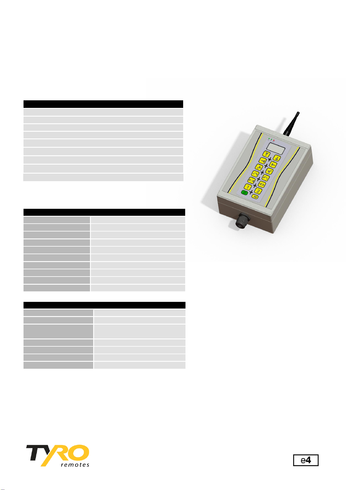
Norma Receiver
Connection voltage
10-38Vdc
Max. output power
3A (with 24 Vdc)
Power consumption per
I/O Board
Max. 1A
IP classification
IP-66
PLC
10 + 5 Relays
Weight
1066 grams
Size
240 x 160 x 92 mm
Manual
Tyro Cetus/Norma 12 functions simplex remote control
Page 3/5
Tyro Remotes Tel: +31-(0)546-588790
Bedrijvenpark Twente 1-B Fax: +31-(0)546-579490
The Netherlands Website: www.tyroremotes.eu
PLEASE NOTE: All the systems have already been programmed ex works
Programming an additional or a new Cetus transmitter to the Norma receiver
If you want to reprogram the Cetus transmitter and Norma receiver because you want to program an additional or
new Cetus transmitter to the Norma receiver, please do so as follows:
Step
Description
1.
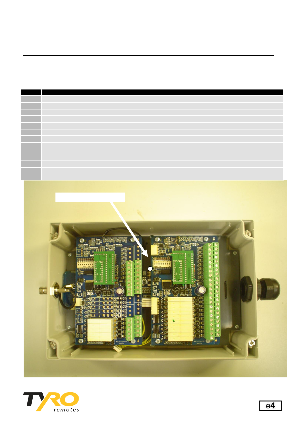
Unscrew the Norma receiver casing and open it.
2.
You will now see 3 printed circuit-boards next to each other and one underneath.
3.
Connect the power cable to the V+ screw clamp of the Norma receiver (see diagram).
4.
Connect the earth cable to the V- screw clamp of the Norma receiver (see diagram).
5.
You will see a white button on the lower PC board (see diagram below).
6.
Keep this white button pressed down (also during the following steps).
7.
Keep the white button pressed down whilst you once again switch on the voltage on the receiver.
8.
Continue to keep the white button pressed down whilst you switch on the Cetus transmitter, you will now
hear the relay clicking. If you keep the white button pressed down for longer than 10 sec., all the Cetus
transmitters will be deleted.
9.
Now release both buttons, the system is programmed and ready for continuous use.
10.
If you want to register several Cetus transmitters on the Norma receiver, then you have to repeat steps
7 to 9 for each Cetus transmitter.
Programming button

Manual
Tyro Cetus/Norma 12 functions simplex remote control
Page 4/5
Tyro Remotes Tel: +31-(0)546-588790
Bedrijvenpark Twente 1-B Fax: +31-(0)546-579490
The Netherlands Website: www.tyroremotes.eu
Analysis of failures
Check that the transmitter is charging: the battery LED should flash during charging.
If this is not the case, check the charger, power source and plug connections.
Check whether the transmitter is functioning: the aerial LED will be lit if the transmitter is on and you press a button.
If this is not the case, check the rechargeable battery.
Check whether the receiver is on: The on LED ( ) on the transmitter is lit if the receiver is on and flashes if the
receiver is off. If the on LED is flashing, check the power source of the receiver V+. Also check whether the range is
being hindered (hold the transmitter right next to the receiver to rule this out).
Check whether the transmitter is still registered on the receiver by using the steps on page 3.
Check whether there is power on the outputs (Q1/Q10).
If the system is still not working properly, go to www.tyroproducts.nl “Support” for more information or consult your
supplier. This document can also be downloaded from the aforementioned website.
Optimising the range
Radio waves can be hindered by the following: metal objects, damp (trees) and other radio waves.
- Check that the aerial is making contact properly.
- Make sure that there are as few metal objects as possible around the aerial. In any case try to prevent any
obstacles between the transmitter and receiver aerial. Place the receiver’s aerial as high as possible. If necessary,
use an aerial extension cable to do so.
- In very damp areas, the range is a lot shorter; you should take this into account.
- Other transmitters can also reduce the range. Try to avoid having systems next to each other that operate on the
same frequency. Above all systems that transmit continuously or systems with out of range protection are troubled
by this. Try to stay away from radio/TV masts.
Conditions
All deliveries shall occur in accordance with the general terms and conditions of sale, which you can request from us
or download from the website. Our products are certified for many applications. During assembly you should take
into account the Machinery Directives that apply for your application.

Manual
Tyro Cetus/Norma 12 functions simplex remote control
Page 5/5
Tyro Remotes Tel: +31-(0)546-588790
Bedrijvenpark Twente 1-B Fax: +31-(0)546-579490
The Netherlands Website: www.tyroremotes.eu
I/O board Norma receiver connection diagram
Relay outputs
Depending on the type of control, more or fewer relays can be present on the PLC.
The relay contacts on the PLC are of the normally open (NO) type and are between Q and C in the terminal board.
The contact between Q1 and C1 belongs with relay 1, Q2 and C2 with relay 2, etc.
To see how the relays switch, only the supply voltage (V+ and V-) need be connected.
When using the buttons, the orange LEDs will now show which relay is switching.
Supply voltage
The positive supply voltage is connected to the V+ and the negative supply voltage (earth) to the V-.
The 4 V+ connections are connected to each other as are the 4 V- connections.
Figure 2
Digital inputs
If your control has been programmed for this, signals can be placed on i1 to i8 for feedback to the receiver, for
example like a stop switch.
Analog inputs
If your control has been programmed for this, analog voltage levels can be placed on a1 to a4 for feedback to the
receiver, for example like a potentiometer for level adjustment.
The analog voltage may vary between 0 and 10V.
To this end, use can be made of the reference voltage of 10V that is present on the aVr connection (max. 20mA!).
The 3 aVr connections are connected to each other.
Analog output
If your control has been programmed for this, in the case of proportional control, analog output voltage can be taken
from connection aO. This analog voltage may vary between 0 and 10V and is adjustable in 8 steps.
This manual suits for next models
1
Table of contents
Other Tyro Remote Control manuals


