U.S. General 92649 User manual

A/C MANIFOLD GAUGE SET
R134A
ASSEMBLY AND OPERATING INSTRUCTIONS
All technicians opening the refrigeration
circuit in automotive air conditioning systems
MUST be certified in refrigerant recovery and
recycling procedures in compliance with Section
609 of the Clean Air Act Amendments of 1990.
For additional information regarding ozone
depletion and air conditioning service regulations,
please visit EPA’s website:
http://www.epa.gov/ozone
In addition, service of air conditioning
systems can result in overfilling, creating
a serious EXPLOSION HAZARD, if done
by an untrained or inexperienced
technician.
REV 05f, 09i
Visit our website at: http://www.harborfreight.com
Read this material before using this product.
Failure to do so can result in serious injury.
SAVE THIS MANUAL.
Copyright©2004 by Harbor Freight Tools®. All rights reserved. No portion of this manual or any artwork
contained herein may be reproduced in any shape or form without the express written consent of Harbor Freight
Tools. Diagrams within this manual may not be drawn proportionally. Due to continuing improvements, actual
product may differ slightly from the product described herein. Tools required for assembly and service may not
be included.
For technical questions or replacement parts, please call 1-800-444-3353.
92649

Page 2SKU 92649 For technical questions, please call 1-800-444-3353
Specifications
Note: Accuracy of the Gauge is ± 2%
WARNING!! ONLY USE REFRIGERANT R-134A WITH THIS A/C MANIFOLD GAUGE SET.
Save This Manual
You will need the manual for the safety warnings and precautions, assembly instructions,
operating and maintenance procedures, parts list and diagram. Keep your invoice with this
manual. Write the invoice number on the inside of the front cover. Keep the manual and
invoice in a safe and dry place for future reference.
Safety Warnings and Precautions
WARNING: When using tool, basic safety precautions should always be followed to
reduce the risk of personal injury and damage to equipment.
Read all instructions before using this tool!
1. Keep work area clean. Cluttered areas invite injuries.
2. Observe work area conditions. Do not use tools in damp or wet locations. Do not
expose to rain. Keep work area well lit.
3. Keep children away. Children must never be allowed in the work area. Do not let
them handle the A/C Manifold Gauge Set.
4. Store idle equipment. When not in use, the A/C Manifold Gauge Set must be stored
in a dry location to inhibit rust. Always lock up this product and keep it out of reach of
children.
5. Use the right tool for the job. There are certain applications for which this A/C
Manifold Gauge Set was designed. It will do the job better and more safely at the rate
for which it was intended. Do not modify this A/C Manifold Gauge Set and do not use
this A/C Manifold Gauge Set for a purpose for which it was not intended.
6. Dress properly. Do not wear loose clothing or jewelry as they can be caught in
moving parts. Protective, electrically nonconductive clothes and nonskid footwear are
recommended when working. Wear restrictive hair covering to contain long hair.
7. Use eye, ear and hand protection. Always wear ANSI approved impact safety
goggles. Wear an ANSI approved dust mask or respirator when working around
chemical dusts and mists. Wear heavy duty work gloves with working with R134a
refrigerant.
REV 05f, 09i
Blue Gauge Low Side - 2-1/2” diameter, 0-120 PSI, 0-40 VAC
Blue Hose 1/4” FFL x 4’ 9” with knurled fittings and twist valve with quick disconnect
Red Gauge High Side - 21/2” diameter, 0-500 PSI
Red Hose 1/4” FFL x 4’ 9” with knurled fittings and twist valve with quick disconnect
Charging Hose Yellow, high pressure, 1/2” ACME x 4’ 9” with knurled fittings
Materials Steel, Aluminum, Brass, Acrylic Plastic, High Pressure Hose
Weight 4.5 Lbs.
Set includes Quick Disconnect Valves

Page 3SKU 92649 For technical questions, please call 1-800-444-3353
8. Do not overreach. Keep proper footing and balance at all times.
9. Maintain tools with care. Keep the A/C Manifold Gauge Set clean for better and
safer performance. Inspect hoses periodically, and if damaged, have them repaired
by an authorized technician.
10. Stay alert. Watch what you are doing, use common sense. Do not operate any tool
when you are tired.
11. Check for damaged parts. Before using any tool, any part that appears damaged
should be carefully checked to determine that it will operate properly and perform its
intended function. Check for alignment and binding of moving parts; any broken parts
or mounting fixtures; and any other condition that may affect proper operation. Any
part that is damaged should be properly repaired or replaced by a qualified technician.
12. Replacement parts and accessories. When servicing, use only identical
replacement parts. Use of any other parts will void the warranty. Only use accessories
intended for use with this tool. Approved accessories are available from Harbor Freight
Tools.
13. Do not operate tool if under the influence of alcohol or drugs. Read warning
labels if taking prescription medicine to determine if your judgment or reflexes are
impaired while taking drugs. If there is any doubt, do not operate the tool.
14. Maintenance. For your safety, service and maintenance should be performed
regularly by a qualified technician.
15. Industrial applications must follow OSHA requirements.
16. People with pacemakers should consult their physician(s) before using this
product. Electromagnetic fields in close proximity to a heart pacemaker could cause
interference to or failure of the pacemaker. In addition, people with pacemakers
should observe the following: Caution is necessary when near the coil, spark
plug cables, or distributor of a running engine. The engine should always be off if
adjustments are to be made to the distributor.
17. WARNING: The brass components of this product contain lead, a chemical
known to the State of California to cause birth defects (or other reproductive
harm). (California Health & Safety code § 25249.5, et seq.)
Warning: The warnings, cautions, and instructions discussed in this instruction manual
cannot cover all possible conditions and situations that may occur. It must be understood
by the operator that common sense and caution are factors, which cannot be built into
this product, but must be supplied by the operator.

Page 4SKU 92649 For technical questions, please call 1-800-444-3353
SPECIFIC PRODUCT WARNINGS AND PRECAUTIONS
WARNING!! ONLY USE REFRIGERANT R-134a WITH THIS A/C MANIFOLD GAUGE SET.
WARNING!! Never start an engine in an enclosed area (like a garage). A running
gasoline engine generates Carbon Monoxide; Carbon Monoxide is a colorless,
odorless gas that can cause serious injury and death, if inhaled.
1. Always keep hands and fingers away from the moving parts and hot parts of
vehicle’s engine.
2. Make sure to read and understand all instructions and safety precautions as
outlined in the vehicle manufacturer’s manual for air condition servicing. Only
qualified mechanics that are trained in servicing air conditioning systems
should use this product.
3. When warming up an engine in preparation for testing of the A/C system, make
sure the vehicle’s transmission is placed in “Park” and the emergency brake is
applied.
4. CAUTION! Refrigerant R-134a can cause severe frostbite if it comes in contact
with the skin. Always follow the safety warnings and instructions provided by
the manufacturer of R-134a refrigerant.
5. Never disconnect any hose while the hose is under pressure. Pressurized
R-134a refrigerant can cause severe injury.
6. Use caution when opening an air conditioning system line or can of
refrigerant. When testing, always place a towel around the service valves of the
air conditioning unit and High and Low Pressure Couplers (20 and 21) of the A/C
Manifold set.
7. Keep refrigerant away from excessive heat as pressure in the container could
increase enough to rupture the can.
8. Never discharge refrigerant into the atmosphere. Always capture refrigerant
into an approved recovery container (not included), and then dispose of properly.
Contact your local Hazardous Waste Authority for disposal guidelines.
9. Only use refrigerant in a manner consistent with the air conditioning system’s
repair manual.
Unpacking
When unpacking, check to make sure the parts listed on page 8 are included. If any parts
are missing or broken, please call Harbor Freight Tools at the number on the cover of this
manual as soon as possible.

Page 5SKU 92649 For technical questions, please call 1-800-444-3353
PRODUCT OVERVIEW
1. The A/C Manifold Gauge Set is designed to test automotive air conditioning systems.
By comparing the high side and low side pressure reading to the vehicle manufacturer’s
A/C system specifications, a probable faulty condition may be determined.
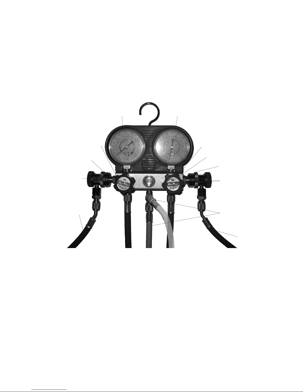
2. The High Pressure Gauge (3) is used to measure compressor discharge pressure.
The Low Pressure Gauge (5) is used to measure suction, or low side pressure. (See
FIGURE 1 on page 6.)
3. The Red and Blue Thumb Handles (11) control the flow of refrigerant to and from the
Yellow Refrigeration Charging Hose (18), also called the Service Hose. The actual use
of these Thumb Handles will not be explained in this manual. (See FIGURE 1.)
4. The valves on the Red High Pressure Coupler (22) and Blue Low Pressure Coupler (23)
control the input to the High Pressure Gauge (3) and Low Pressure Gauge (5) from the
Red High Pressure Hose (17) and Blue Low Pressure Hose (19). (See FIGURE 1.)
5. The Yellow Refrigeration Charging Hose (18), also called Service Hose, is connected
to a vacuum pump for purging the system (cleaning or evacuating). The Yellow Refrig-
eration Charging Hose (18) also is connected to a container of R-134A Refrigerant for
charging (filling) the system. For testing, the Yellow Hose (18) not used and is attached
to both branches of the T-fitting (16) on the Manifold Body (2) (see FIGURE 1).
6. General instructions for testing an A/C system are outlined in this manual. Specific
procedures for each individual system type and model should be referenced in the
vehicle manufacturer’s specific A/C system service manual.
7. Although this kit may have some utility in these procedures, instruction is NOT provided
for the evacuation and recovery of the system. All technicians opening the refrigeration
circuit in automotive air conditioning systems MUST be certified in refrigerant recovery
and recycling procedures - see box on front cover.
Operation
Refer to the Assembly Drawing on page 8.
To Conduct a Static A/C Pressure Reading:
1. Make sure the vehicle’s engine is NOT running, and the A/C system is OFF.
2. Turn the Red Thumb Handle (11) and BlueThumb Handle (11) clockwise, to the CLOSED
position. See FIGURE 1 on page 6.
WARNING: DO NOT, AT ANY TIME, OPEN the Thumb Handles (11) or refrigerant will be
leaked to the atmosphere and the A/C system may become contaminated.
3. Note: Before connecting the Red High Pressure Coupler (22) and the Blue Low Pres-
sure Coupler (23) make sure the Control Valves are closed. To close, turn each control
valve counterclockwise.
4. Connect the Red High Pressure Coupler (22) to the A/C system high side line.
See FIGURE 1 on page 6.
5. Connect the Blue Low Pressure Coupler (23) to the A/C system low side line.
See FIGURE 1 on page 6.
6. Connect both ends of the Yellow Refrigeration Charging Hose (18) to both branches of
the T-fitting (16) on the Manifold Body (2). See FIGURE 1 on page 6.
7. Turn the Control Valves of the Red High Pressure Coupler (22) and Blue Low Pressure
REV 05f

Page 6SKU 92649 For technical questions, please call 1-800-444-3353
NOTE: In the above photo both Low Pressure Hose (19) and High Pressure Hose (17)
are in the storage position and are attached to Solid Storage Connectors (6 & 7).
To Conduct a Performance A/C System Test:
1. A performance test indicates air conditioning system condition by measuring system
pressures with the engine running.
2. Turn the Red Thumb Handle (11) and Blue Thumb Handle (11) clockwise to the CLOSED
positions. See FIGURE 1, above.
WARNING: DO NOT, AT ANY TIME, OPEN the Thumb Handles (11) or refrigerant will be
leaked to the atmosphere and the A/C system may become contaminated.
3. Turn the Red Control Valve (22) and Blue Control (23) counterclockwise, to the CLOSED
position. See FIGURE 1 on page 6.
4. Connect the Red High Pressure Coupler (22) to the A/C system high side line. Connect
the Blue Low Pressure Coupler (23) to the A/C system on the low side line.
See FIGURE 1, above.
Operation (continued)
Coupler (23) clockwise to open.
8. Note: The pressure you see on both the high and low side gauges should be the same
or very close. Now, compare the reading taken to the reading as noted in the vehicle
manufacturer’s service manual.
9. Turn the Control Valves of the Red High Pressure Coupler (22) and Blue Low Pressure
Coupler (23) counterclockwise to close and remove the Couplers from the A/C
system.
10. Use care when disconnecting the Control Valves from the A/C system service fittings,
the hoses may contain some residual refrigerant.
FIGURE 1
Blue Low Pressure Gauge (5)
Blue Thumb Handle (11)
Blue Low Pressure Coupler (23)
Control Valve
Blue Refrigeration
Low Pressure
Hose (19)
Red High Pressure Gauge (3)
Red Thumb Handle (11)
Red High Pressure Coupler
(22)
Control Valve
Red
Refrigeration
High Pressure
Hose (17)
Yellow Refrigeration
Charging Hose (18)
(connect to both branches
of T-fitting (16))
Manifold Body (2)
REV 05f, 09i

Page 7SKU 92649 For technical questions, please call 1-800-444-3353
Operation (continued)
Maintenance
1. Before each use, inspect the general condition of the A/C Manifold Set. Check for
cracked or broken parts, damaged Hoses (17,18,19), and any other condition that may
affect safe operation. If a problem with the Set occurs, have it corrected before further
use. Do not use damaged equipment.
2. Periodically, clean with a damp cloth using a mild detergent or solvent.
3. When storing, keep the Set clean and dry. Also, connect the High Pressure Coupler
(22) and the Low Pressure Coupler (23) to its corresponding Solid Storage Connector
(6 & 7) to prevent contamination from entering the Set when not in use. See FIGURE
1on page 6 and the Assembly Drawing on page 8.
5. Connect both ends of the Yellow Refrigeration Charging Hose (18) to the T-fitting (16)
on the Manifold Body (2). See FIGURE 1, above.
CAUTION: Make sure that manifold and hoses are not in the way of cooling fan(s) or belts.
6. With the transmission in PARK and the emergency brake set, start and fast idle the
engine at approximately 1,500 RPM. CAUTION: Make sure this procedure is
conducted in a WELL VENTILATED area. Never perform a test in an enclosed
garage. The carbon monoxide emitted from a running engine is a colorless,
odorless gas that can cause injury and death if inhaled.
7. Set the A/C system for maximum cooling for about ten minutes to allow pressures to
stabilize. Close the vehicle’s doors and open all windows, and leave the hood fully open.
Place a temperature gauge (not included) in one of the air outlets in the passenger
compartment. Place another temperature gauge (not included) at the condenser to
measure ambient (outside) air temperature. Both temperatures are usually needed to
analyze A/C system performance.
8. Turn the Control Valves of the Red High Pressure Coupler (22) and Blue Low Pressure
Coupler (23) clockwise to open. See FIGURE 1, above.
9. Observe and note the reading on the High Pressure Gauge (3) and Low Pressure Gauge
(5). Then, compare that reading and the temperature on the temperature gauges to
the readings as noted in the vehicle manufacturer’s service manual. Note: Pressure
gauge readings vary with ambient air temperature, humidity, and system design. See
FIGURE 1 on page 6.
10. When finished, turn off the A/C and engine. Turn the Control Valves of the Red High
Pressure Coupler (22) and Blue Low Pressure Coupler (23) counterclockwise to close,
and remove the Couplers from the A/C system. See FIGURE 1 on page 6.
11. Use care when disconnecting the Control Valves from the A/C system service fittings,
the hoses may contain some residual refrigerant.
REV 05f, 09h

Page 8SKU 92649 For technical questions, please call 1-800-444-3353
NOTE: Some parts are listed and shown for illustration purposes
only and are not available individually as replacement parts.
PLEASE READ THE FOLLOWING CAREFULLY
THE MANUFACTURER AND/OR DISTRIBUTOR HAS PROVIDED THE PARTS DIAGRAM IN THIS MANUAL
AS A REFERENCE TOOL ONLY. NEITHER THE MANUFACTURER NOR DISTRIBUTOR MAKES ANY
REPRESENTATION OR WARRANTY OF ANY KIND TO THE BUYER THAT HE OR SHE IS QUALIFIED TO
MAKE ANY REPAIRS TO THE PRODUCT OR THAT HE OR SHE IS QUALIFIED TO REPLACE ANY PARTS
OF THE PRODUCT. IN FACT, THE MANUFACTURER AND/OR DISTRIBUTOR EXPRESSLY STATES THAT
ALL REPAIRS AND PARTS REPLACEMENTS SHOULD BE UNDERTAKEN BY CERTIFIED AND LICENSED
TECHNICIANS AND NOT BY THE BUYER. THE BUYER ASSUMES ALL RISK AND LIABILITY ARISING
OUT OF HIS OR HER REPAIRS TO THE ORIGINAL PRODUCT OR REPLACEMENT PARTS THERETO,
OR ARISING OUT OF HIS OR HER INSTALLATION OF REPLACEMENT PARTS THERETO.
Parts List
Part Description Qty. Part Description Qty.
1 Rubber Cover 1 13 Window Glass 1
2 Manifold Body 1 14 Ring Nut 1
3 High Pressure Gauge 1 15 Connector 2
4 Hook Set 1 16 Tee Fitting 1
5 Low Pressure Gauge 1 17 Ref. High Pressure Hose Red 1
6 Solid Storage Connector (Low Press.) 1 18 Ref. High Pressure Hose Yellow 1
7 Solid Storage Connector (High Press.) 1 19 Ref. Low Pressure Hose Blue 1
8 Valve Seat 2 20 Connector 2
9 Valve Stem 2 21 O-Ring 2
10 Valve Nut 2 22 High Pressure Coupler & Valve (Red) 1
11 Thumb Handle 2 23 Low Pressure Coupler & Valve (Blue) 1
12 O-Ring 1
Assembly Diagram
REV 05f, 09h

Page 9SKU 92649 For technical questions, please call 1-800-444-3353
LIMITED 90 DAY WARRANTY
Harbor Freight Tools Co. makes every effort to assure that its products meet high quality
and durability standards, and warrants to the original purchaser that this product is free from
defects in materials and workmanship for the period of 90 days from the date of purchase.This
warranty does not apply to damage due directly or indirectly, to misuse, abuse, negligence or
accidents, repairs or alterations outside our facilities, criminal activity, improper installation,
normal wear and tear, or to lack of maintenance. We shall in no event be liable for death, in-
juries to persons or property, or for incidental, contingent, special or consequential damages
arising from the use of our product. Some states do not allow the exclusion or limitation of
incidental or consequential damages, so the above limitation of exclusion may not apply to
you.THIS WARRANTY IS EXPRESSLY IN LIEU OF ALL OTHER WARRANTIES, EXPRESS
OR IMPLIED, INCLUDING THE WARRANTIES OF MERCHANTABILITY AND FITNESS.
To take advantage of this warranty, the product or part must be returned to us with
transportation charges prepaid. Proof of purchase date and an explanation of the complaint
must accompany the merchandise. If our inspection verifies the defect, we will either repair or
replace the product at our election or we may elect to refund the purchase price if we cannot
readily and quickly provide you with a replacement. We will return repaired products at our
expense, but if we determine there is no defect, or that the defect resulted from causes not
within the scope of our warranty, then you must bear the cost of returning the product.
This warranty gives you specific legal rights and you may also have other rights which
vary from state to state.
3491 Mission Oaks Blvd. • PO Box 6009 • Camarillo, CA 93011 • (800) 444-3353
REV 09f
Table of contents
Other U.S. General Power Tools manuals