U.S. Jack D-51404 User manual

INSTRUCTION MANUAL
AND PARTS SHEET
MODEL #: D-51404
1-TON TRUCK AND BUS TRANSMISSION
HANDLER HYDRAULIC JACK
NSN 4910-00-585-3622
1125 INDUSTRIAL COURT
BENTON HARBOR, MI 49022
WWW.USJACK.COM

OPERATING INSTRUCTIONS
1. Upon receiving jack, open release valve and pump
handle several times. This will eliminate any
airbound condition that may have occurred during
shipment.
2. To raise jack, close release valve and operate
pump handle.
3. To lower, open release valve.
FIND CENTER OF GRAVITY
In handling the newer large transmission, it will be not-
ed that they have grown considerably in length. It is
important, first, to gauge as accurately as possible the
center of gravity of the unit to be removed where you
will want to place the jack adapter. On many transmis-
sions this center of gravity is identified by small
projecting lugs on the bottom of the case. On others it
is located on the drawing of the transmission included
in the truck service manual. In any case, you will find it
to be toward the rear of the case, from the center. It is
important that the transmission be generally in balance
when being supported by the jack.
PREPARE TRANSMISSION FOR REMOVAL
1. Prepare transmission for removal in normal
manner, by dropping drive shaft, removing project-
ing levers, accessories ect., and other components
of the truck which might interfere when the
transmission is lowered. If desired, the parking
brake assembly may be removed also.
2. Remove all but three or four bell housing bolts,
leaving those near the top, which can be reached
when the jack is in place.
JACK PLACEMENT AND OPERATION
1. Place jack beneath transmission case as near to
the center of balance as possible. This normally is
rearward of the dimensional center of the unit.
2. Place triangle support brackets against transmis-
sion. Insert four bolts in nearest support plate
holes and fasten with four tightening knobs.
3. Transmission case bottom must rest firmly on jack
support plates. If necessary, due to transmission
case irregularities, the jack adaptor may be tilted
forward, backward, or from sided to side to match
bottom contour of transmission case. his tilt
adjustment is accomplished through adjustment
screw, located on the end of the lift arm below the
adaptor.
4. With transmission bottom on adapter plate, slide
triangle support to firmly support transmission.
(It is important to secure bolt knobs with wrench.)
Securely fasten safety chain to hold transmission
firmly in place while removing.
5. With jack firmly supporting transmission, complete bell
housing bolt removal. Frequently this joint is firmly
stuck together and must be forced slightly to break
loose. This may be done with the jack by raising then
lowering slightly.
6. When transmission has been lowered, it may be
necessary, depending on the size of the unit, to jack
up the front or rear axle of the truck to get the
transmission out from under the truck.
7. Replacement of the transmission is performed in
reverse order to removal. Keep in mind the adaptor
tilt features which permit minute adjustment for
alignment.
SAFETY IN-
STRUCTIONS
1. Do not overload. Overloading can cause damage to
or failure of the jack.
2. This jack is designed for use only on hard level
surfaces capable of sustaining the load. Use on other
than hard level surfaces can result in jack instability
and possible loss of load.
3. When the jack is used for transporting a load, the lift
arm must be in its lowest position. Roll only on hard
level surface free of excessive crevices or
obstructions.
4. Failure to heed these warnings may result in loss of
load, damage to jack and/or failure resulting in
personal injury or property damage.
Page 2 of 8
Repair Kit 5-569
Power Unit 5-51903
Forward and Backward
Tilt Adjusting Knob

FAILURE TO OPERATE
1. Release may not be completely closed.
2. Air-bound—see instruction No. 1.
3. Foreign matter in valve line—Repeat instruction
No.1
4. Too much oil—Lower to filler screw level.
5. Interior parts may be worn allowing oil to bypass.
Contact nearest Authorized Service Center.
MAINTENANCE AND LUBRICATION INSTRUCTIONS
1. Periodically check fluid level in power unit. Filler
plug is behind back cover which is removable with
four screws. Fluid level should be checked with lift
arm in lowest position and with unit on a level
surface. Fill to pipe plug level with recommended
hydraulic fluid.
2. Keep all moving parts clean and well lubricated.
Screw threads on tilt mechanisms require periodic
cleaning and lubricating if used in extremely dirty
areas.
3. Check all links and structural members for damage
or excessive wear.
TO REMOVE POWER UNIT—5-51903
1. Remove roll pin on bridge block at front of ram
2. Disconnect handle socket pin on top of pump piston
assembly.
3. Disconnect release knob by removing groove pin.
4. Remove “U” bolt at front of power unit.
5. Remove two (2) bolts holding base to frame.
SETTING THE RELIEF VALVE—See Figure 1
To set the relief valve, turn in the relief valve screw until
tight. Pump the power unit until the support plates are at
a height of 10 inches. Place a load of 2500 lbs. on the
support plates. Lift the load to see if the unit is function-
ing properly. While pumping, slowly turn out the relief
valve screw until the load cannot be lifted. The unit is
now set to lift a maximum of 2500 lbs. Place the
expansion plug in the relief valve hole to cover the screw
and prevent tampering.
After the unit has been rebuilt, an extended load test
should be run to determine if all parts have been
assembled and tightened correctly. The support plates
should be loaded with 2000 lbs. And the lift arm placed
at a height of 10 inches. The drop of the support plates
after a 30 minute period should not exceed .008 inches.
TROUBLE SHOOTING THE POWER UNIT
The following schematic drawings and reasons for
malfunction are a guide for solving power unit operation
problems.
SEE FIGURES 2 AND 3 on Page 4
A. POWER UNIT WILL NOT HOLD THE LOAD
When the power unit is under a load, the oil that is
supporting the load is trapped in the cavity bounded by the
ram, the release valve, and the discharge ball. If the oil is
escaping from that cavity, the jack will slowly retract.
Places from which oil can be escaping are:
1. The release valve, if it is not fully closed or if the seat is
damaged.
2. The ram packing, if it is worn out or damaged.
3. The discharge valve, if the seat is damaged or a for-
eign particles is holding the ball off its seat. If the suc-
tion valve is working, this normally results in a “handle
raiser”.
4. The valve block casting, if it is porous and incapable of
confining high pressure fluids.
5. The ram cylinder, if it is not turned in tight enough to
seal on the base.
6. The release insert, if it is not turned in tight enough to
seal in the base.
7. The relief valve, if it is not properly set or if the seat is
damaged.
B. RAM WILL NOT MOVE WHEN HANDLE IS PUMP.
This could be due to one of the following:
1. There is no oil in the reservoir or oil is low in the
reservoir. The oil level should be up to the filler plug
hole.
2. The intake valve is not functioning. The ball is either
jammed into the seat and will not dislodge or the ball is
being held off the seat by foreign materials and the oil
merely swishes back and forth.
3. Power unit is air bound. Every jack has air in the
reservoir, along with the oil. As long as the air stays at
that location, it does not cause any trouble. However, if
air finds its way to any other part of the system, the jack
might become air bound.
When a large air bubble forms between the intake and
pressure ball, the jack usually becomes inoperable. As the
pump moves up and down trying to pump oil, the bubble
just expands and contracts, preventing the formation of a
vacuum in the pump chamber and halting the flow of oil
from the reservoir.
A large bubble under the ram is not nearly as damaging,
but it gives the ram an annoying “bouncy” action.
To bleed the system of air, make sure the unit is on a level
service. With no load on the unit, pump to full height and
open the relief valve wide to lower the unit. Remove the
reservoir plug to allow any excess air to escape. Repeat
this several times and all air should be removed from the
pumping chamber.
Page 3 of 8

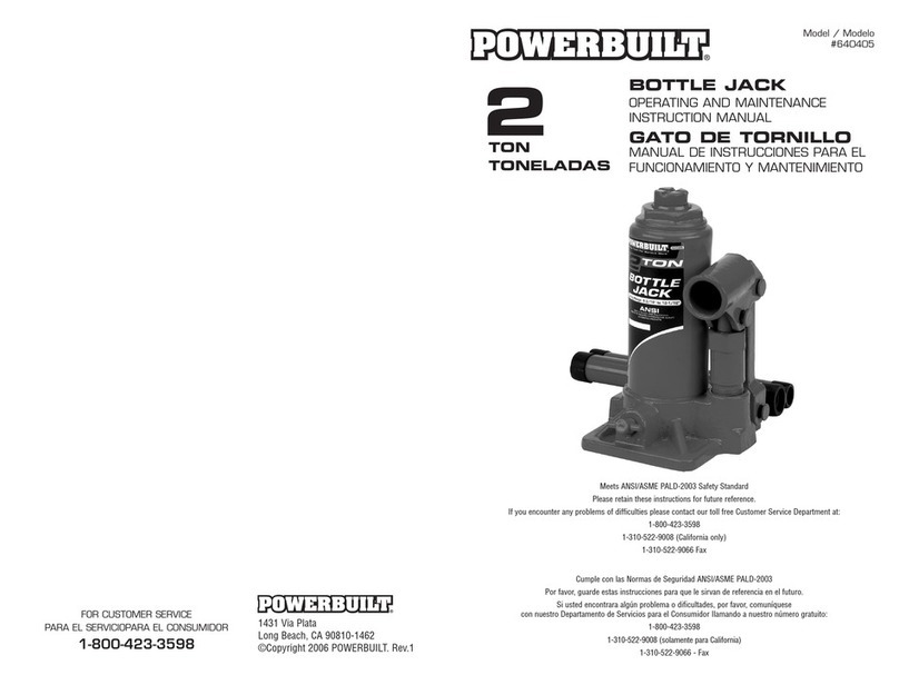
TRANSMISSION LIFT STRUCTURAL DIMENSIONS
Length…………… 47 inches
Width…………… 23.5 Inches
Low Height…… . 10 inches
Raised Height… 35 Inches
Lifting Range…… 25 inches
Plate Tilt Angle… 15 degrees All directions
Appx. shipping weight 255 Pounds
NOTE: Low and raised heights are measured from the floor to the top of the support plate and do not
include additional height of accessories.
THEORY OF OPERATION
A single piston activated by a lever arm operated during the entire lifting cycle, applies hydraulic pres-
sure to the bottom side of the ram piston at the full extension of the ram; fluid is by-passed through a
bleed hole located at the top of the ram assembly, through a passageway in the shell and casting, and
evacuates to the reservoir. If the operator attempts to raise a load which exceeds the capacity of the
device, fluid pressure builds up on the bottom face of the ram, pump and piston and spring loaded ball
and valve assembly. When the pressure exceeds the cracking pressure of the adjustable relief valve,
hydraulic fluid is evacuated to the reservoir.
Figure 2
Figure 3
Page 4 of 8

Page 5 of 8

Page 6 of 8

Repair Kit 5-569 Power Unit 5-51903
ITEMS MARKED WITH * ARE
INCLUDED IN THE REPAIR KIT
U.S. JACK COMPANY
PARTS LIST D-51404
ITEM PART ITEM ITEM PART ITEM
NO. NO. DESCRIPTION REQD NO. NO. DESCRIPTION REQD
1 2-53332 EYE BOLT 2 52 2-54949 PISTON PUMP
2 2-45975 S HOOK 4 53* 10-11885 PISTON CUP
3 2-55017 SAFETY CHAIN 2 54* D-2027
PISTON CYLINDER WASHER
4 2-58434 BOLT 4 55* D-7270 EXPANSION PLUG
56* D-2099-7 "O" RING
6 2-58730 WASHER 8 57 2-54954 RELIEF VALVE SCREW
7 2-58731 LOCK WASHER 8 58* D-7232 OVERLOAD SPRING
8 2-58601 ADJUSTER WHEEL 4 59* 2-54219 OVERLOAD PLUNGER
9 2-59992 PLATE 2 60* D-2071 BALL 1/8 DIA.
12 2-58268 BOLT 4 61 10-10169 RELEASE KNOB
13 2-45859 WASHER 6 62* 2-58745 ROLL PIN
14 2-45857 HEX NUT 5/8-18 4 63 56105 STEM
15 4-45943 SADDLE ASSEMBLE 64* D-2099-5 "O" RING
16 2-45862 TILT ADJ. SCREW 65* 10-12399 BALL
17 2-45957 TILT WHEEL 66 2-58436 RELEASE
18 4-45858 PIN .128 X.94 4 67* D-2099-6 "O" RING
19 2-45967 SPACER 68 56106
RELEASE STEM ASSEMBLY
20 2-45935 CONNECTING LINK 2 69 4-58462 INSERT ASSEMBLY
21 2-45855 BRIDGE BLOCK 70 56107 COMPLETE ASSEMBLY
22 D-6049-A RETAINING 3/4 6 71* D-2070 BALL 5/16 DIA.
23 D-7254 RETAINING 1/2 2 72* D-2074 BALL 7/32 BALL DIA.
24 D-8263 SIDE TILT SHAFT 73 D-5096 LOCK WASHER 1/4" 2
25 2-58448 NUT 2 74 SJ-5628 HEX NUT 1/4-20 2
26 4-45969
PLATFORM ASSEMBLY 75 D-6049-A RETAINING RING 3/4 2
27 D-7674 ROLL PIN 1/4 x 1-1/4 76 2-45956 SADDLE SHAFT
28 D-8206 BRIDGE BLOCK 77 19-10809 LIFT ARM ASSEMBLY
29 10-10599 LIFT ARM LINK 2 79* 2-58541 CLIP PIN 3
31 D-8211 LIFT ARM LINK PIN 2 80* 10-12019 LINK PIN 2
32 10-10635 "U" BOLT 82 4-59103
HANDLE SOCKET ASSEMBLY
33 10-10600 RESERVOIR HEAD 83 2-59102 HANDLE SOCKET LINK
34 19-12966 SERVICE PUMP ASSEMBLY 84* 10-10801 PUMP SWIVEL PIN
35* D-2099-25 "O" RING 85 10-10597 PUMP SWIVEL
36 10-10594 RESERVIOR 86 2-50576 RETAINING RING
37 10-10595 RAM CYLINDER 87 10-10637
MACHINE SCREW 10-24 x 3/8 8
38 10-10589 RAM CYLINDER 88 10-10633 ANGLE BRACKET 4
39 D-2835-A RAM SPACER 89 10-10613 BACK COVER
40* D-6437 BACK UP WASHER 91 D-7279
CAP SCREW 1/2-20 x 1-1/4 2
41* D-2834-A RAM CUP 92 D-6094 LOCK WASHER 1/2 2
42 D-2836 RAM CUP RETAINER 93 10-10949 CASTER WHEEL 4
43 D-2637 JAM NUT 95 2-55235 LOCK WASHER 4
44 10-10588 PUMP BASE 96 D-6041 JAM NUT 3/4-16 4
45* 10-10342 PIPE PLUG 1/4-18 97 10-10606 SIDE FRAME BUSHING 2
46 5-51903 POWER UNIT ASSEMBLY 99 D-7440 LOCK WASHER 2
48 4-54950 PUMP PISTON ASSEMBLY 101 19-10806 FRAME ASSEMBLY
49 10-11740 PACKING NUT
50* D-2099-10 PUMP WIPER
51 10-10598 PUMP CYLINDER
47 19-12965 PUMP ASSEMBLY 100 10-10605 LIFT ARM HINGE PIN
Page 7 of 8

LIMITED WARRANTY
The manufacturer warrants its products against defective material and workmanship for 2 years from the
date of original sale to the Buyer without charge provided that the equipment is shipped, transportation
charges prepaid, with proof of date of purchase, to the nearest Authorized Service Depot for inspection. (Do
not return to the factory). The Consumer’s remedies under this warranty are limited to repair or replacement
of parts at the option of the Manufacturer and its designated Authorized Service Depot. This warranty does
not cover units that have been altered or attachments added to them which are not recommended by the
Manufacturer. Use hydraulic jack oil only; use of other fluids voids this warranty as does unreasonable or
improper use, such as overloading, or any other abusive practice or accident.
The duration of any implied warranties arising under state law, including implied warranties or merchantabil-
ity or fitness for any particular purpose, are expressly limited to the duration of this written warranty.
In the event that the goods sold hereunder are defective or fail to conform to this written warranty or any
implied warranty, and recovery of consequential damages is expressly excluded except as such exclusion
is expressly prohibited by state law.
WARNING
A. THIS DEVICE IS A LIFTING DEVICE ONLY. THE LOAD SHALL BE
SUPPORTED IMMEDIATELY BY OTHER APPROPRIATE MEANS.
B. DO NOT OVERLOAD. OVERLOADING CAN CAUSE DAMAGE TO
OR FAILURE OF THE JACK.
C. LIFT ONLY ON AREAS OF THE VEHICLE AS SPECIFIED BY THE
VEHICLE MANUFACTURER.
D. THIS JACK DESIGNED FOR USE ONLY ON HARD, LEVEL
SURFACES CAPABLE OF SUSTAINING THE LOAD. USE ON
OTHER THAN HARD, LEVEL SURFACES CAN RESULT IN JACK
INSTABILITY AND POSSIBLE LOSS OF LOAD.
E. FAILURE TO HEED THESE WARNINGS MAY RESULT IN LOSS
OF LOAD, DAMAGE TO THE JACK, AND/OR FAILURE
RESULTING IN PERSONAL INJURY OR PROPERTY DAMAGE.
1125 Industrial Court Benton Harbor, MI 49022
PH 269-925-7777 Fax 269-925-6656
www.usjack.com
Table of contents
Other U.S. Jack Jack manuals