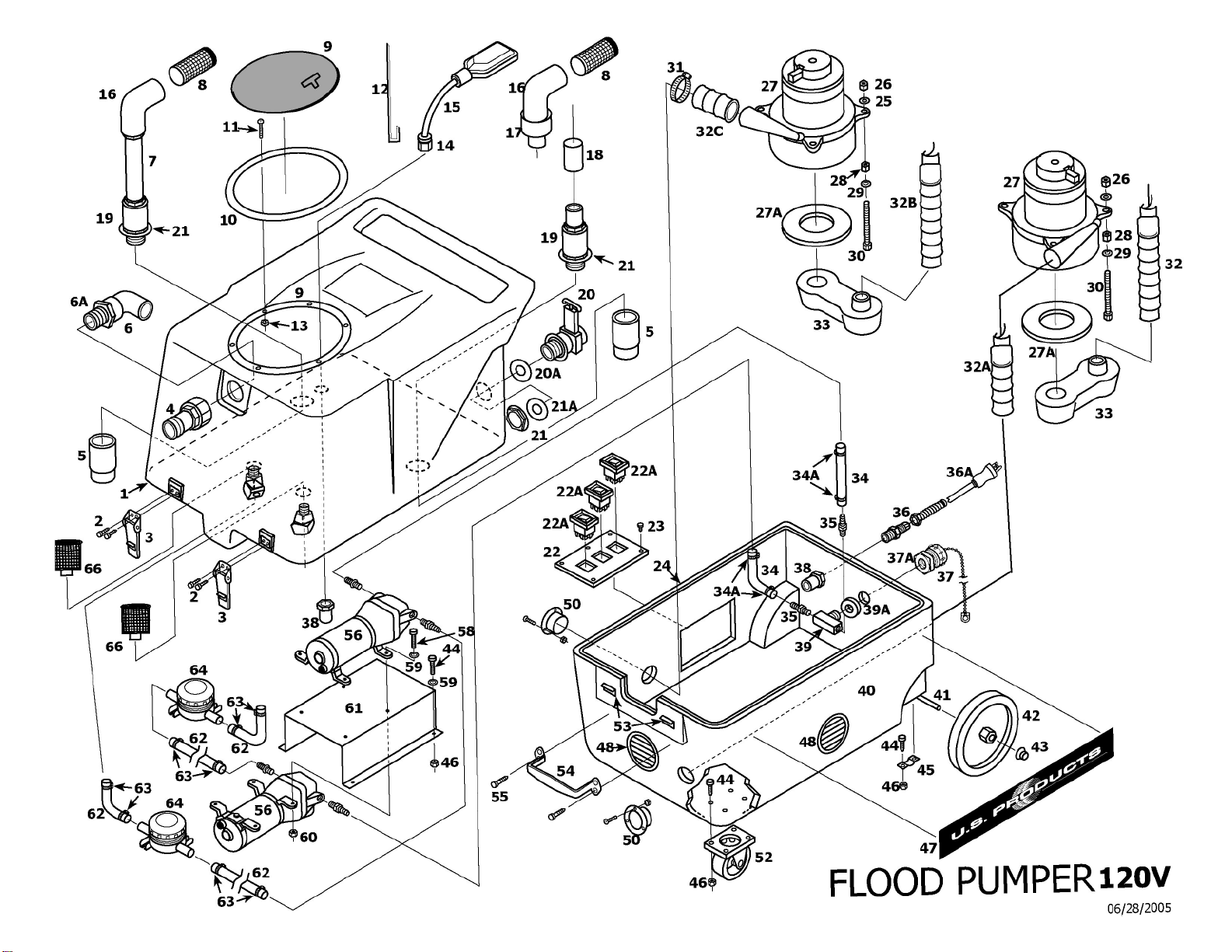
U.S. Products Flood Pumper Operating instructions

DO NOT OPERATE MACHINE UNTIL YOU HAVE READ ALL SECTIONS OF THE
INSTRUCTIONS. IMPROPER USE OF THE MACHINE WILL VOID THE WARRANTY
1. Always use a defoamer when foaming occurs to prevent vacuum motor damage.
2. Always be sure to remove the cap on the pump-out fitting, and connect the dump
hose, before turning the pump(s) on.
3. Keep all filters clean. Do not operate the machine if the filters are clogged.
4. Keep machine from rain and snow, extremes in temperatures, and store in a
heated location.
5. Do not let pump run dry for extended periods of time.
December 5, 2005
FLOOD
PUMPER
120V
INFORMATION
&
OPERATING
INSTRUCTIONS

IMPORTANT SAFETY INSTRUCTIONS
This machine is only suitable for commercial use, for example in hotels, schools, hospitals,
factories, shops and offices other than normal residential housekeeping purposes.
When using any electrical appliance, basic precautions should always be followed, including
the following:
NOTE: Read all instructions before using this machine.
WARNING!
To reduce the risk of fire, electric shock, or injury:
•Do not leave the machine unattended when it is plugged in. Unplug the unit from the
outlet when not in use and before servicing.
•To avoid electric shock, do not expose to rain or snow. Store, and use, indoors.
•Do not allow to be used as a toy. Close attention is necessary when used near children.
•Use only as described in this manual. Use only the manufacturer’s recommended at-
tachments.
•Do not use with damaged cord or plug. If the machine is not working as it should, has
been dropped, damaged, left outdoors or dropped into water, return it to a service cen-
ter.
•Do not pull by the cord, use the cord as a handle, close a door on the cord, or pull the
cord around sharp edges or corners. Do not run the machine over the cord. Keep the
cord away from heated surfaces. To unplug, grasp the plug, not the cord.
•Do not handle the plug, the cord, or the machine with wet hands.
•Extension cords must be 12/3 and no longer than 50 feet. Replace the cord or unplug
immediately if the ground prong becomes damaged.
•Do not put any object into openings. Do not use with any opening blocked; keep free
of dust, lint, hair, and anything that may reduce air flow.
•Keep loose clothing, hair, fingers, and all parts of body away from openings and moving
parts.
•Do not pick up anything that is burning or smoking, such as cigarettes, matches, or hot
ashes, or any health endangering dusts. Do not use to pick up flammable or combus-
tible liquids such as gasoline or use in areas where they may be present.
•Turn off all controls before unplugging.
•Connect to a properly grounded outlet only.
•Check hose clamps regularly to make sure they are tight. The pump discharges water at
high pressure. If a hose clamp becomes loose, the hose could also come loose, or all
off of the hose barb, and leak water into the base compartment
•Liquid flowing from the dump hose may be dangerous as a result of its temperature,
pressure, chemical content, or contaminants.

NOTE: This machine is only suitable for commercial use, for example in hotels, schools,
hospitals, factories, shops and offices other than normal residential housekeeping purposes.
Record the serial number and model of your new Flood Pumper here:
(and be sure to
mail your warranty card)
Serial Number: __________________ Model: FLOOD PUMPER
Purchase Date:_____________
Write the name and phone number of the distributor from whom you purchased this
machine: _____________________________________
_____________________________________
_____________________________________
INSPECTION:
Carefully unpack and inspect your FLOOD PUMPER for shipping damage. Each machine is tested
and inspected before shipping. Any damage incurred during shipping is the responsibility of the
carrier. You should notify the carrier immediately if you notice damage to the box or to the machine
or parts.
MAINTENANCE:
Prior to each job, inspect the recovery tank filters, the in-line filters, the float, and the drain gate to
make sure every thing is clean and able to function properly. After each job, remove and clean both
the nylon mesh strainer at the vacuum inlet and the stainless steel filters in the bottom of the
recovery tank. Unscrew the clear caps off the in-line filters (located under the recovery tank) and
clean the screens often. Pump damage may occur if the filters become clogged.
Check hose clamps regularly to make sure they are tight. The pump discharges water at high
pressure. If a hose clamp becomes loose, the hose could also come loose, or fall off of the hose
barb, and leak water into the base compartment.
Lubricate the wheels, castors, latches, and quick disconnects with an all purpose silicone spray. The
vacuums and the pumps do not require any scheduled maintenance; however the vacuum motors
may require new brushes after 1000 - 1500 hours. Clean the body with an all purpose detergent,
and protect it with an automobile interior polish.

Recovery Tank
Access Lid
Recovery Hose
Connection Point
Latches
Castor
Wheel
Drain Gate
& Pump Out
Hose Connection
(on rear)
SET-UP: Connect the vacuum/recovery hose to the vacuum inlet hose barb on
the front of the recovery tank. Connect one or two of the dump hoses
to the hose fitting on the rear of the machine. Put the lid on the re-
covery tank. Plug the machine into a grounded outlet.
VACUUM OPERATION:
A switch is provided for each vacuum motor. The machine can
operate with either one or both vacuum motors running. If only one
vacuum is needed, use VAC 1; a one-way valve allows VAC 1 to
create a suction by preventing air from being pulled through VAC 2,
when VAC 2 is not running.
VACUUM SHUT-OFF:
When the recovery tank is full, the float system will shut off power to
the vacuum motor(s) to prevent water from entering the motor(s).
The float may not work properly if it is extremely dirty or if there is
foam in the tank. Once the tank is emptied sufficiently, the vacuums
will come back on automatically.
PUMP OPERATION:
Always be sure to uncap the pump-out fitting and connect the dump
hose before turning the pumps on. Failure to do so may result in
blown hoses or loose fittings; water will damage motors and switches.
The two diaphram pumps on your Flood Pumper work together.
When you turn the pump switch on, both pumps will run, and they will
continue to run until you turn them off. Do not let the pumps run dry
for extended periods of time.


FLOOD PUMPER 120V
PART LIST
#1 FP389 Recovery Tank, Complete
#2 382C Screw, Stainless Steel, 8-32" X 7/8"
#3 908 Latch
#4 2077 Hose Barb, Vacuum Inlet
#5 2073 Elbow, PVC, 2”
#6 2075 Adaptor, PVC, 1-1/2”
#7 935 Pipe, PVC
#8 929 Filter, Vacuum Inlet
#9 2070B Lid, with Ring** (see Misc.)
#10 1129 Gasket, for Lid** (see Misc.)
#11 382 Screw, 10/32 x 7/8”, S/S
#12 2082 Bracket, Float
#13 17 Lock Nut, Nylon, 10-32, S/S
#14 230 Retainer, Cord, Water Tight
#15 2068 Float Switch
#16 900 Elbow, PVC, 90 Degrees
#17 935 Pipe, PVC, 1-1/2 ID
#18 2081 Check Valve
#19 900A Reducer, PVC
#20 903 Drain Gate* (see Misc.)
#20A 187 O-Ring, Small
#21 185 Nut, Cast Aluminum
#21A 190 O-Ring, Large
#22 2006 Switch Plate
#22A FP311 Switch, Pump, Vacuum, w/Cover
#23 28 Screw, #4 x 3/8”
#24 FP228A Gasket, Base
#25 14 Washer, 3/16"
#26 8 Lock Nut, 1/4-20
#27 FP324 Vacuum Motor Complete w/Connectors
#27A 2013 Gasket, Vacuum Motor
#28 136 Nut, 1/4-20
#29 137 Washer, Lock, 1/4"
#30 135 Bolt, 1/4-20 x 3-1/2”
#31 156 Hose Clamp, Size 28
#32 1302 Hose, Vacuum, 2” x 13”
#32A 430 Hose, Vacuum, 2” x 9”
#32B 1301 Hose, Vacuum, 2” x 18”
#32C 430 Hose, Exhaust, 2” x 2”
#33 MA-6 Manifold, Black
#34 2079 Hose, 3/4”, Polywire, 11”
#34A 380 Hose Clamp
#35 378 Hose Barb, 3/4” x 1/2 m.p.t., Brass
#36 184 Cord Retainer
#36A 495A Power Cord, Yellow, 25’
#37 237 Cap, with Chain and Hose Connection
#37A 239 Adapter, 3/4” Hose x 3/8 m.p.t., Brass
#38 937 Reducer, PVC
#39 152 “T”, brass
#39A 152A Washer, Flat, S/S, 7/8”
#40 BS-6 Base, Black
ITEM PART # DESCRIPTION ITEM PART # DESCRIPTION
#41 910 Axle, 18-13/16”
#42 2003 Wheel, 8”
#43 27A Axle Cap, Black
#44 5 Bolt, 1/4-20 X 3/4”
#45 180 Bracket, Axle
#46 8 Lock Nut, 1/4-20
#47 2071 Label, USP
#48 928 Louver, 3”
#50 FP220 Flange, Exhaust, Complete
#52 2002 Castor, Swivel, 3”
#53 909A Latch Strike for Latch, S/S
#54 2010 Handle, Chrome
#55 193 Screw, 1/4-20 X 3/4”
#56 2067 Pump, Diaphram, Sump, Complete
#58 204 Screw, S/S, 12-24 X 1-1/4"
#59 14 Washer, 3/16”, Flat
#60 204A Lock Nut, 12-24, S/S
#61 2076 Bracket, Mounting, Pump
#62 2079 Hose, 3/4”, Polywire, 7”
#63 380 Hose Clamp
#64 2074 Filter, Pump, Inline, S/S
#66 2069 Filter, Pump, 60 Mesh, in Tank
Micellaneous Parts / Assessories
*FP231A Drain Gate Assembly, Complete
with O-Rings and Nut.
**2070 Lid with Ring (Machines made
before 8-03)
**2070A Gasket, for Lid (Machines made
before 8-03)
#919C Vacuum Hose, 2” X 25’
#956A Hose, Dump 3/4” X 50’
#717 Hose Cuff Reducer
#971 Bag, Mesh, White
#2088 Pre-Filter, Inlet
06/27/2005

SPECIFICATIONS:
POWER CORD:
POWER CONSUMPTION:
RECOVERY CAPACITY:
VACUUM INTAKE HOSE:
VACUUM MOTOR(s):
WATER LIFT:
CFM:
OVERFLOW PROTECTION:
DISCHARGE PUMPS:
DISCHARGE HOSE:
DISCHARGE RATE:
FILTER SYSTEM:
WEIGHT:
One, 25 ft, 12 gauge, 3-wire with hospital grade plug
13 amps, total
12 gallon
2’ X 25’
Two 2-stage vacuum motors
90 inches
200
Electronic Float / Auto ON/OFF
Two diaphram pumps
One 3/4” X 50’
10.5 GPM
One mesh strainer at the water inlet to the recovery
tank
Two 50 mesh S/S filters in recovery tank
Two 50 mesh S/S screens in-line
77 LBs

208-772-0573 º800-257-7982 ºFAX: 208-772-0577
Coeur d’Alene, Idaho
VISIT US AT: http://www.usproducts.com
NOTES:
FLOOD
PUMPER
120V
Table of contents