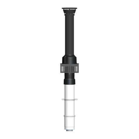
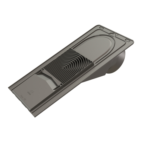
ubbink Rolux User manual

INSTALLATION INSTRUCTIONS ENGLISHUbbink
Rolux® Vent System
ubbink
The installation instructions should be kept
with the appliance for maintenance
Ubbink bv
P.O. Box 26
6980 AA Doesburg
The Netherlands
T +31 313 48 02 00
F +31 313 47 39 42
www.ubbink.nl
article code: 0072288 07/08
version 1.0

Contents
Introduction 3
Installation Requirements
Approvals/codes 4
Do not use with other vent products 4
Inspection 4
Condensate 4
Recommended venting air intake terminal position 5
General Installation Instructions
Joint connection 6
Coping with condensation 6
Appliance connection (male top) 6
Appliance connection (female top) 7
Condensate drain 7
Shortening of vent extensions 7
Parts & Dimensions 8
Installation Instructions Horizontal Discharge Vent System
Identify the vent location 10
Measure dimension to fit 10
Final installation of the vent system 11
Installation examples 12
Installation Instructions Vertical Discharge Vent System
Identify the vent location 13
Cut to fit 13
Mounting the vent system 14
Installation examples 15
2

3
The Ubbink Rolux® concentric vent system is considered part of the direct vent tankless
water heater.
The Ubbink Rolux® concentric vent system was tested and approved with the appliance
by a third party testing agency. Check the manufacturer's installation instructions or
certificate of compliance to confirm that the Ubbink Rolux® concentric vent system is
approved for your direct vent tankless water heater.
The tankless water heater installation instructions take precedence over this document.
Always refer to the appliance installation instructions before proceeding with the
installation of this product.
Introduction
Improper installation of vent system and components, or failure to
follow all installation instructions, can result in property damage
or serious injury.
WARNING

4
Installation and service of Ubbink Rolux® concentric vent systems must be performed
by a qualified installer, service agency or the gas supplier.
Approvals/codes
The installation must conform with local codes or, in the absense of local codes, the
National Fuel Gas Code, ANSI Z223.1/NFPA 54 and/or CSA B149.1, Natural Gas and
Propane Installation Code.
The maximum vent length, as stated in the water heater installation instructions and
these instructions, should never be exceeded.
Do not use with other vent products
Ubbink Rolux® vent systems must be used throughout the entire vent system.
Do not use vent components from other vent manufacturers when using the Ubbink
Rolux® vent system.
Unless approved by the appliance manufacturer, do not connect this Ubbink concentric
vent into a common vent system.
Inspection
Before installation inspect each vent component for damage and correct seal
placement. Do not attempt to fix or install any damaged vent components.
Condensate
Vertical Termination Installations
• A condensate collector MUST be used on all vertical termination installations.
Horizontal Termination Installations
• A condensate collector MUST be installed on the vent system for any horizontal
termination with a total vertical rise greater than 5 feet.
• Slope horizontal venting 1/4 inch per foot either toward the appliance with a
condensate collector or toward the exhaust terminal (Ubbink prefers pitching the
vent 1/4 inch per foot towards the appliance with a condensate collector).
• If a condensate collector is NOT used for horizontal terminations, it is permitted to
pitch the vent 1/4 inch per foot toward the termination under the following
conditions:
1. The vent system should be inspected annually for signs of damage or condensate
leaks. If the vent system appears damaged the appliance must be turned off and
the vent system repaired.
2. The horizontal termination may not be located above a public walkway, driveway
or area where condensate or vapor could create nuisance or hazard.
3. Ice can develop in regions of cold climate. A 1/4 inch per foot pitch to the
appliance with the use of the condensate collector is recommended (Ubbink can
not be held liable for personal injury or property damage due to ice formation)
Before installation, be sure to identify the appliance top is a male connection or female
connection with integrated condensate collector.
Installation Requirements

5
Recommended vent/air intake terminal position
A Clearance above grade, veranda, porch, deck, or balcony 1 foot 1 foot (0,30 m)
B Clearance to window or door that may be opened 1 foot 3 feet (0,91 m)
C Clearance to permanently closed window * *
D Vertical clearance to ventilated soffit, eaves or overhang **
E Clearance to unventilated soffit, eaves, or overhang * *
F Clearance to outside corner * *
G Clearance to inside corner * *
HClearance to each side of center line extended above
meter/regulator assembly *
3 feet (0,91 m) within a
height 15 feet (4,57 m)
above the meter/regulator
assembly
I Clearance to service regulator vent outlet *
JClearance to nonmechanical air supply inlet to building or the
combustion air inlet to any other appliance 1 foot
K Clearance to a forced air inlet into a building
3 feet above if
within 10 feet
horizontally
LClearance above paved sidewalk or paved driveway located on
public property *
MClearance under deck, veranda, porch, or balcony (open on 3
sides)
* For clearances not specified in ANSI Z223.1 / NFPA 54 or CGA-B149, please use clearances in accordance with
local installation codes and the re
q
uirements of the
g
as su
pp
lier.
REF DESCRIPTION U.S.
Installations Canadian
Installations
*
OPERABLE
OPERABLE
FIXED
CLOSED
FIXED
CLOSED
DETAIL
INSIDE CORNER
VE TERM PERMITTE
V
V
V
V
V
V
V
V
X
X
V
VVENT TERMINAL PERMITTED AREA WHERE TERMINAL IS NOT PERMITTED AIR SUPPLY INLET
B
B
BA
J
BIM
C
F
B
B
E
D
L
G
A
H
K
Maintain 12” of clearance above the highest anticipated snow level or grade or whichever is greater.
Please refer to your local codes for the snow level in your area.
CAUTION
1 foot (0,30 m)
3 feet (0,91 m)
3 feet (0,91 m)
6 feet (1,83 m)
7 feet (2,13 m)
Terminals should be so positioned as to avoid products of combustion
entering openings into buildings or other flues or vents

General Installation Instructions
Joint connection
Coping with condensation
Appliance connection (male appliance top)
Appliance connection (female appliance top)
Vent connections must be firmly pressed together so that the gaskets form
an airtight seal. To complete the joint connection, secure with three #8x1/2" sheet metal
screws. Secure the vent to the wall or ceiling with pipe clamps or perforated hanger iron.
Vent lengths greater than 5ft. should pitch a minimum 1/4"/ft. (1°) to the appliance.
Note: see exception under Condensate on page 4.
For a male appliance top, the first vent component to the appliance must be a vertical
discharge adapter or a horizontal discharge adapter. Never use a vent extension as the first
component to a male appliance top.
Installations with a female appliance top do
not need an appliance adapter or a
condensate collector. Simply insert the male
end of a vent component into the female
appliance top and use the integrated
condensate collector.
6

0.4 inch (10 mm)
y
y + 0.4" (y + 10 mm)
y
white
(outer)
aluminum
(inner)
X + 2.5" (X + 65 mm)
0.4" (10 mm)
X 1.25"1.25"
Shortening of vent extensions
Condensate drain
The aluminum inside pipe should always extend 0.4” (10 mm) beyond the white outside
pipe on the male end of the vent extension.
Always cut the male end of the vent pipe extension. Do not attempt to cut the
female end.
Pipes overlap by 1.25” (37 mm). Therefore when cutting
to size, add 2 x 1.25 = 2.5” (65 mm) to the extension pipe
length (X) needed for installation.
Deburr the sharp edges, other wise the gaskets might
get damaged, which can result in the system no longer
being air tight.
Improper installation of vent system and components, or failure to
follow all installation instructions, can result in property damage
or serious injury.
7
A
B
D
C
B
D
C
male
appliance top
female
appliance top
Condensate can damage
the water heater, please
read carefully page 4 in
this installation manual.
To prevent condensate from draining back to the appliance, a condensate collector (B)
and trap (C) should be used. The trap must maintain 3" of fluid and the drain tube must
pitch down from the appliance. Annually inspect the collector and trap for obstructions
and fluid content in the trap. Drain and dispose of condensate per local codes.
Female Appliance Top: The female appliance connection has an integrated condensate
collector. When using this condensate collector remove the drain cap and install a
condensate trap per the installation instructions.
Male Appliance Top: Install a condensate collector and trap as close as possible to the
appliance.
WARNING

4.9" (124 mm)
adjustable length
Horizontal Termination
8
for all Rolux®vent system components
Parts & Dimensions

vertical discharge roof terminal pitch roof flashing
flat roof flashing Flashing for Metal Roof wall-thimble
10 11
12 14
Water Heater Guard
15
18
bugguard
17
Pass Through Plate
16
condensate trap kit
13 Outdoor Vent Extension Cover
19
9

D= 5.5" (140 mm)
Cover the top of the heater
to prevent debris from
entering when cutting
NOTE
D= 5.5" (140 mm)
10
Installation Instructions
Rolux®Horizontal Discharge Vent System
1
2
Steps:
Case A: Place the horizontal Discharge Adapter on the appliance.
Case B: Place the 90° Vent Pipe Elbow on the appliance.
- Mark position on wall
- Or use template provided with water heater
- Cut hole, covering the top of the water heater to prevent debris from entering
Identify the vent location
Measure dimension to fit
Reference page 4 of these installation
instructions for the acceptable pitch direction.
CASE A:
Installation with Male Appliance Top
Case B:
Installation With Female Appliance Top
White Outer Pipe
Metal Inner Pipe

First place innerwall plate to
slide terminal through
NOTE
3
After cutting the appropriate length, slide the Horizontal Termination through
the hole in the wall. Position the first rubber wall plate around the male end
of the termination.
Case A; Slide the male end of the termination in the Horizontal Discharge Adapter.
Case B: Slide the male end of the termination into the 90° Vent Pipe Elbow.
Fill the gaps between the wall and the vent pipe penetration with a weather proof
Sealant. Finally, position the second rubber wall plate around the vent pipe, between
The end of the termination and the exterior wall.
Final installation of the vent system
Condensate can damage the water heater, please read carefully
page 4 in this installation manual
11
NOTE
CASE A:
Installation with Male Appliance Top
Case B:
Installation With Female Appliance Top

3
4
3
4
13
8
7
1
5
condensate direction
Female
appliance
top
13
3
7
4
5
condensate direction
Female
appliance
top
3
4
13
8
7
1
5
condensate direction
Male
appliance
top
Horizontal Vent System
Installation examples
12
min. 1˚
(= 0.25 inch/ft)
(= 19 mm/m)
min. 1˚
(= 0.25 inch/ft)
(= 19 mm/m)

Cover the top of the heater
to pr
event debris fromentering
.
NOTE
A
B
B
C
X
X
Installation Instructions
Rolux® Vertical Discharge Vent System
1
2
Determine the location where the roof discharge terminal will be installed. Taking into
account the angle of the roof, cut the hole with a dimension that allows the vertical
discharge roof terminal to be installed (6"x6" hole for flat roof, 9"x6" hole for 12/12
pitch, or 12"x6" hole for 16/12 pitch).
The terminal can be shortened by
removing the components A+B+C,
and then shortening both the inside
and outside pipes with the same
length X.
Re-assemble the terminal by attaching
the components A, B, and C in the
correct order. Tighten component B
securely.
Identify the vent location
Cut to fit
13

3
Vent connections must be firmly pressed together so that the gaskets form an airtight
seal. Secure the system with the supplied vent pipe clamp or perforated hanger iron.
Mounting the vent system
Condensate can damage the water heater, please read carefully
page 4 in this installation manual
14
NOTE

10
5
7
11
7
12
13
13
13
8
2
6
6
5
5
5
10
10
11
Female
appliance
top
Female
appliance
top
Male
appliance
top
Vertical Vent System
Installation examples
15
Other manuals for Rolux
2
Table of contents
Other ubbink Fan manuals
Popular Fan manuals by other brands

Webasto
Webasto BlueCool F Series operating instructions

LU-VE
LU-VE ALFA Arctigo IS instruction manual

Ruck Ventilatoren
Ruck Ventilatoren MRS 225 E2 21 Series Assembly instruction

Beacon Lighting
Beacon Lighting Lucci Connect 299041 instructions

Datex-Ohmeda
Datex-Ohmeda Aestiva 7900 SmartVent Service manual

Excel
Excel 52-AGT manual