ubbink Rolux User manual

1
Installation instructions \ Instrucciones de
instalación
0072XXX XX/XX version 1.0
Ubbink bv
Verhuellweg 9
NL – 6984 AA Doesburg
T + 31 (0) 313 480 200
F + 31 (0) 313 473 942
rolux@ubbink.nl
www.ubbink.nl
Rolux®Vent System
The installation instructions should be kept with the appliance for maintenance.
Sistema de ventilación Rolux®
Las instrucciones de instalación deben guardarse con el aparato para su mantenimiento.
US
p. 1/16
ES
p . 17/32
FRolux®Vent system
Pour une traduction complète du manuel en français, vous pouvez le télécharger du site Web
de www.rinnai.us.
WARNING
Improper installation of vent system and components, or failure to follow
all installation instructions, can result in property damage or serious injury.

2
ES
US Contents
Introduction 2
Installation Requirements 3
Approvals/codes 3
Do not use with other vent products 3
Inspection 3
Condensate 3
Recommended venting air intake terminal position 4
General Installation Instructions 5
Joint connection 5
Coping with condensation 5
Appliance connection (female top) 5
Condensate drain 5
Shortening of vent extensions 6
Installation Instructions Horizontal Discharge Vent System 6
Identify the vent location 6
Measure dimension to fit 7
Final installation of the vent system 7
Installation Instructions Vertical Discharge Vent System 8
Identify the vent location 8
Cut to fit 8
Mounting the vent system 9
Installation Instructions Raised Horizontal Discharge Vent System 10
Kit contents 10
Incorrect installation location 10
Correct installation location 11
Identify the vent location 11
Measure dimension to fit 12
Installation of raised horizontal cover 12
Parts & dimentions 13
Horizontal Discharge Vent System Installation Examples 14
Vertical Discharge Vent System Installation Examples 15
Instrucciones de instalación 17
Introduction
The Ubbink Rolux® concentric vent system is considered part of the direct vent
tankless water heater.
The Ubbink Rolux® concentric vent system was tested and approved with the appliance
by a third party testing agency. Check the manufacturer’s installation instructions or
certificate of compliance to confirm that the Ubbink Rolux® concentric vent system is
approved for your direct vent tankless water heater.
The tankless water heater installation instructions take precedence over this document.
Always refer to the appliance installation instructions before proceeding with the
installation of this product.

3
Installation Requirements
Installation and service of Ubbink Rolux® concentric vent systems must be
performed by a qualified installer, service agency or the gas supplier.
Approvals/codes
The installation must conform with local codes or, in the absense of local codes,
the National Fuel Gas Code, ANSI Z223.1/NFPA 54 and/or CSA B149.1, Natural Gas
and Propane Installation Code.
The maximum vent length, as stated in the water heater installation instructions
and these instructions, should never be exceeded.
Do not use with other vent products
Ubbink Rolux® vent systems must be used throughout the entire vent system.
Do not use vent components from other vent manufacturers when using the
Ubbink Rolux® vent system.
Unless approved by the appliance manufacturer, do not connect this
Ubbink concentric vent into a common vent system.
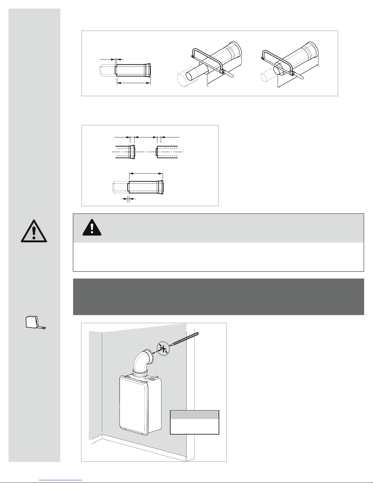
Inspection
Before installation inspect each vent component for damage and correct seal
placement. Do not attempt to fix or install any damaged vent components.
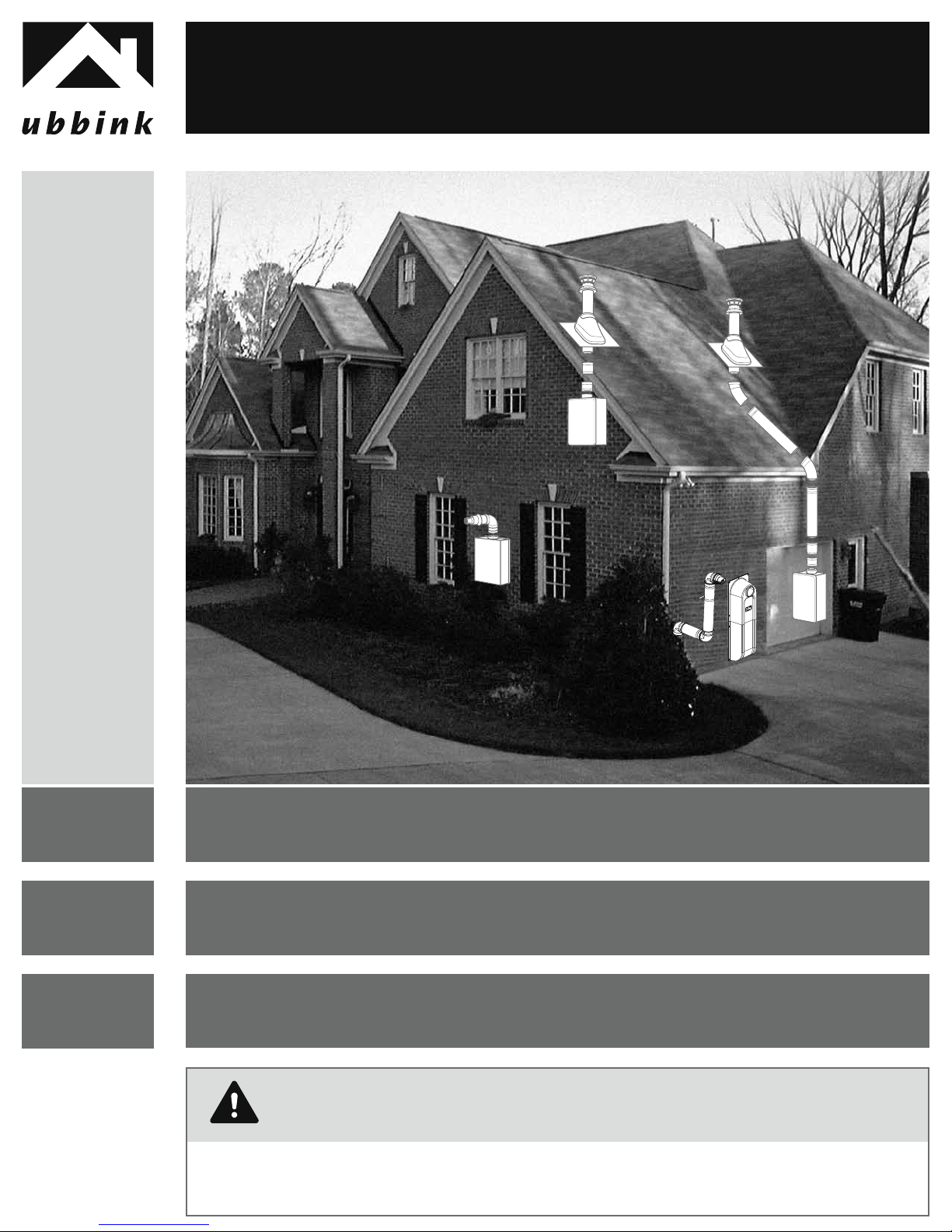
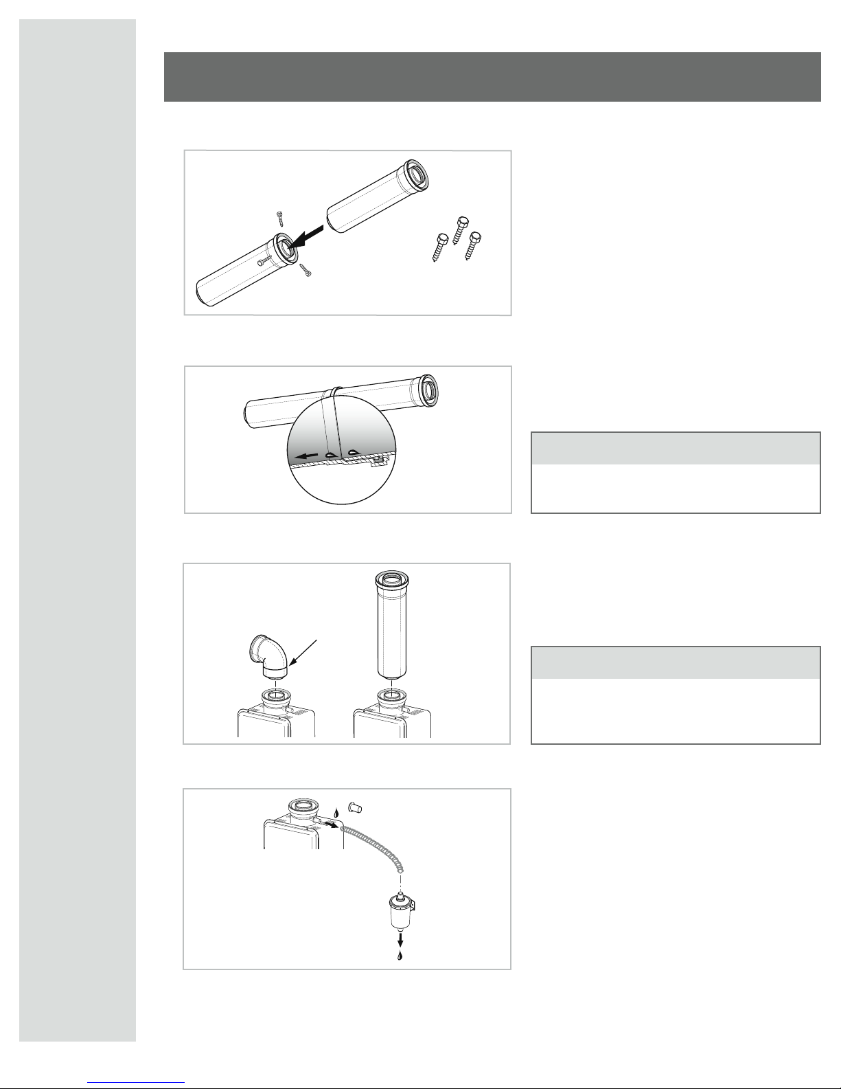
Condensate
Vertical Termination Installations
- A condensate collector MUST be used on all vertical termination installations.
Horizontal Termination Installations
- A condensate collector MUST be installed on the vent system for any horizontal
termination with a total vertical rise greater than 5 feet. (1,5 m)
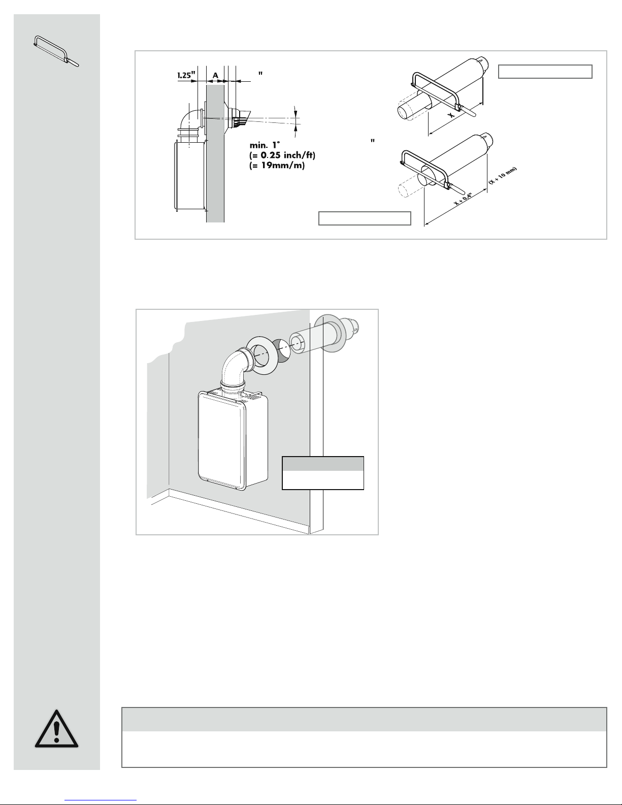
- Slope horizontal venting 1/4 inch per foot (25 mm/m) either toward the appliance with a
condensate collector or toward the exhaust terminal (Ubbink prefers pitching the vent
1/4 inch per foot (25mm/m) towards the appliance with a condensate collector).
- If a condensate collector is NOT used for horizontal terminations, it is permitted to pitch
the vent 1/4 inch per foot (25 mm/m) toward the termination under the following
conditions:
1. The vent system should be inspected annually for signs of damage or
condensate leaks. If the vent system appears damaged the appliance must be turned
off and the vent system repaired.
2. The horizontal termination may not be located above a public walkway,
driveway or area where condensate or vapor could create nuisance or hazard.
3. Ice can develop in regions of cold climate. A 1/4 inch per foot pitch to the
appliance with the use of the condensate collector is recommended (Ubbink can
not be held liable for personal injury or property damage due to ice formation).
Before installation, be sure to identify the appliance top is a male connection or
female connection with integrated condensate collector.

4
OPERABLE
OPERABLE
FIXED
CLOSED
FIXED
CLOSED
DETAIL
INSIDE CORNER
V
V
V
V
V
V
V
V
X
X
V
VENT TERMINAL PERMITTED
VAREA WHERE TERNIMAL IS NOT PERMITTED
AIR SUPPLY INLET
B
B
BA
J
BIM
C
F
B
B
E
D
L
G
A
H
K
* For clearances not specified in ANSI Z223.1 / NFPA 54 or CGA-B149, please use clearances in accordance with
local installation codes and the requirements of the gas supplier.
CAUTION
Maintain 12” of clearance above the highest anticipated snow level or grade or whichever is greater.
Please refer to your local codes for the snow level in your area.
REF
A
B
C
D
E
F
G
H
I
J
K
L
M
DESCRIPTION
Clearance above grade, veranda, porch, deck, or balcony
Clearance to window or door that may be opened
Clearance to permanently closed window
Vertical clearance to ventilated soffit, eaves or overhang
Clearance to unventilated soffit, eaves, or overhang
Clearance to outside corner
Clearance to inside corner
Clearance to each side of center line extended above
meter/regulator assembly
Clearance to service regulator vent outlet
Clearance to nonmechanical air supply inlet to building
or the combustion air inlet to any other appliance
Clearance to a forced air inlet into a building
Clearance above paved sidewalk or paved driveway
located onpublic property
Clearance under deck, veranda, porch, or balcony
(open on 3 sides)
U.S.
INSTALLATIONS
1 foot
1 foot
*
*
*
*
*
*
*
1 foot
3 feet above if
within 10 feet
horizontally
*
*
CANADIAN
INSTALLATIONS
1 foot (0,30 m)
3 feet (0,91 m)
*
*
*
*
*
3 feet (0,91 m) within a height 15 feet
(4,57 m) above the meter/regulator
assembly
3 feet (0,91 m)
3 feet (0,91 m)
6 feet (1,83 m)
7 feet (2,13 m)
1 foot (0,30 m)
Recommended vent/air intake
terminal position
Terminals should be so positioned as to avoid products of combustion entering openings
into buildings or other flues or vents. The Ubbink Rolux White Vent extension material is
primarily designed for indoor use. If used outdoors the material should be protected for
UV-radiation (direct sunlight).

5
General Installation Instructions
Joint connection
Vent connections must be firmly pressed
together so that the gaskets form an
airtight seal. To ensure optimum joint con-
nection, it is recommended to secure with
three #8x1/2” self tapping screws. Secure
the vent to the wall or ceiling with pipe
clamps or perforated hanger iron.
Vent connections extending beyond the
outside of a building or structure should
be enclosed to protect seals and gaskets.
Coping with condensation
Horizontal vent lengths greater than 5ft.
(1,5m) should pitch a minimum 1/4”/ft.
(25mm/m) or (1°) to the appliance.
Appliance connection (female appliance top)
Installations with a female appliance top
do not need an appliance adapter. Simply
insert the male end of a vent component
into the female appliance top.
Condensate drain
Condensate can damage the water
heater, please read carefully page 3
in this installation manual.
To prevent condensate from draining
back to the appliance, a condensate
collector (B) and trap (C) should be
used. The trap must maintain 3” (75 mm)
of fluid and the drain tube must pitch
down from the appliance.
Annually inspect the collector and trap for obstructions and fluid content in the trap.
Drain and dispose of condensate per local codes.
Remove the drain cap and install a condensate trap per the installation instructions.
x
NOTE
for Rinnai appliances with male appliance
top we refer to the Web-site www.rinnai.us
for specific installations instructions.
NOTE
See exception under Condensate on
page 3.
B
D
C

6
WARNING
Improper installation of vent system and components, or failure to follow
all installation instructions, can result in property damage or serious injury.
Shortening of vent extensions
The aluminum inside pipe should always extend 0.4” (10 mm) beyond the white outside
pipe on the male end of the vent extension.
Always cut the male end of the vent pipe extension. Do not attempt to cut the female end.
Pipes overlap by 1.25” (37 mm). Therefore
when cutting to size, add 2 x 1.25 = 2.5”
(65 mm) to the extension pipe length (X)
needed for installation.
Deburr the sharp edges, other wise the
gaskets might get damaged, which can
result in the system no longer being air
tight.
0.4 inch (10 mm)
X + 2.5" (X + 65 mm)
0.4" (10 mm)
X 1.25"1.25"
y
y + 0.4" (y + 10 mm)
y
white
(outer)
aluminum
(inner)
0.4 inch (10 mm)
X + 2.5" (X + 65 mm)
0.4" (10 mm)
X 1.25"1.25"
y
y + 0.4" (y + 10 mm)
y
white
(outer)
aluminum
(inner)
1
Installation Instructions
Rolux®Horizontal Discharge Vent System
Identify the vent location
Steps:
- Place the 90° Vent Pipe Elbow on the
appliance.
- Mark position on wall
- Or use template provided with water heater
- Cut hole, covering the top of the water
heater to prevent debris from entering
Cover the top of the heater
to prevent debris from
entering when cutting
NOTE
D = 5.5" (140 mm)

7
2(30 mm)
1.15 (30 mm)
x = A + 2.5 (65 mm) minimum
(whiter outer)
White Outer Pipe
Metal Inner Pipe
Reference page 4 of these installation instructions for the acceptable pitch direction.
Final installation of the vent system
- After cutting the appropriate length
slide the horizontal through the hole
in the wall. Position the first rubber
wall plate around the male end of the
termination.
- Slide the male end of the termination
in the Horizontal Discharge Adapter.
- Fill the gaps between the wall and the
vent pipe penetration with a weather
proof Sealant.
- Finally, position the second rubber
wall plate around the vent pipe, between
the termination and the exterior wall.
First place innerwall plate to
slide terminal through
NOTE
3
NOTE
Condensate can damage the water heater, please read carefully page 3 in
this installation manual.
Measure dimension to fit

8
1
2
Installation Instructions
Rolux®Vertical Discharge Vent System
Identify the vent location
Determine the location where the roof dis-
charge terminal will be installed. Taking into
account the angle of the roof, cut the hole
with a dimension that allows the
vertical discharge roof terminal to be
installed
- 6”x6” 150x150 mm hole for flat roof,
- 9”x6” 225x150 mm hole for 12/12 pitch (45°)
- 12”x6” 300x150 mm hole for 16/12 pitch
(55°).
Cut to fit
The terminal can be
shortened by cutting
both the inside and
outside pipes with
the same length X.
Cover the top of the heater
to pr
event debris from entering
.
NOTE
X
X
A
B

9
3
Installation Instructions
Mounting the vent system
Vent connections must be firmly pressed
together so that the gaskets form an airtight
seal. Secure the system with the supplied
vent pipe clamp or perforated hanger iron.
NOTE
Condensate can damage the water heater, please read carefully page 3 in
this installation manual.

10
Description qt
A 90* elbow 2
B 14.2" (360 mm) vent extension 1
C 30" (750 mm) vent extension 1
D Vent pipe clamp 1
E Horizontal termination 1
F Enclosure 1
Screws/Anchors 9
3pc. #8x1/2" screws 4
A
A
A
B
C
D
EF
Installation Instructions
Ubbink Rolux® concentric vent system Raised Horizontal
Termination Kit
Incorrect installation Location
Note:
Do not bury the enclosure
below Grade
Note:
Do not position the enclosure
below Grade

11
Min.2”
Above Grade
Installation of the Raised Horizontal
Termination Kit
Correct Installation Location
Note: Refer to the illustration below and the information on page 4 for correct vent
and termination locations.
Identify the vent location
- Mount and install the appliance as
indicated in the water heater instructions.
- Mark position on wall or use template
provided with the water heater
- Take into account the minimum distance
(2 inches or 50 mm) above grade for the
wall passage.
- Cut hole 5.5“ (140 mm) diameter, covering
top of the appliance to prevent debris
from entering.
B
2” (50 mm) minimum
5,5” (140 mm)

12
Measure dimension to fit
- Using the instruction on page 6 cut the vent piece B, to the appropriate length.
Note: the outer edge of the extension Ashould be cut so that it protrudes max. 0.5inch (10 mm)
through the outside of the wall.
- Slide the cut vent extension through the wall and
assemble it to the 90° elbow.
- Next install the 90° vent elbow, vent extension, and finally
the 90° vent elbow attached to the discharge terminal.
- Secure the vent assembly to the wall with the provided
pipe clamp.
- Seal the wall penetration with water proof silicon
sealant to prevent moisture from entering the structure.
The sockets can be secured with the supplied (#8x1/2”)
sheet metal screws.
clamp
sealant
A
10 mm
Installation of the raised horizontal cover
- Position the hole at the top of the enclosure over
the vent termination, slide the cover to the wall.
- The cover should be positioned in a vertical
position.
- If needed water-proof silicon sealant can be
used to seal the ridge at the top of the cover.
- Assemble the cover to the wall with provided
screws and wall anchors (optional) depending on
wallstructure.
- The screw positions are clearly marked on the cover.
If needed the cover can be cut in the middle and slid
together to reduce the overall length of the cover.
Note: Do not position any part of the cover or
vent system below grade.

13
Parts & Dimensions
For all Rolux®vent system components
vertical discharge roof terminal
8
pitch roof flashing
9
flat roof flashing10 wall-thimble
12
water heater guard
13 pass through plate
14 bugguard
15
flashing for metal roof
16 outdoor vent extension cover
17
condensate trap kit
11
7
12
3
4
5
6

14
Horizontal Vent System
Installation examples
condensate direction
1
2
11
3
5
3
con
d
ensate
d
irection
11
1
5
2
3
condensate direction
11
condensate direction
5
5
5
3
17
3
7
1
min. 1˚
(= 0.25 inch/ft)
(= 19 mm/m)
min. 1˚
(= 0.25 inch/ft)
(= 19 mm/m)
min. 1˚
(= 0.25 inch/ft)
(= 19 mm/m)
min. 1˚
(= 0.25 inch/ft)
(= 19 mm/m)

15
Vertical Vent System
Installation examples
11
8
3
5
9
5
10
11
11
4
4
3
3
3
8
8
9

16
Other manuals for Rolux
2
Table of contents
Other ubbink Fan manuals
Popular Fan manuals by other brands

Ventry
Ventry 20EM3550 owner's manual

Vortice
Vortice C ATEX Instruction booklet

Fantech
Fantech PBH4 Installation, operation and maintenance manual

Honeywell
Honeywell ELSTON manual

Parrot Uncle
Parrot Uncle F6237110 Installation & operating instructions

Climate RENTAL SOLUTIONS
Climate RENTAL SOLUTIONS AM103 instruction manual