UCHIDA AeroCut nano+ User manual

SERVICE MANUAL
UCHIDAYOKO CO., LTD., TOKYO, JAPAN
V2.00

AeroCut nano+ SERVICE MANUAL
2
Contents
1. Installation......................................................................................................4
2. General instruction.........................................................................................6
3. Touch panel operation....................................................................................9
3- (1) MANUAL CONTROL screen................................................................9
3- (2) Maintenance screen............................................................................9
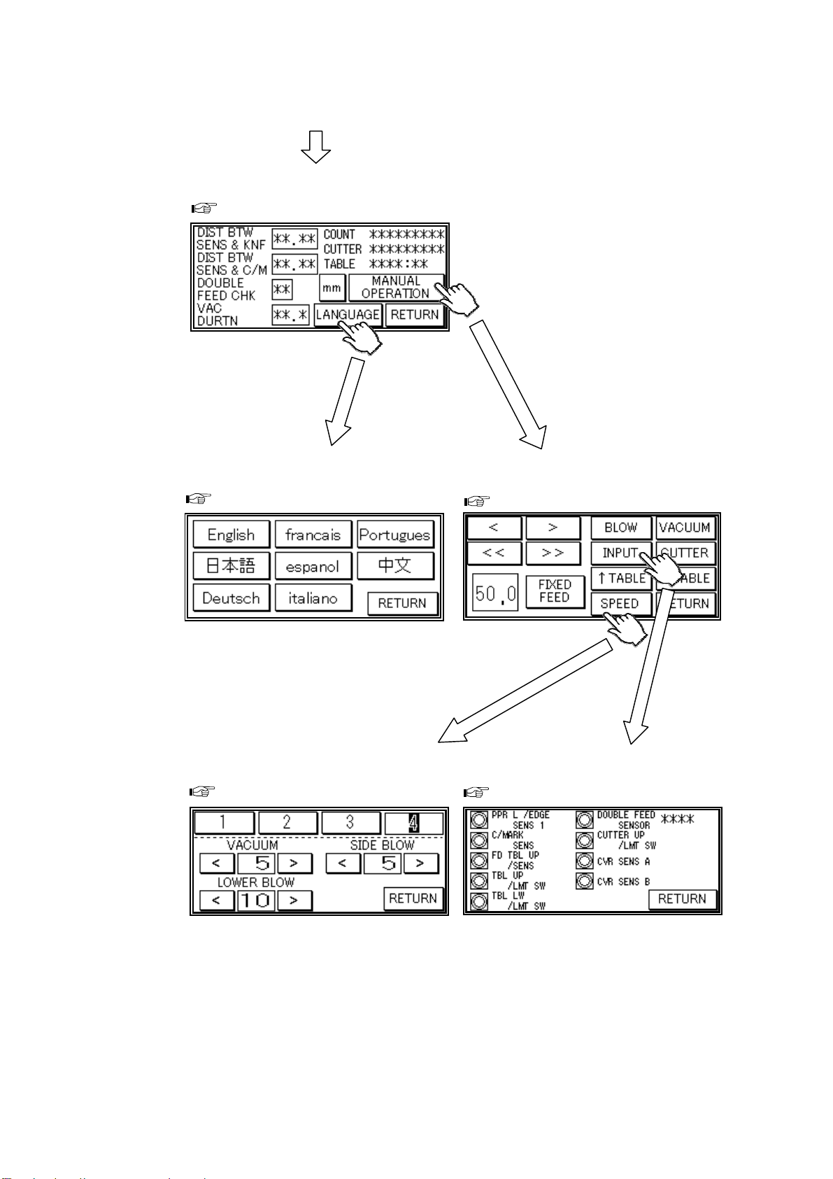
3- (3) SERVICE MENU screen ....................................................................11
3- (4) MANUAL OPERATION screen...........................................................11
3- (5) SPEED screen .................................................................................. 12
3- (6) INPUT DATA CHECK screen.............................................................12
3- (7) LANGUAGE screen...........................................................................12
4. Paper jam.....................................................................................................13
5. Replacement of parts ...................................................................................15
5- (1) Guillotine ...........................................................................................15
5- (2) Slitter.................................................................................................16
5- (3) Feed belt Unit....................................................................................17
6. Adjustment.................................................................................................... 18
6- (1) Feed sensor position.........................................................................18
6- (2) Double feed sensor adjustment......................................................... 26
6- (3) Sensitivity of Cutmark sensor............................................................27
6- (4) Guillotine angle.................................................................................. 28
6- (5) Cutting location (Guillotine) ............................................................... 28
6- (8) PCB (CPU board) setting .................................................................. 30
7. Program update............................................................................................31
7- (1) Outline............................................................................................... 31
7- (2) Connecting software install................................................................ 32
7- (3) Touch panel update...........................................................................39
7- (4) PCB (CPU board) update..................................................................42
8. Cleaning & greasing.....................................................................................48
9. Recommended replacement parts................................................................49
10. Error messages..........................................................................................50
11. Troubleshooting..........................................................................................53
12. Drawing...................................................................................................... 55
12- (1) Drawing........................................................................................... 55
12- (2) Board Details................................................................................... 57
12- (3) Input/Output LED Details................................................................. 59
12- (4) Tap Voltage Details.......................................................................... 60

AeroCut nano+ SERVICE MANUAL
3
Record of change
No. Date Contents of change Expected date
to change

AeroCut nano+ SERVICE MANUAL
4
1. Installation
(a) Caster (b) Feed table
Please be sure to lock a caster
brake.
(C) Stacker and Waste box
Unlock
Lock
Feed table
Hex key
Bolts x3
M4x8
Long stacker
Waste box
Card stacker
Stacker end
Business card
partition

AeroCut nano+ SERVICE MANUAL
5
Bolts
(d) Electric-power
(e) In case of tabletop use
①Remove the bottom frame connecting bolts.
②Put the machine on a table not to cover the waste chute.
Bottom frame
A
C 100-240V
50/60Hz
100W
Electric power
cord
Lock
Waste chute

AeroCut nano+ SERVICE MANUAL
6
Slitter blades
High voltage
Guillotine blades
Timing belts
2. General instruction
(a) Caution
(b) Necessary tools
・C-clipringpliers ・Maintenance kit
(c) Factory setting
Factory setting sheet is attached inside of the
front cover.
To replace slitter blades
Program update tool
Pipe
(For slitters)
To replace slitter blades

AeroCut nano+ SERVICE MANUAL
7
Disconnect the connector fo
r
the touch panel.
Touch panel
Slope
Sensor cover
(d) Remove covers

AeroCut nano+ SERVICE MANUAL
8
(e) Names of parts
Slitter head
Side fan motor (Blow)
Friction pulley Eject roller
Touch panel
Inlet
&
Fuse
Power switch
DC power supply
PCB (CPU board)
Feed table motor
Fan motor (Suction)
Fan motor (Blow)
Feed sensor
Feed belts
Guillotine
(Cutter)
Guillotine motor
Micro switch
(Feed table lower limit)
Micro switch
(Cover open)
Main motor
Guillotine switch
Timing belt
Feed table stay
Carrying roller
Cutmark sensor
Origin sensor Double feed sensor
Feed motor

AeroCut nano+ SERVICE MANUAL
9
3. Touch panel operation
3- (1) MANUAL CONTROL screen
3- (2) Maintenance screen
Press ①and ②(buttons are not
shown ) one by one to ente
r
password entry mode.
Enter the service password.
Home screen
Operation manual
5.1 Manual control screen
MANUAL CONTROL screen
Home screen
Press ③once.
(A button is not shown.)
①
②
MANUSET screen
③

AeroCut nano+ SERVICE MANUAL
10
SERVICE MENU screen
Page 11
LANGUAGE screen
Page 12 MANUAL OPERATION screen
Page 11
SPEED screen
Page 12 INPUT DATA CHECK screen
Page 12

AeroCut nano+ SERVICE MANUAL
11
3- (3) SERVICE MENU screen
①Distance between origin sensor and guillotine. [mm]
②Distance between origin sensor and Cutmark sensor. [mm]
③The number of times that the machine checks double-feed. [times]
④Paper vacuuming time when the feed table is lifted to the upper limit. [sec]
⑤Total number of processed paper. [sheets]
⑥Total number of processed Guillotine. [times]
⑦Operation time of Feed table. [hours : minutes]
⑧Go to MANUAL OPERATION screen
⑨Go to LANGUAGE screen
⑩This is to set either mm or inch as the measurement input unit.
3- (4) MANUAL OPERATION screen
①Carrying roller will rotate.
②Carrying roller will rotate. (Continuous)
③Carrying rollers will rotate at input length. [mm]
④Fan motor (Blow) will be turned ON.
⑤Fan motor (Suction) will be turned ON.
⑥Go to INPUT DATA CHECK screen.
⑦Guillotine will move once.
⑧Feed table will move upward.
⑨Feed table will move downward.
⑩Go to SPEED screen.
MANUAL OPERATION screen
①
②
③
④
⑥
⑧
⑩
⑤
⑦
⑨
Not changeable
SERVICE MENU screen
①
②
③
④
⑤
⑥
⑦
⑧
⑨
⑩

AeroCut nano+ SERVICE MANUAL
12
3- (5) SPEED screen
Same as the MANUAL CONTROL screen. (Page 9 )
・In case of finishing thick paper, slow down the speed.
・If finished sizes are inaccurate or inconsistent, there is a possibility that the running
speed is too fast. Slow down the speed.
・Note. The reference of the paper thickness and speed.
-160 g/㎡4
160-280 g/㎡3
280- g/㎡2
3- (6) INPUT DATA CHECK screen
Sensor / Switch signals can be checked.
①Origin sensor
②Cutmark sensor
③Feed sensor
④- Invalid -
⑤Micro switch (Feed table lower limit)
⑥Double feed sensor
⑦Guillotine switch
⑧⑨ Micro switch (Cover open)
3- (7) LANGUAGE screen
Languages on the touch panel can be changed.
・Some languages are not selectable.
・Some languages require Passwords.
- 0.006” (0.15mm) 4
0.006” - 0.01”(0.25mm) 3
0.01” - 2
SPEED screen
LANGUAGE screen
INPUT DATA CHECK screen
①
②
③
④
⑤
⑥
⑦
⑧
⑨
On
Off
FastSlow

AeroCut nano+ SERVICE MANUAL
13
4. Paper jam
①Enter MANUAL CONTROL screen,
press < > buttons to inch the rollers
forward/backward and remove the
jammed paper.
If paper is stuck around the guillotine
section, press CUTTER to cycle the
guillotine to chop jammed paper.
②If the Main motor doesn't rotate, slow
down the speed.
The main motor has more torque as the
speed becomes slower.
③If paper is still remaining after process ①and ②, remove the slitter cover and pick up
the jammed paper.
④After removing the jammed paper, put the slitter cover and reset SPEED.
Slitter cover
Screwdriver
Screws
Length
130mm (5”)
or less
MANUAL CONTROL screen

AeroCut nano+ SERVICE MANUAL
14
Note.
If paper jam often occurs, make sure that paper strip is not left in the indicated sections.
・Inside of Slitter head
・Eject roller
Origin sensor
Carrying roller Feed belt
・The path between the feed belt to the
carrying rollers. ・Origin sensor

AeroCut nano+ SERVICE MANUAL
15
5. Replacement of parts
5- (1) Guillotine
①Check if the locating metal plate is in contact with
the cutter unit.
This will be a mark for reattachment.
②Remove cover and screws
③Remove Guillotine
Do not loosen these screws.
Locating metal plate

AeroCut nano+ SERVICE MANUAL
16
5- (2) Slitter
①
②

AeroCut nano+ SERVICE MANUAL
17
5- (3) Feed belt Unit
① Remove screws and cover.
② Disconnect the harness.
③ Feed belt unit can be removed after bolts are removed.
Cover
Connector
Feed belt unit

AeroCut nano+ SERVICE MANUAL
18
6. Adjustment
6- (1) Feed sensor position
(a) Blower
MANUAL CONTROL screen
SPEED screen
Standard Value
・Input 10 in case paper is too heavy to feed.
・There will be possibility of double feed if paper is too thin. In this case, input 5.
・Ensure that LONG BLOW is shown on the screen. There is possibility of empty feed.
Standard Value

AeroCut nano+ SERVICE MANUAL
19
(b) Aligner
① Check angle of aligner by position of a hole in below picture when attaching the feed belt
unit.
② It is factory setting if Feed belt unit is attached so that a small hole contacts a big hole.
Hole position
Status Default
(FactorySetting)―Parallel to Guide
Effectiveness of
Aligner High Low None
Guide
Hole

AeroCut nano+ SERVICE MANUAL
20
(c) Feed area mechanical adjustments
(1) Lower Blower position
A
djust the height by
loosenin
g
screws.
Note.
Do not remove screws because blower will drop.
Blower
Blower base
Friction surface
Blower base
Range of Value H
0.5~1.0mm
Table of contents
Other UCHIDA Cutter manuals