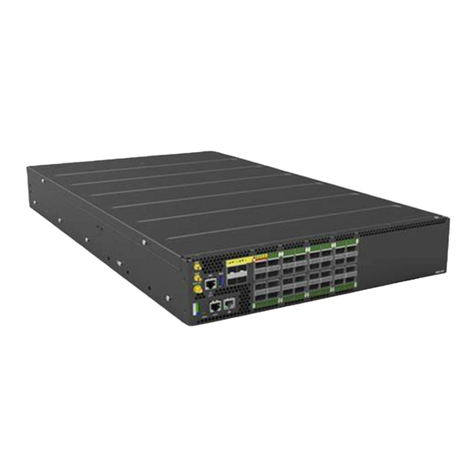
UfiSpace S9610-36D Manual

S9610-36D Hardware Installation Guide | i
Table of Contents
1Overview ........................................................................................................................1
2Preparation.....................................................................................................................2
Installation Tools......................................................................................................................2
Installation Environment Requirements..................................................................................3
Preparation Check List.............................................................................................................4
3Package Contents............................................................................................................5
Accessory List...........................................................................................................................5
Component Physical Information............................................................................................6
4Identifying Your System ..................................................................................................7
S9610-36D Overview ...............................................................................................................7
PSU Overview...........................................................................................................................7
Fan Overview ...........................................................................................................................8
Port Overview ..........................................................................................................................9
5Rack Mounting..............................................................................................................10
6Installing Fan Modules ..................................................................................................13
7Installing Power Supply Units ........................................................................................14
8Grounding the Router ...................................................................................................16
9Connecting Power .........................................................................................................18
DC Version..............................................................................................................................18
AC Version..............................................................................................................................20
10 Verifying System Operation...............................................................................................22
Front Panel LED......................................................................................................................22
PSU FRU LED ..........................................................................................................................22
Fan FRU LED...........................................................................................................................23
11 Initial System Setup...........................................................................................................24
12 Cable Connections.............................................................................................................26
Connecting the USB Extender Cable......................................................................................26
Connecting the 1PPS Interface ..............................................................................................26
Connecting the 10MHz Interface...........................................................................................27
Connecting the Transceiver...................................................................................................27
13 Cautions and Regulatory Compliance Statements ..............................................................28
Cautions and Regulatory Compliances ..................................................................................28
S9610-36D Hardware Installation Guide | 1
1Overview
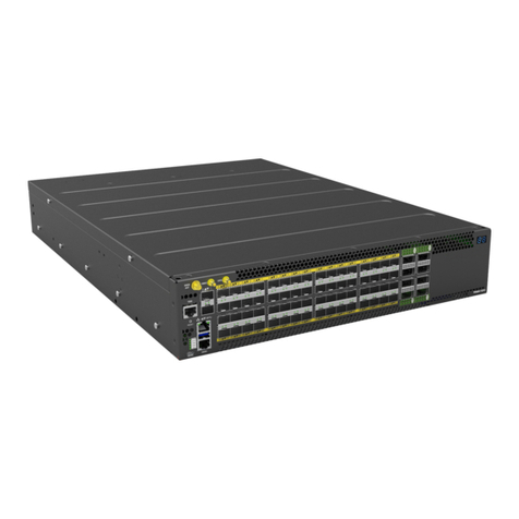
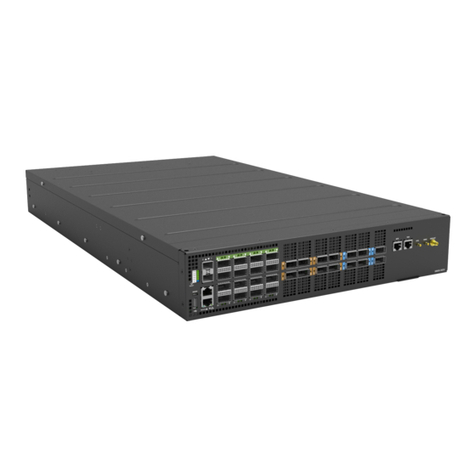
The UfiSpace S9610-36D is a 36 x 400G disaggregated open router that evolves the network
to a 400G network, which enables next generation of 5G services and applications.
The S9610-36D can be deployed at the provider edge network to enable transport services
over a scalable next generation telecom network. It is also suitable for central office data
centers and general network aggregation. With 400G supporting OpenZR+, it provides
better usage of bandwidth for metro and regional aggregation. Our S9610-36D is capable of
mobile network aggregation with support for SyncE and IEEE 1588v2 with Class C timing
accuracy.
The S9610-36D open aggregation router uses the Broadcom J2C+ silicon, which provides
16GB deep buffering and 14.4Tbps switching capacity. It includes a knowledge-based
processor (or TCAM) to perform high-performance parallel searches to reach decision
speeds of multiple billion decisions per second, which makes it ideal for provider edge
applications. As a aggregation router, the S9610-36D enables fault and performance
monitoring, non-stop routing support for control and data plane, and comprehensive high-
availability networks.
This document describes the hardware installation process for S9610-36D.

S9610-36D Hardware Installation Guide | 2
2Preparation
Installation Tools
Phillips #2 Screw Driver
4-AWG green-and-yellow wire for grounding
4-AWG DC power cable
Crimping tool
Wire stripping tool
All illustrations within this document are for reference purposes only. Actual
objects may differ.
•PC with terminal emulation software. Refer to the "Initial System Setup" section for
details.
•Baud rate: 115200 bps
•Data bits: 8
•Parity: None
•Stop bits: 1
•Flow control: None

S9610-36D Hardware Installation Guide | 3
Installation Environment Requirements
•Power Reserve: The S9610-36D power supply is available with:
1. DC Version: 1+1 Redundant and hot swappable -40 to -72V DC power supply field
replaceable unit or;
2. AC Version: 1+1 Redundant and hot swappable 200 to 240V AC power supply field
replaceable unit.
To ensure the redundant feed power design functions properly, a field with dual power
circuit is recommend with a reserve of at least 3000 watts on each power circuit.
•Space Clearance: The S9610-36D width is 17.16 inches (43.6cm) and shipped with a rack
mount brackets suitable for 19 inch (48.3cm) wide racks. The depth of the S9610-36D chassis
is 30 inches (76.2cm) without the field replaceable units (FRUs) and comes with adjustable
check mounting rails suitable for rack depths of 22 inches (55.9cm) to 33 inches (83.8cm). The
handle for the fan units will extend outwards by 1.15 inch (2.9cm) and the handle for the
power supplies will extend outwards by 1.19 inches (3cm). Therefore, to accommodate the
fan and power supply handles, a minimum space clearance of 6 inches (15.2cm) is needed at
the back of the S9610-36D. A total minimum reserve depth of 36 inches (91.4cm) is required.
Figure 1.
•
Cooling: The S9610-36D airflow direction is front-to-back. Make sure the equipment on
the same rack have the same airflow direction.

S9610-36D Hardware Installation Guide | 4
Figure 2.
Figure 3.
Preparation Check List
Task
Check
Date
Power voltage and electric current requirements
DC version: -40 to -72V DC, 80A maximum x2 or;
AC version: 200 to 240V AC, 16A maximum x2
Installation space requirements
S9610-36D requires 2RU (3.45”/8.8cm) in height, 19” (48.3cm) in
width, and need a minimum reserve depth of 36 inches (91.4cm)
Thermal requirements
S9610-36D working temperature is 0 to 45°C (32°F to 113°F), airflow
direction is front-to-back
Installation tools required
#2 Philips Screwdriver, 6-AWG yellow-and-green wire stripper, and
crimping tool
Accessories required
PC with USB ports and terminal emulation software

S9610-36D Hardware Installation Guide | 5
3Package Contents
Accessory List
Item
Description
Spec. & Dimensions
Qty.
Weight
1
Grounding Lug and
Screw Kit
1x Grounding Lugs (#4 AWG)
1.65” x 1.45” x 0.55”
(41.91 x 36.83 x 13.97mm)
2x Screws M4*L8.0mm
2x M4 Lock Washers
1 set
0.05lb (21.1g)/1 set
2
Grounding Lug
(DC Only)
4x Grounding Lugs (#4 AWG)
2.40” x 0.60” x 0.42”
(60.96 x 15.24 x 10.67mm)
1 set
0.18lb (81.48g)/1 set
3
Micro USB Cable
3.28’ (1m)
1 pcs
0.05lb (24.4g)/1 pcs
4
RJ45 to DB9 Female
Cable
8’ (2.438m)
1 pcs
0.23lb (105g)/1 pcs
5
Adjustable Mounting
Rail (for 4 post)
30.4”x 1.7” x 0.9”
(771 x 44 x 22mm)
(22”~33” rack depth)
2 sets
7.05lb (3.2kg)/2 sets
3.53lb (1.6kg)/1 set
6
Screw Kit (for Rack
Mount Bracket)
2 x Screw M4.0*L5.5
1 set
0.004lb (1.9g)/1 set
7
Power Cord
(AC Only)
72.05” (1830mm)
2 pcs
1.54lb (700g)/ 2 pcs
0.77lb (350g)/1 pcs
8
USB 3.0 Cable
7.87” (200mm)
1 pcs
0.03lb (13.6g)/ 1 pcs

S9610-36D Hardware Installation Guide | 6
Component Physical Information
Specification
Item
Description
Weight
Total package contents
92.81lb (42.1kg)
Chassis without FRU
54.01lb (24.5kg)
Power Supply Unit (PSU)
DC PSU: 4.24lb (1.9kg)
AC PSU: 4.60lb (2.1kg)
Fan module
1.63lb (737g)
Ground lug
0.05lb (21.1g)
Adjustable mounting rail
3.53lb (1.6kg)
Micro USB cable
0.05lb (24.4g)
RJ45 to DB9 female cable
0.23lb (105g)
AC power cord (AC version only)
0.7lb (318g)
USB 3.0 cable
0.03lb (13.6g)
Dimension
S9610-36D (W x D x H)
17.16” x 30” x 3.45”
(436 x 762 x 87.7mm)
PSU (W x D x H)
2.68” x 18.06” x 1.60” (68 x 458.8 x 40.6mm)
Fan (W x D x H)
3.19” x 5.96” x 3.21” (81 x 151.3 x 81.5mm)

S9610-36D Hardware Installation Guide | 7
4Identifying Your System
S9610-36D Overview
Figure 4.
PSU Overview
Power supply unit (PSU) with 1+1 Redundancy. Hot swappable, field replaceable unit (FRU).
AC Version:
Figure 5.

S9610-36D Hardware Installation Guide | 8
DC Version:
Figure 6.
Fan Overview
3+1 Redundant, hot swappable, field replaceable unit (FRU).
Figure 7.

S9610-36D Hardware Installation Guide | 9
Port Overview
Port ID
Form Factor
Maximum Support Distance
Support Speed
0~35
QSFP-DD
Up to 372.82mi (600km)
40/100/400G
The S9610-36D ports 0-35 (labelled in blue in figure below) will all function normally when
statistics counter is not enabled. Once the statistics counter is enabled, the service ports 1,
17, 19 and 35 (labelled in yellow in figure below) will be disabled and reserved for statistics
functionality. Therefore, when statistics counter is enabled, there will only be 32 service
ports available.
Figure 8.
The S9610-36D has the following 400G ports with the power capacity to support OpenZR+
and 400ZR for WAN and long-haul applications. With statistic counter disabled, ports 0-5,
10-13, 18-21, 26-29, 34-35 (labelled in orange) can support OpenZR+ and 400ZR. With
statistic counter enabled, ports 1, 17, 19, and 35 are reserved and will be disabled (labelled
in yellow), therefore, the ports 0, 2-5, 10-15, 18, 20-21, 26-31 (labelled in orange) can
support OpenZR+ and 400ZR.
Figure 9.

S9610-36D Hardware Installation Guide | 10
5Rack Mounting
It is recommended that installation be done by at least two trained professionals.
One individual should hold the router in position, while the other secures it in
place onto the rail slides.
1. Separate the adjustable mounting rail slides.
1.1 Pull apart the inner and outer rails until it is locked in place. An audible click can be heard
when the rails are locked in place.
1.2 Pull the white tab forward to unlock the rails in order to completely separate the inner rail
from the outer rail. The white tab is located on the inner rail.
1.3 Once the inner rail is separated, push the tab located on the outer rail to unlock and slide
the middle rail back.
Figure 10.
2Install the inner rails onto the chassis.
2.1 The inner rail has key-shaped holes where attachment pins on the chassis can be aligned.
The chassis has 5 attachment pins on each side, for a total of 10 pins. Fit the key-shaped
holes with the attachment pins and pull back to hold the inner rack in place.
Make sure the locking screw of the inner rail is positioned at the front of the
chassis.
2.2 After the attachment pins are secured to the inner rail, lock the inner rail to the chassis
using two M4 screws (one on each chassis side).

S9610-36D Hardware Installation Guide | 11
Figure 11.
3Fix the outer rails onto the rack.
3.1 The outer rails have two brackets on the front and rear. Pull back the clip of the rear
bracket to attach it onto the rack. An audible click can be hear when the bracket is secured
onto the rack.
3.2 Once the rear bracket is secured, pull back the clip of the front bracket attach it to the rack.
An audible click can be heard when the bracket is secured onto the rack.
Figure 12.
4Insert the Chassis to complete the installation.
4.1 Pull the middle rail fully extended into lock position, an audible click can be heard when the
middle rail is fully extended and locked into position.
4.2 Insert the chassis by lining up the inner rails into the slot of the middle rail.
4.3 Slide the chassis into the middle rail until it hits a stop.
4.4 Push the blue release tab on each rail to unlock the rails and slide the chassis all the way
into the rack.
4.5 Lock the chassis into place by using the screw on the front of the inner rail.

S9610-36D Hardware Installation Guide | 12
Figure 13.

S9610-36D Hardware Installation Guide | 13
6Installing Fan Modules
The fan modules are hot swappable field replaceable units (FRUs), which can be replaced while the
router is operating as long as all the remaining modules are installed and in operation. The fans
come pre-installed and the following steps are instructions on how to install a new fan module.
1. Locate the release tab on the fan module. Then press and hold the release tab to unlock the
fan module.
Figure 14.
2. While holding down the release tab, grip the fan handle and gently pull the fan module out of
the fan bay.
Figure 15.
3. Align the new fan module with the fan bay, ensuring that the fan module’s power connector is
in the correct position.
4. Carefully slide the new fan module into the fan bay and gently push until it is flush with the
case.
5. An audible click will be heard when the fan module is installed correctly. The fan module will
not go in all the way if it is installed in the wrong direction.
Figure 16.

S9610-36D Hardware Installation Guide | 14
7Installing Power Supply Units
The power supply unit (PSU) is a hot swappable field replaceable unit (FRU) and can be replaced
while the router is operating as long as the remaining (second) PSU is installed and in operation.
The AC and DC PSU follow the same steps for installation. The PSU comes pre-installed and the
following are instructions on how to install a new PSU.
Safety Notices
Caution! Shock hazard!
TO DISCONNECT POWER, REMOVE ALL POWER CORDS FROM UNIT.
DC:
AC:
Figure 17.
1. Locate the red release tab on the PSU. Then press and hold down the release tab to unlock the
PSU.
2. While holding down the red release tab, grip the PSU's handle and firmly pull it out of the
power bay.
DC Version:
AC Version:
Figure 18.
3. Align the new PSU with the power bay, ensuring the PSU’s power connector is in the correct
position.
4. Carefully slide the new PSU into the power bay and gently push until it is flush with the case.
5. An audible click will be heard when the PSU is installed correctly. The PSU will not go in all the

S9610-36D Hardware Installation Guide | 15
way if it is in the wrong direction.
Figure 19.

S9610-36D Hardware Installation Guide | 16
8Grounding the Router
It is recommended that equipment changes be done on a grounded rack system. This will reduce
or prevent the risk of shock hazards, equipment damage, and potential of data corruption.
The router can be grounded from the router's case and/or the power supply units (PSUs). When
grounding the PSUs, ensure that both PSUs are grounded at the same time in case one of them is
removed. A grounding lug and M4 screws and washers are provided with the package contents,
however, the grounding wire is not included. The location for securing the grounding lug is at the
rear of the case and is covered with a protective label.
The following instructions are for installing the grounding lug onto the case.
1. Before grounding the router, ensure that the rack is properly grounded and in compliance with
local regulatory guidelines. Ensure that there is nothing that can obstruct the connection for
grounding and remove any paint or materials that may prevent good grounding contact.
2. Strip the insulation from a size #4 AWG grounding wire (not provided within the package
contents), leaving 1.125”+/-0.02” (28.6+/-0.5mm) of exposed grounding wire.
3. Insert the exposed grounding wire all the way into the hole of the grounding lug (provided with
package contents).
4. Using a crimping tool, firmly secure the grounding wire to the grounding lug.
Figure 20.
5. Locate the designated location for securing the grounding lug, which is located on the rear of
the router and remove the protective label.

S9610-36D Hardware Installation Guide | 17
Figure 21.
6. Using 2 M4 screws and 4 washers (provided with the package contents), firmly lock the
grounding lug to the designated grounding location on the router.
Figure 22.

S9610-36D Hardware Installation Guide | 18
9Connecting Power
DC Version
Dangerous Voltage!
•Must be powered off before removing!
•Verify that all electrical connections are grounded before powering on
•The DC power source must be reliably grounded
1. Ensure there is enough power to supply the system.
The maximum system power consumption is 1811 watts. It is recommended to ensure that
enough power is reserved from the power distribution system before installation. Also, please
ensure that both PSUs have been properly installed before powering up the equipment, as the
S9610-36D is designed to support 1 + 1 power redundancy.
2. Attach the DC power cables to the lugs.
The UL 1015, 4 AWG DC power cable (not provided) must be attached to a two-hole lug before
connecting to the PSU. The following instructions are for connecting the DC Power Cable to the
lug:
2.1 Strip the insulation from a DC Power Cable, leaving 0.94” +/-0.02” (23.9mm +/-0.5mm) of
exposed cable
2.2 Insert the exposed DC power cable into the heat shrink tubing, the length of heat shrink
tubing should not less than 38.5mm.
2.3 Insert the exposed DC power cable all the way into the hollow tube of the lug (provided
with switch package contents).
2.4 Using a crimping tool, firmly secure the DC power cable to the lug. It is recommended to not
crimp exceeding the lines indicated on the lug, which is also depicted as the cross-section area
in the picture on the below.
Figure 23.
Table of contents
Other UfiSpace Network Router manuals

UfiSpace
UfiSpace S9600-32X Manual

UfiSpace
UfiSpace S9600-56DX Manual

UfiSpace
UfiSpace S9700-23D Manual

UfiSpace
UfiSpace S9705-48D Manual

UfiSpace
UfiSpace S9600-28DX Manual

UfiSpace
UfiSpace S9600-72XC Manual

UfiSpace
UfiSpace S9705-48D Manual

UfiSpace
UfiSpace S9600-30DX Manual

UfiSpace
UfiSpace S9701-82DC Manual

UfiSpace
UfiSpace S9601-104BC Manual