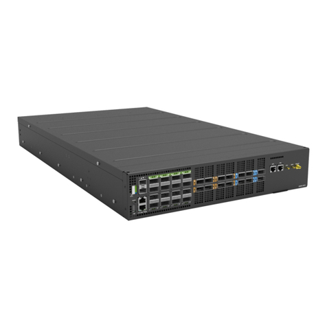
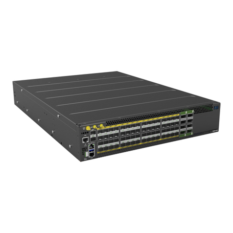
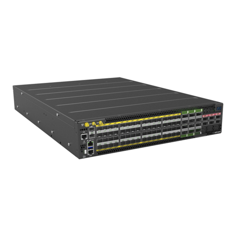
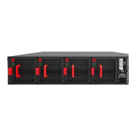
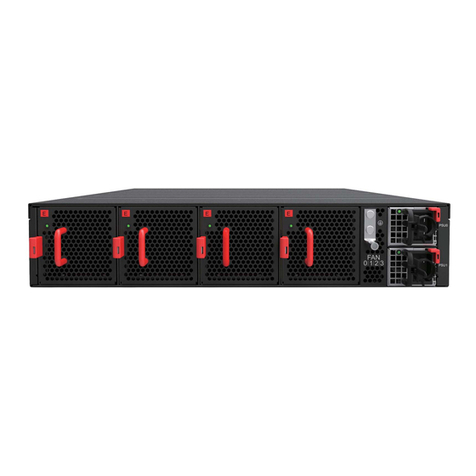
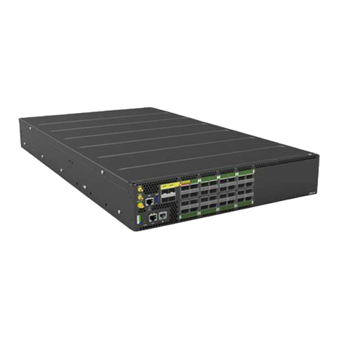
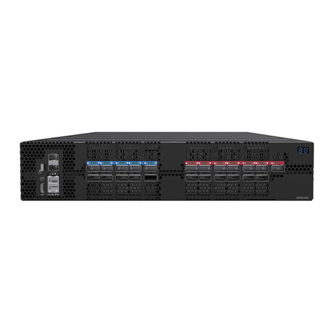
UfiSpace S9705-48D Manual


S9705-48D Hardware Installaon Guide | i
Table of Contents
1 Overview.......................................................................................1
2 Preparaon ...................................................................................2
2.1 Installaon Tools..........................................................................................2
2.2 Installaon Environment Requirements......................................................3
2.2.1 AC Version...........................................................................................3
2.2.2 DC Version...........................................................................................4
2.3 Preparaon Task Checklist...........................................................................5
3 Package Contents ..........................................................................6
4 IdenfyingYourSystem .................................................................7
4.1 S9705-48D Overview ...................................................................................7
4.2 PSU FRU Overview.......................................................................................7
4.2.1 AC Version...........................................................................................7
4.2.2 DC Version...........................................................................................8
4.3 Fan FRU Overview .......................................................................................8
4.4 Port Overview..............................................................................................9
5 MounngtheSwitchinaRack .................................................... 10
6 InstallingtheFanModules........................................................... 11
7 InstallingthePowerSupplyUnits ................................................ 12
8 GroundingtheSwitch .................................................................. 13
9 ConnecngPower ....................................................................... 15
9.1 System Power Consumpon......................................................................15
9.2 Connecng the AC Version PSU.................................................................15
9.2.1 Aaching the AC Power Cord............................................................15
9.2.2 Feeding AC Power .............................................................................15
9.3 Connecng the DC Version PSU.................................................................15
9.3.1 Before Aaching the DC Power Cable...............................................15
9.3.2 Aaching the DC Power Cable ..........................................................17
9.3.3 Tightening the Screws.......................................................................17
9.3.4 Feeding DC Power ............................................................................17
10 VerifyingSwitchOperaon .......................................................... 18
10.1 Front Panel LED .........................................................................................18
10.2 PSU FRU LED ..............................................................................................19
10.3 Fan FRU LED...............................................................................................19
11 InialSystemSetup..................................................................... 20
11.1 Connecng Console Cables .......................................................................20
11.3 Launching a Terminal Emulator ................................................................21
11.4 Accessing CLI .............................................................................................21
S9705-48D Hardware Installaon Guide | ii
12 InstallingtheTransceiver............................................................. 22
13 CauonsandWarnings................................................................ 23
13.1 Cauons and Regulatory Compliance Statements.....................................23
13.2 Installaon Locaon Statement.................................................................24
13.3 Compliance Statements.............................................................................24

S9705-48D Hardware Installaon Guide | 1
1 Overview
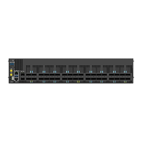
Providing 400GbE fabric ports, the S9705-48D enables the disaggregated architecture required
to fulll the high trac loading in a 5G mobile Ethernet network. As part of USpace’s S9700
Series, the S9705-48D is a robust, exible and carrier-grade router that is coupled with the
S9700-53DX and/or S9700-23D routers for small/medium or large clusters. Suitable for core
networking, the S9705-48D adopts service and fabric routers building blocks to provide carriers
with a beer soluon in place of the tradional chassis
With 1+1 redundancy hot-swappable PSU FRU, 3+1 redundancy hot-swappable Fan FRU,
and a high port density design, the S9705-48D delivers high system reliability, Ethernet
switching performance and intelligence to the network that helps reduce infrastructure and
administrave costs.
This document describes the hardware installaon process for S9705-48D.
S9705-48D PSU, FAN &IO ports conguraons are shown as below:
Managementport IO ports FAN PSU
1 x 10/100/1000BASE-T RJ45 48 x QSFP-DD 3+1 Redundant 1+1 Redundant
2 x 10G SFP+ 8038 FAN Module 2000W PSU
1 x RJ45/Micro USB Serial Console
*Note: Serial Console works either one in the same me and RJ45 has higher priority

S9705-48D Hardware Installaon Guide | 2
2 Preparaon
2.1 InstallaonTools
Screwdriver (Phillips head #2)
Insulaon Wire Lead
Ground Wire
(size #6 AWG)
0.5 +/- 0.02”
(12.7 +/- 0.5 mm)
Philips screwdriver 6-AWG wire for grounding
Crimping Tool
Grounding Lug
Wire Stripping Tool Stripping Tool
• Desktop or laptop with terminal emulaon soware. Refer to secon 11, for details.
• Baud rate: 115200 bps
• Data bits: 8
• Parity: None
• Stop bits: 1
• Flow control: None

S9705-48D Hardware Installaon Guide | 3
2.2 InstallaonEnvironmentRequirements
2.2.1 ACVersion
• Power Reserve: The S9705-48D uses two 1+1 redundant, acve/acve 200 to 240 voltage
AC power supply eld replaceable units. To ensure the acve/acve feed power design
funcons properly, it is recommended that the eld has dual power circuits and has a
reserve of at least 1500 wa on each circuit.
• Space Clearance: The S9705-48D chassis width is 17.16 inches (43.6cm) and shipped with
rail rack kit and adjustable mounng rails suit for 19 inch (48.3cm) wide racks. The depth of
the S9705-48D chassis is 30 inches (76.2cm) without the eld replaceable units (FRUs). The
handle of fan FRU is 1 inch (2.5cm) and the handle of the PSU FRU is 1.5 inches (3.8cm). A
minimum space clearance of 6 inches (15.2cm) is required for the side with the fan FRUs
and PSU FRUs. A total minimum reserve depth for the cabinet is 36 inches (94.4cm).
• Cooling: The S9705-48D airow direcon is front-to-back. Make sure the air ow is in the
same direcon with other equipment in the same rack

S9705-48D Hardware Installaon Guide | 4
2.2.2 DC Version
• Power Reserve: The S9705-48D uses two 1+1 redundant, acve/acve -48 voltage DC power
supply eld replaceable units. To ensure the acve/acve feed power design funcons
properly, it is recommended that the eld has dual power circuits and has a reserve of at
least 1500 wa on each circuit.
• Space Clearance: The S9705-48D chassis width is 17.16 inches (43.6cm) and shipped with
rail rack kit and adjustable mounng rails suit for 19 inch (48.3cm) wide racks. The depth of
the S9705-48D chassis is 30 inches (76.2cm) without the eld replaceable units (FRUs). The
handle of the fan FRU is 1 inch (2.5cm) and the handle of the PSU FRU is 1.5 inches (3.8cm).
A minimum space clearance of 6 inches (15.2cm) is required for the side with the fan FRUs
and PSU FRUs. A total minimum reserve depth for the cabinet is 36 inches (94.4cm).
• Cooling: The S9705-48D airow direcon is front-to-back. Make sure the air ow is in the
same direcon with other equipment in the same rack

S9705-48D Hardware Installaon Guide | 5
2.3 PreparaonTaskChecklist
Task Check Date
Powervoltageandelectriccurrentrequirement:
(AC Version: 200 to 240V AC, 12.5 x 2 ampere maximum
DC Version: -40 to -72V DC, 60 to 33 x 2 ampere maximum)
Installingspaceandweightloadrequirement:
(S9705-48D chassis has a height of 2RU (3.45”/8.8cm), a width of 19”
(48.3cm), and a depth of 30” (76.2cm) without considering cable roung).
Thermalrequirement
(S9705-48D working temperature is 32 to 113°F (0 to 45°C), airow
direcon is front-to-back)
Installingtoolsrequirement
(Screwdriver Philips head #2, Wire-stripping tools for stripping 6-AWG,
crimping tool for ground lug)
Accessoryrequirement
(Desktop or laptop with terminal emulaon soware and USB port)

S9705-48D Hardware Installaon Guide | 6
3 Package Contents
AccessoryList:
Item Descripon Sepc.&Dimensions Q’ty Weight
1
1-1 Grounding Lug
DC Version:
1.54” x 1.47” x 0.49”
(# 6 AWG)
(39 x 37.5 x 12.5mm)
5 pcs 0.14lbs (63.6g)/1 pcs
AC Version:
1.54” x 1.47” x 0.49”
(# 6 AWG)
(39 x 37.5 x 12.5mm)
1 pcs 0.14lbs (63.6g)/1 pcs
1-2 Screw Kit
(for Ground Lug)
2 x Screw M4*L8.0mm
2 x M4 Lock Washers
2 sets 0.01lbs (2.6g)/1 set
1-3 Micro USB Cable 3.28’ (1m) 1 pcs 0.5lbs (24.4g)/1 pcs
1-4 RJ45 to DB9 Female
Cable 8’ (2.4m) 1 pcs 0.27lbs (123.9g)/1 pcs
2
2-1 Adjustable Mounng
Rail (for 4 post)
30.4” x 1.7” x 0.9”
(771 x 44 x 22mm)
(22”~33” rack depth)
2 pcs 7.01lbs (3.2kg)/2 pcs
3.5lbs (1.6kg)/1 pcs
2-2
Screw Kit
(for Rack Mount
Bracket)
2 x Screw M4.0*L5.5mm 2 sets 0.004lbs (1.9g)/1 set
Physicalinformaon:
Componentphysicalinformaon
Weight
Chassis without FRUs 45.2lbs (20.5kg)
S9705-48D full set 54.9lbs (24.9kg)
PSU DC PSU: 2.6lbs (1.2kg)
AC PSU: 2.6lbs (1.2kg)
Fan module 1.1lbs (498g)
Ground lug kit 0.6lbs (66.2g)
Adjustable rail slide 7lbs (3.2kg)
Micro USB cable 0.1lbs (24.4g)
RJ45 to DB9 Female
cable 0.27lbs (123.9g)
AC power cord
(AC version only) 0.7lbs (318g)
Dimension
S9705-48D (W x D x H) 17.16” x 30” x 3.45” (436 x 762 x 87.6mm)
PSU FRU (W x L x H) 1.99” x 14.17” x 1.58” (50.5 x 360 x 40mm)
Fan module (W x H x D 3.15” x 3.15” x 4.8” (80 x 80 x 122mm)

S9705-48D Hardware Installaon Guide | 7
4 IdenfyingYourSystem
4.1 S9705-48D Overview
4.2 PSUFRUOverview
1+1 Redundant, hot swappable power supply eld replaceable unit (PSU FRU).
4.2.1 ACVersion

S9705-48D Hardware Installaon Guide | 8
4.2.2 DC Version
4.3 FanFRUOverview
3+1 Redundant, hot swappable fan eld replaceable unit (FRU).

S9705-48D Hardware Installaon Guide | 9
4.4 Port Overview
Port ID FormFactor MaximumSupportDistance SupportSpeed
0-47 QSFP-DD 328.1 (100m) 400GE

S9705-48D Hardware Installaon Guide | 10
5 MounngtheSwitchinaRack
Caution
It is recommended that switch installaon be done by two individuals. One individual
should hold the switch in posion on the rack, while the other secures it in place using
the rail slide screws.

S9705-48D Hardware Installaon Guide | 11
6 InstallingtheFanModules
The fan module is a hot swappable eld replaceable unit, which can be replaced while the switch is
operang as long as the remaining three modules are installed and in operaon. The fans come pre-
installed and the following steps are instrucons on how to install a new fan module:
1. Press and hold the release tab located on the fan module inward to unlock the old fan
module from the fan bay.
2. While holding down the red tab, grip the handle located on the fan module and gently pull
the old fan module out of the fan bay.
3. Align the new fan module with the fan bay, ensuring that the fan module’s power connector
is in the correct posion.
4. Carefully slide the new fan module into the fan bay and gently push unl it is ush with the
switch case.
5. An audible click will be heard when the fan module is installed correctly. The fan module
will not go in all the way if it is installed in the wrong direcon.
Fan Module:

S9705-48D Hardware Installaon Guide | 12
7 InstallingthePowerSupplyUnits
The power supply unit (PSU) is a hot swappable eld replaceable unit and can be replaced
while the switch is operang as long as the remaining (second) PSU is installed and in operaon
(with 220V power input). The AC and DC PSU follow the same steps for installaon. The PSU
comes pre-installed and the following are instrucons on how to install a new PSU.
Warning
If power input for AC power supply is only 110V, there will only be 1000 was per power
supply and will not be enough power for the power supply to be changed while the
switch is in operaon. In order for AC power supply to be changed while the switch is in
operaon, ensure that 220V power is supplied.
Caution
Shock hazard!
Disconnect all power inputs before servicing.
ACVersion: DCVersion:
1. Press and hold down the release tab located on the PSU inward to unlock the old PSU
from the power bay.
2. While holding down the tab, grip the handle located on the PSU and gently pull the old
PSU out of the power bay.
ACVersion: DCVersion:
3. Align the new PSU with the power bay, ensuring the PSU’s power connector is in the
correct posion.
4. Carefully slide the new PSU into the power bay and gently push unl it is ush with the
switch case.
5. An audible click will be heard when the PSU is installed correctly. The PSU will not go in all
the way if it is in the wrong direcon.

S9705-48D Hardware Installaon Guide | 13
8 GroundingtheSwitch
It is recommended that the switch changes be installed on a ground compliant rack system.
This will reduce or prevent the risk of shock hazards, equipment damage, and potenal of data
corrupon.
The switch can be grounded from the switch chassis and/or the DC power supply units (PSUs).
When grounding the DC PSUs, ensure that both PSUs are grounded at the same me in case
one of them is removed. The grounding wire is not provided with the switch package contents.
M4 screws and washers are provided with the switch package contents
Warning
This equipment must be grounded. Do not defeat the ground conductor or operate
the equipment without a suitably installed ground conductor. Contact the appropriate
electrical inspecon authority or an electrician if you are uncertain about whether your
equipment has been correctly grounded.
The following instrucons are for grounding the switch chassis:
1. Before grounding the switch chassis, ensure that the rack is properly grounded and in
compliance with local regulatory guidelines, ensure that a good electrical connecon to the
grounding point exists, and remove any paint or materials that may prevent good grounding
contact.
2. Strip the insulaon from a size #6 AWG ground wire (not provided), leaving 0.5” +/-0.02”
(12.7mm +/-0.5mm) of exposed grounding wire.
3. Insert the exposed grounding wire all the way into the hole of the ground lug (provided with
switch package contents).
4. Using a crimping tool, rmly secure the grounding wire to the ground lug.

S9705-48D Hardware Installaon Guide | 14
5. Remove yellow tape located on the switch chassis that is covering the holes for securing the
ground lug.
6. Using 2 M4 screws and 4 washers (provided with switch package contents), rmly lock the
ground lug to the switch chassis. ground lug to the switch chassis.

S9705-48D Hardware Installaon Guide | 15
9 ConnecngPower
9.1 SystemPowerConsumpon
The maximum power consumpon of the S9705-48D is 1466 was. It is recommended
that enough power be reserved from the power distribuon system in order to support the
proper funcon of the S9705-48D. Ensure that both PSUs have been properly installed before
powering up the switch, as the S9705-48D is designed to support 1 + 1 power redundancy
9.2 ConnecngtheACVersionPSU
9.2.1 AachingtheACPowerCord
Locate the AC inlet connector on the PSU and plug the AC power cable (250Vac 15A,
IEC60320 C19) into the AC inlet connector.
9.2.2 FeedingACPower
The PSU will immediately output 12V & 5VSB to the system with a 220V, AC power source.
The PSU has a built-in 15 amperes, fast acng fuse based on the PSU maximum capacity,
which will act as a second er system protecon in case the power distribuon unit’s fuse is
not funconing.
Note
If only a 110V AC power source is available, the S9705-48D can sll be powered with
both PSUs providing 1000 was each for a total output of 2000 was. However, in this
case, if one PSU stops funconing, the power output would be inecient to sustain the
switch’s operaon.
9.3 ConnecngtheDCVersionPSU
9.3.1 BeforeAachingtheDCPowerCable
The UL 1015, 6 AWG DC power cable (not provided) must be aached to a two-hole lug
before connecng to the PSU. The following instrucons are for connecng the DC Power
Cable to the lug:
1. Strip the insulaon from a DC Power Cable, leaving 0.5” +/-0.02” (12.7mm +/-0.5mm) of
exposed cable.
2. Insert the exposed DC power cable into the heat shrink tubing, the length of heat shrink
tubing should not less than 38.5mm.
3. Insert the exposed DC power cable all the way into the hollow tube of the lug (provided
with switch package contents).
4. Using a crimping tool, rmly secure the DC power cable to the lug. It is recommended to
not crimp exceeding the lines indicated on the lug, which is also depicted as the cross-
secon area in the picture on the below.

S9705-48D Hardware Installaon Guide | 16
5. Move the heat shrink tubing to cover any exposed metal on the DC power cable and lug.
6. Use a heat source to secure the heat shrink tubing in place. Allow the heat shrink tubing
to cool before aaching the DC power cable. An example of the installed DC version with
insulaon material as below.

S9705-48D Hardware Installaon Guide | 17
9.3.2 AachingtheDCPowerCable
Locate the DC power screw-type terminal block located on the PSU. Remove the plasc cover
that is protecng the terminal block by pushing from the top or boom of the cover and
ipping open the cover outwards (Top picture). Secure the two-hole lug (with the DC power
cable aached) to the terminal block (Middle picture). Put plasc cover back on terminal
block to guard against contact with terminals (Boom picture).
9.3.3 TighteningtheScrews
Tighten the screws to a torque value of 14.0+/-0.5kgf.cm. If the torque is not enough, the
lug will not be secure and may cause malfuncons. If the torque is too much, the terminal
block or lug may be damaged. The previous picture depicts how it should look once the lug is
aached and the protecve plasc cover reinstalled.
9.3.4 8.3.4.FeedingDCPower
The PSU will immediately output 12V and 5VSB to the system with a -48V DC power source.
The PSU has a built in 80 amperes, fast acng fuse based on the PSU maximum capacity,
which will act as a second er system protecon in case the power distribuon unit’s fuse is
not funconing.
Other manuals for S9705-48D
1
Table of contents
Other UfiSpace Network Router manuals

UfiSpace
UfiSpace S9700-23D Manual

UfiSpace
UfiSpace S9600-30DX Manual

UfiSpace
UfiSpace S9701-82DC Manual

UfiSpace
UfiSpace S9705-48D Manual

UfiSpace
UfiSpace S9600-72XC Manual

UfiSpace
UfiSpace S9601-104BC Manual

UfiSpace
UfiSpace S9600-32X Manual

UfiSpace
UfiSpace S9610-36D Manual

UfiSpace
UfiSpace S9600-56DX Manual

UfiSpace
UfiSpace S9600-28DX Manual