Uflex PADDLE TRIM User manual

Installation Manual
PADDLE TRIM
PARTNER
(drw. n°31733 30/10/2015)

“Established in 1989 USA is a leader in steering and control systems for the marine industry.
With full manufacturing capabilities in Sarasota, Florida, USA can support all sectors of
the marine industry regardless of volume and/or product requirements. And, as an affliate of the
Group. USA has tremendous resources to draw upon for new product development
in hydraulics, electronics and many other technologies.
Innovative product design and unparalleled dedication to quality customer service and products
continue to be cornerstone of USA’s growth. Today our products can be found as originally
installed equipment on many of the most widely known and respected boat brands in the world.
Aftermarket parts can be sourced from trained and experienced distributor network troughout North
and South America.
Our dedication to providing the highest quality products and service is only matched by our
commitment to developing new products employing the lastest materials and technology to enhance
our customer’s boating experience. From steering wheels to sophisticated electronic controls,
USA has everything you need to make sure that your boat looks and perform it’s best for many, many
years.”
Sarasota, FL 34243 - 6442 Parkland Drive
USA
Dear Customer,
Thank you for choosing an product.
has been a reference in steering systems in the field of recreational and professional
boating for years.
production has always been synonymous with great reliability and safety.
All the products are designed to guarantee the best performance in relation to the
purpose for which they were designed.
To protect your safety and to maintain high quality standards guarantees its products
only when used with original parts.
The Quality Management Systems and are certified CISQ-IQNet by RINA Italian
Naval Register, in accordance with the UNI EN ISO 9001:2000 standard. Certificate no.
6669/02/S (formerly 420/96). Certificate no. 8875/03/S.
The Quality system involves all the company resources and processes starting from the design to:
• guarantee product quality to the Customer;
• implement the actions necessary to maintain and improve the quality standards over time;
• pursue continuous improvement of process effectiveness and efficiency in order to always be in
tune with the needs of the market and to increase Customer satisfaction.

Installation Manual
PADDLE TRIM - page 3
CONTENTS
DOCUMENT REVISIONS............................................................................................................................4
USING THE MANUAL AND THE SYMBOLS USED........................................................................................4
GENERAL INFORMATION..........................................................................................................................5
WARRENTY...............................................................................................................................................6
RETURNPOLICY.........................................................................................................................................7
SECTION 1 - PRODUCT DESCRIPTION
1.1 PADDLE TRIM DESCRIPTION....................................................................................................8
1.2 CONFIGURATIONS....................................................................................................................9
1.3 PACKAGECONTENTS...............................................................................................................10
SECTION 2 - INSTALLATION
2.1 TOOLS REQUIRED FOR THE INSTALLATION.............................................................................12
2.2 INSTALLING THE PADDLE TRIM..............................................................................................12
INSTALLATION ON TILT...........................................................................................................13
INSTALLATIONS ON HYDRAULIC FRONT MOUNTING PUMPS..................................................16
2.3 ELECTRICAL CONNECTION.....................................................................................................18
SECTION 3 - SAFETY WARNINGS
3.1 SAFETY RULES DURING INSTALLATION AND USE................... ...............................................19
SECTION 4 - MAINTENANCE
4.1 MAINTENANCE.......................................................................................................................20
SECTION 5 - DISPOSAL
5.1 DISPOSAL..............................................................................................................................20

Installation Manual
page 4 - PADDLE TRIM
USING THE MANUAL AND THE SYMBOLS USED
The INSTALLATION MANUAL is the document that accompanies the product from the time of its sale
until its replacement and disposal. It is therefore to be considered an integral part of the product.
It is a requirement to read the manual before undertaking ANY ACTIVITIES that involve the product.
In order to protect the safety of the user and to ensure the proper functioning of the product, the
symbols described below have been adopted in this manual.
DOCUMENT REVISIONS
REV. DATE REVISION DESCRIPTION
008/06/2015 First release
Indicates a reminder of safety practices or unsafe practices that could
cause injury or damage to the product or environment.
CAUTION
DANGER
Indicates that there is a serious inherent danger that could lead to a high
probability of death or serious injury if the appropriate precautions are not
taken.
NOTE
Important Information to highlight for a proper installation and maintenance,
but that will not cause damage.
It indicates that there is a hazard that can cause injury or death if appropriate
precautions are not taken.
WARNING
The operations for the execution of which qualified or specialised personnel
are required in order to avoid possible risks, are highlighted with the symbol
shown to the side.
It is recommended to train personnel for the installation of the product and
ensure that the provisions are both understood and implemented.

Installation Manual
PADDLE TRIM - page 5
GENERAL INFORMATION
This installation manual is an integral part of the product and must be readily available to its users
and maintenance personnel.
The user is required to know the contents of this manual.
assumes no responsibility for any inaccuracies due to printing errors, contained in the
manual.
Without prejudice to the essential characteristics of the product described, reserves the right
to make any changes, as thought fit, to descriptions, details and illustrations for the improvement
of the product, or for manufacturing or commercial reasons, at any time and without undertaking to
update this publication.
ALL RIGHTS RESERVED. The publishing rights, trademarks, initials and the product photographs
shown in this manual are the property of and any reproduction, even partial, is prohibited.
Every care has been taken in collecting and checking the documentation to make this manual as
complete and comprehensible as possible. Nothing contained in this publication may be construed
as a guarantee or condition, express or implied, including, but not limited to, the guarantee of fitness
for a particular purpose.
Furthermore, nothing contained in this publication can be interpreted as modifying or asserting the
terms of any purchase contract.
WARNING
In order to ensure the proper functioning of the product and its components, it must be installed
by expert personnel. In the event of component parts failure or malfunctions, please contact the
specialised personnel or our Technical Service Department.
TECHNICAL ASSISTANCE SERVICE
North - South - Central America:
UFLEX USA
6442 Parkland Drive
Sarasota, FL 34243
Tel: +1.941.351.2628
Fax: +1.941.360.9171
Email: [email protected]
www.uflexusa.com
UFLEX S.r.l.
Via Milite Ignoto,8A
16012 Busalla (GE)-Italy
Tel: +39.010.962.0239 (Italy)
Tel: +39.010.962.0244 (abroad)
Fax: +39.010.962.0333
Email: [email protected]
www.uflexgroup.it

Installation Manual
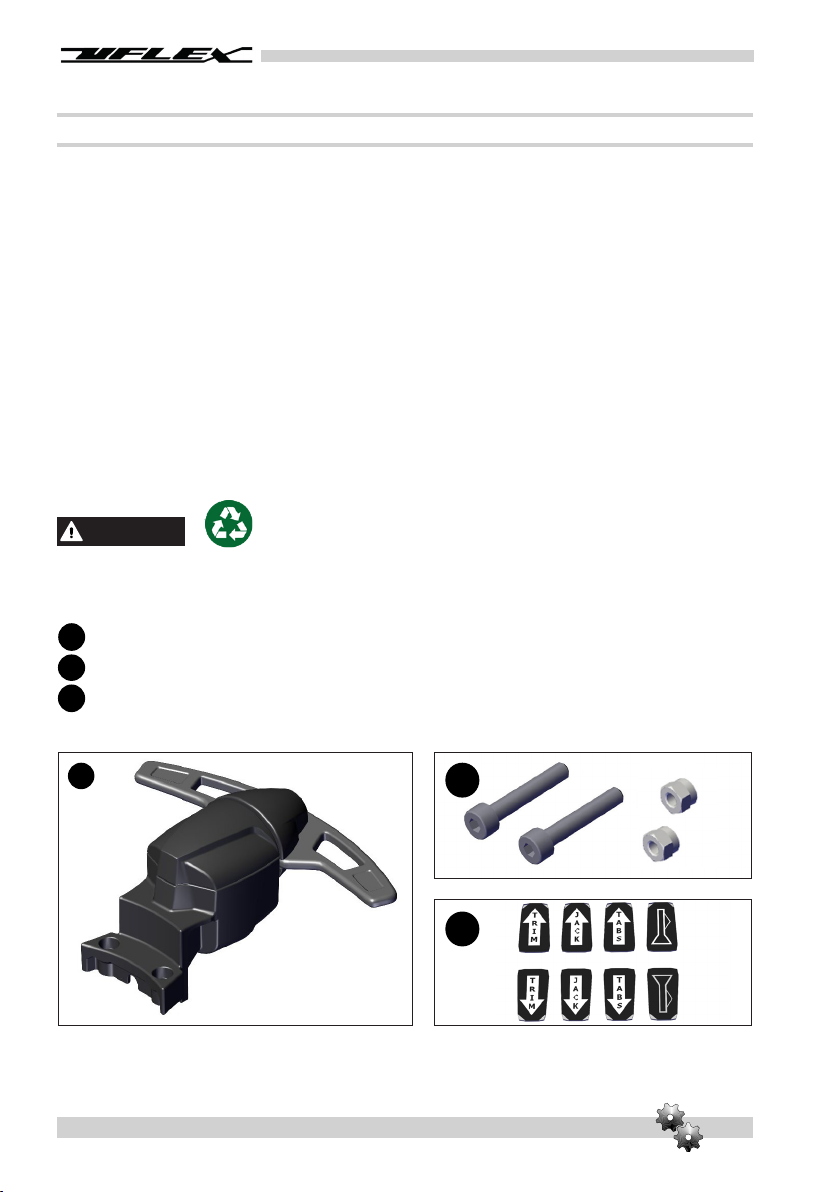
page 6 - PADDLE TRIM
WARRANTY
1. Two Year Limited Warranty. USA, Inc. warrants that all products manufactured by USA,
Inc. or S.p.A. and sold by USA to the retail purchaser (“Purchaser”) that for two
(2) years after the date of manufacture to be free from defects due to material or workmanship,
subject to the exclusions below. Improper installation AVOIDS this warranty. Installation should
only be attempeted by a trained and qualified technician.
2. Exclusions.This limited warranty does not cover and does not extend to any of the following:
(a) Failure caused by normal wear and tear, climatic conditions, misure, neglect, lack of
proper maintenance, accident, fire or other casualty damage, racing, overloading, negligence,
modification,beaching or grounding of vessel, collision, impact, towing, acts of war or hostilities;
(b) components not manufactured by USA, Inc., or its affiliates; (c) cost of removal or
reinstallation of any component (including components manufactured by USA, Inc.)
or disassembly or reassembly of the unit containing the component; (d) components not
manufactured by USA, Inc. or S.p.A., whether or not warranted by the other
manufacturer; (e) any product which has not been properly installed.
3. Limitations. THE REPAIR OR REPLACEMENT OF DEFECTIVE PARTS SHALL BE PURCHASER’S SOLE
AND EXCLUSIVE REMEDY AND USA, INC,’S SOLE AND EXCLUSIVE LIABILITY UNDER THIS
WARRANTY. LABOR FOR REPLACEMENT IS NOT INCLUDED. USA, Inc.’s obligation under this
warranty is limited to the repair or replacement (at USA, Inc.’s sole election) of any covered
item found to be defective, when delivered by Purchaser pursuant to written authorization and
instructions from USA, Inc., shipping prepaid to USA, Inc.’s plant or other designated
repair facility. Repaired or replaced items are warranted as provided herein for the unexpired
portion of the applicable warranty period. THIS WARRANTY, AND THE RIGHTS AND REMEDIES UNDER
IT, IS EXCLUSIVE AND IS GIVEN IN PLACE OF ALL OTHER WARRANTIES, WHETHER EXPRESS OR
IMPLIED, INCLUDING ANY IMPLIED WARRANTY OF MERCHANTABILITY OR FITNESS FOR PARTICULAR
PURPOSE, WHETHER ARISING BY LAW, CUSTOM, CONDUCT OR USAGE OF TRADE, PURCHASER’S
REMEDIES SHALL BE LIMITED AS STATED HEREIN AND USA, INC. SHALL NOT BE LIABLE FOR
ANY INCIDENTAL, CONSEQUENTIAL OR INDIRECT DAMAGES OR LOSSES RESULTING FROM DEFECTS.
THE RETAIL SELLER IS NOT A CO-WARRANTOR AND IS NOT AUTHORIZED BY USA, INC. TO
AMEND OR MODIFY THIS LIMITED WARRANTY IN ANY MANNER.
4. Transferability of Warranty. This limited warranty may not be transferred to subsequent
purchasers.
5. Miscellaneous. USA, Inc. is an affiliate of S.p.A. , USA, Inc., reserves the
right to make changes in the design and construction of its products at any time, without notice
and without any obligation to incorporate such changes into products of prior manufacture.
This limited warranty applies to new components sold by USA, Inc.. This limited warranty
contains the entire agreements between USA, Inc. and Purchaser and suspersedes all
prior agreements, discussions, negotiations, commitments and representations, whether oral
or written, between them regarding USA, Inc’s warranty. If any provision of this limited
warranty, or the application of it, is determined to be invalid of unenforceable for any reason, the
remainder of this limited warranty and the application of it shall not be affected.

Installation Manual
PADDLE TRIM - page 7
Return policy
Any product that is presumed defective should be reported to USA within 48 hours of receipt or
discovery in the field. Upon notification USA will attempt to troubleshoot the problem with our
customer over the phone. If we are unable to resolve the problem will issue a Return Goods
Authorization number and we require that the product in question be returned to with all its
parts in its original packaging. The product should be returned freight prepaid to:
Upon receipt will examine the product to determine the cause of the defect. If the product is
determined to have a defect in workmanship or material, it will be repaired at our discretion.
Our warranty does not cover labor, towing or other expenses. Further, it does not cover products that
have been improperly installed, damaged in installation, misapplied, or misused.
Our products are not intended for use in racing applications.
UFLEX USA
RGA Department - RGA #
6442 Parkland Drive
Sarasota, Florida 34243
6. Ultron 3000 and PowerC. The Ultron 3000 and “PowerC - User and Installation Manual” describes
activities, operations, technical specifications which must be followed during the installation
and/or usage of the product, in order to keep a valid warranty. Descriptions and drawings in that
manual are suitable to allow installation and use of the product to skilled persons. In case of
doubt and/or for any information, please contact our Technical Service.
All communications and notices from Purchaser regarding this limited warranty should be sent to:
USA, INC., 6442 Parkland Drive, Sarasota, FL 34243; (941) 351-2628.

page 8 - PADDLE TRIM
Installation Manual
1 - PRODUCT DESCRIPTION
1.1 Paddle Trim Description
The Paddle Trim is a control system operating at 12VDC/24VDC, inserted between the wheel and
steering system.
The system can be adapted to front mount hydraulic steering and to hydraulic and
mechanical steering systems for mounting with tilt.
The Paddle Trim has been ergonomically designed to allow the driver to adjust the following functions,
without taking his hands off the steering wheel:
• engine trim
• jack plate
• trim tabs
• horn.
CAUTION
Any other application apart from those shown in this manual ARE NOT ALLOWED.

PADDLE TRIM - page 9
Installation Manual
1.2 Congurations
The Paddle Trim can be adapted to FRONT MOUNTING hydraulic steering systems (UP20F,
UP25F, UP28F, UP33F, UP39F, UP45F) or steering systems with TILT (mechanical or hydraulic). Both
versions can be configured with single or dual control.
SINGLE CONTROL DEVICE WITH TILT
CONFIGURATION
SINGLE CONTROL DEVICE WITH FRONT
MOUNTING HYDRAULIC PUMP CONFIGURATION
DUAL CONTROL DEVICE WITH TILT
CONFIGURATION
DUAL CONTROL DEVICE WITH FRONT MOUNTING
HYDRAULIC PUMP CONFIGURATION

page 10 - PADDLE TRIM
Installation Manual
1.3 Package contents
Before installation of the equipment check that it has not suffered any damage due to transport or
storage conditions.
Verify also that all the supplied components are effectively contained in the package (see list).
In case of damage or an incomplete delivery, notify the complaint to the courier and advise your
supplier.
For a complete installation of the SINGLE control device, the user should have 2 packages:
• SINGLE CONTROL DEVICE
• MOUNTING BRACKET FOR HYDRAULIC FRONT MOUNTING STEERING SYSTEM OR STEERING SYSTEM
WITH TILT
For a complete installation of the DUAL control device, the user should have 3 packages:
• SINGLE CONTROL DEVICE (x2)
• MOUNTING BRACKET FOR HYDRAULIC FRONT MOUNTING STEERING SYSTEM OR STEERING SYSTEM
WITH TILT
CAUTION
The packing must be disposed of according to applicable directives.
CONTENTS OF THE SINGLE CONTROL DEVICE PACKAGE
qty.1 control device
qty.2 M4 screws + qty.2 nuts
labels
A
B
C
AB
C

PADDLE TRIM - page 11
Installation Manual
CONTENTS OF THE MOUNTING BRACKET FOR STEERING SYSTEMS WITH TILT PACKAGE
(mechanical or hydraulic)
qty.2 mounting half-brackets for steering system with tilt
qty.2 M4 screws
qty.2 half-covers
CONTENTS OF THE MOUNTING BRACKET FOR HYDRAULIC FRONT MOUNTING STEERING
SYSTEMS
(compatible with hydraulic front mounting steering systems UP20F, UP25F, UP28F, UP33F,
UP39F, UP45F)
qty.2 mounting half-brackets for hydraulic front mounting steering systems
qty.2 M4 screws
D
E
F
D E
F
G
H
GH

Installation Manual
page 12 - PADDLE TRIM
2 - INSTALLATION
2.1 Tools required for the installation
3 mm male
hexagonal key
2.2 Installing the Paddle Trim
The control device can be attached on both types of half-bracket in three different positions, at
the most comfortable angle according to taste.
7 mm
spanner
1 2 3

Installation Manual
PADDLE TRIM - page 13
Installation on tilt
2Before attaching the bracket to the tilt the surface that will be in contact with the bracket
should be thoroughly degreased. The half-brackets must be positioned so that they rest on the
tilt (5).
1Attach the control device (1) under the mounting half-bracket (2) with the M4 screws (3)
and nuts (4) using a torque of 3 Nm (2.21 lbft).
For applications with dual command, repeat the procedure on the second device.
1
4
3
2
5

Installation Manual
page 14 - PADDLE TRIM
Attach the bracket to the steering system by means of the M4 screws (6) with a torque of 3 Nm
(2.21 lbft).
Once the bracket has been attached, position the half-covers (7) on their respective half-brackets
(8).
8
7
6

Installation Manual
PADDLE TRIM - page 15
3Once the bracket has been attached to the tilt, block the electrical cable in the cable clips
(9) on the lower part of the bracket.
CAUTION
The installer must consider sufficient cable length to allow tilting of the mechanism avoiding that
this movement can compromise the electrical connection to the device.
9

Installation Manual
page 16 - PADDLE TRIM
2Before attaching the bracket to the steering system the surface that will be in contact
with the bracket should be thoroughly degreased. The mounting bracket can be installed in any
position as long as it is on the cylindrical surface of the steering system (14).
1Pass the control device electrical cable through the hole provided in the half-bracket (10)
beforehand. Attach the control device (11) on top of the mounting half-bracket with the M4 screws
(12) and nuts (13) with a torque of 3 Nm (2.21 lbft).
For applications with dual command, repeat the procedure on the second device.
Installation on hydraulic front mounting pumps
11
10
12
13
14

Installation Manual
PADDLE TRIM - page 17
Attach the bracket to the steering system by means of the M4 screws (15) with a torque of 3 Nm
(2.21 lbft).
3Once the bracket has been attached to the steering system, block the electrical cable in
the cable clips (16) on the lower part of the bracket.
15
16

Installation Manual
page 18 - PADDLE TRIM
2.3 Electrical connection
Connect the electrical conductors of the Paddle Trim as follows:
DANGER
The system will work only with 12VDC/24VDC power. DO NOT INSTALL ON SYSTEMS WITH DIFFERENT
VOLTAGES FROM THESE!
CAUTION
Power limits: the device can be used with a resistive load of up to 5A and/or a maximum inductive
load of 2A.
CAUTION
Once the electrical connections to the control device have been made, before attempting to drive
the boat, perform a verification test to ensure that the system responds correctly to the commands
given through the device.
White: normally open
Red: normally open
Black: common

PADDLE TRIM - page 19
Installation Manual
3 - SAFETY WARNINGS
3.1 Safety rules during installation and use
The precautions and safety criteria given in this manual MUST BE STRICTLY OBSERVED.
declines any responsibility in the event that the user does not observe them, and is not responsible
for any type of negligence that may be committed during the use of the system.
CAUTION
• Putting hands on the inside of the steering wheel during navigation can be dangerous. Only
give commands to the device keeping the hands on the outside of the steering wheel.
• Do not modify or add devices to the system, without written authorisation or prior technical
intervention by showing the modification in the description of the intervention.
• Do not use the equipment for a purpose different from that for which it was intended, as
specified in the installation manual.
• Do not allow non-specialised personnel to perform the installation.
DANGER
The system will work only with 12VDC/24VDC power. DO NOT INSTALL ON SYSTEMS WITH
DIFFERENT VOLTAGES FROM THESE!
CAUTION
Any other applications apart from those shown in this manual ARE NOT ALLOWED.

page 20 - PADDLE TRIM
Installation Manual
4 - MAINTENANCE
4.1 Maintenance
Wipe the system using non-aggressive and non-abrasive soap and water.
5 - DISPOSAL
5.1 Disposal
If, for any reason, you intend to put the control device out of service dispose of the components in
accordance with the regulations in force.
Table of contents
Other Uflex Boating Equipment manuals
Popular Boating Equipment manuals by other brands

SOMAG
SOMAG NSM 400 user manual

Sleipner
Sleipner MIDI 202 installation guide

Skipper
Skipper DL850 Operation and installation manual

Classic Accessories
Classic Accessories Orion Instructions & Care

Hunter
Hunter 27 BIMINI installation instructions

Seastar Solutions
Seastar Solutions i7700 Operation instructions