Ugin PROGRAMIX 50 User manual

INSTRUCTIONS FOR USE
Burnout furnace
PROGRAMIX 50 & PROGRAMIX 100
Rév. 031121

Instructions for use (rev 031121) - En
PROGRAMIX 50 - 100
UGIN DENTAIRE
2
PROGRAMIX 50 & PROGRAMIX 100
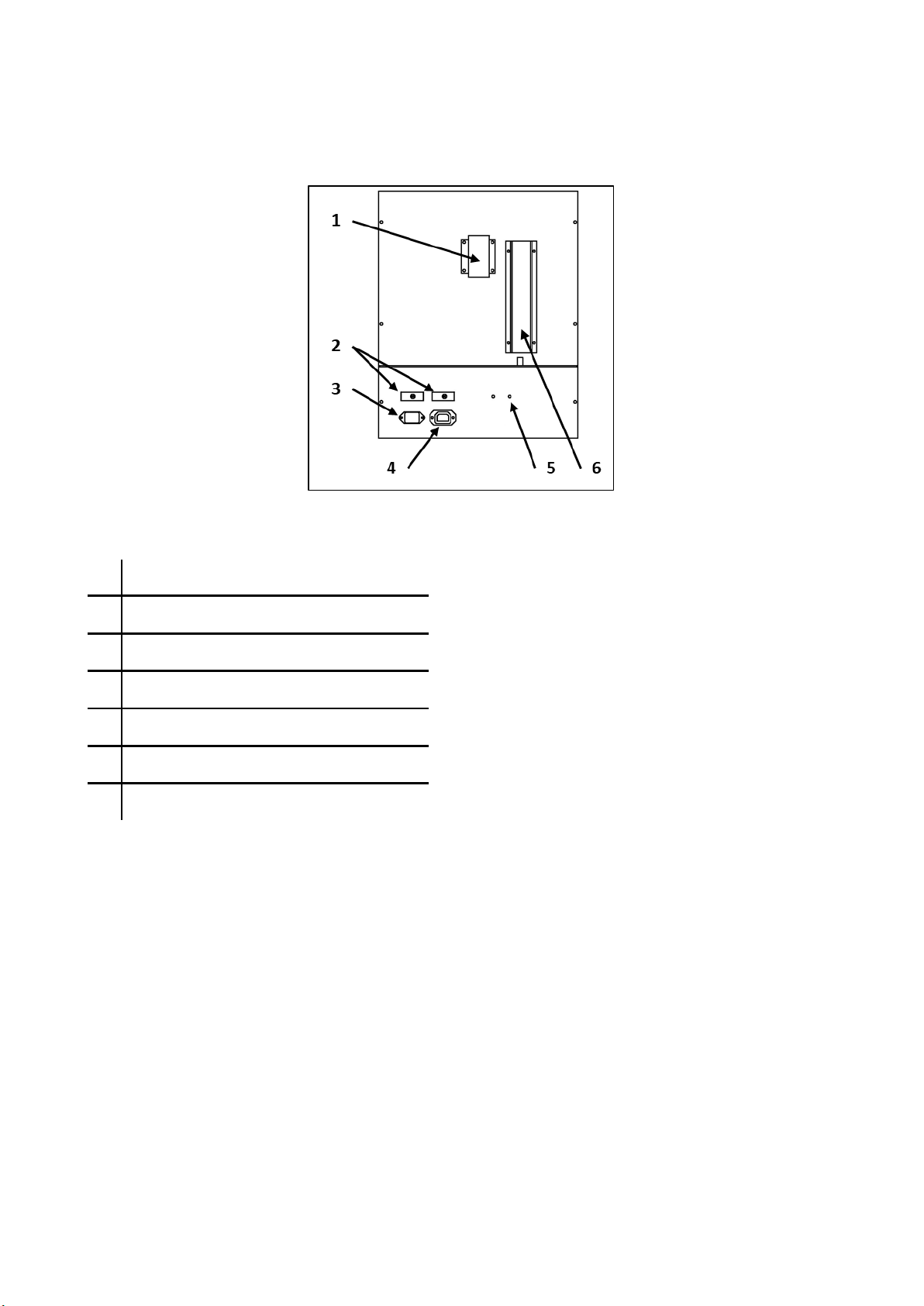
A. EQUIPMENT DESCRIPTION.......................................................................................................................3
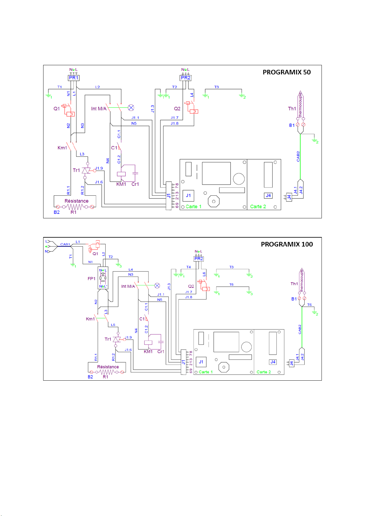
B. ELECTRICAL DIAGRAM .............................................................................................................................4
C. INSTRUCTIONS FOR USE ..........................................................................................................................5
1. SAFETY INSTRUCTIONS .....................................................................................................................5
1.1. USE ............................................................................................................................................5
1.2. SAFETY INSTRUCTIONS ..............................................................................................................5
1.3. WASTE DISPOSAL.......................................................................................................................6
2. EC DECLARATION OF CONFORMITY..................................................................................................6
3. TECHNICAL INFORMATION...............................................................................................................7
3.1. TECHNICAL DATA.......................................................................................................................7
3.2. CONDITIONS OF USE, TRANSPORT AND STORAGE ....................................................................8
3.3. ACCESSORIES .............................................................................................................................8
4. INSTALLATION AND START-UP..........................................................................................................8
4.1. UNPACK.....................................................................................................................................8
4.2. INSTALLATION ...........................................................................................................................9
4.3. START-UP...................................................................................................................................9
5. PROGRAMMING .............................................................................................................................10
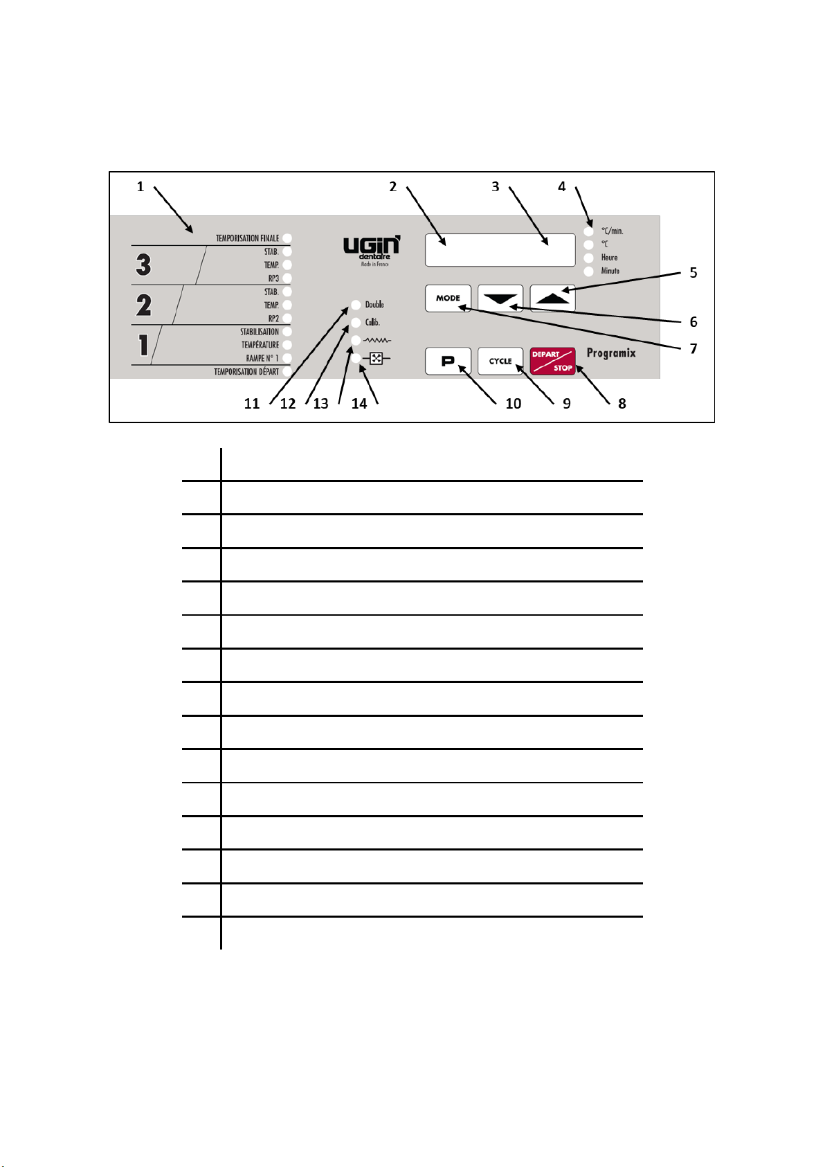
5.1. Description of the control panel..............................................................................................10
5.2. OPERATING PARAMETERS.......................................................................................................11
5.3. DEPARTURE DELAY ..................................................................................................................11
5.4. 1st, 2nd AND 3rd STAGE AND DELAY FINAL.................................................................................11
5.5. PROGRAM NUMBER DISPLAY ..................................................................................................12
5.6. TEMPERATURE/TIME DISPLAY.................................................................................................12
5.7. INDICATOR OF THE UNIT DISPLAYED ON THE PANEL (No. 3)...................................................12
5.8. MODE KEY ...............................................................................................................................12
5.9. FORWARD AND REVERSE KEY..................................................................................................12
5.10. START/STOP TOUCH CONTROL................................................................................................13
5.11. CYCLE ADVANCE KEY ...............................................................................................................13
5.12. PROGRAM SELECTION KEY ......................................................................................................13
5.13. INDICATORS.............................................................................................................................13
6. USE .................................................................................................................................................14
7. CALIBRATION..................................................................................................................................15
8. PROTECTION...................................................................................................................................16
9. MAINTENANCE AND TROUBLE-SHOOTING.....................................................................................17
9.1. MAINTENANCE ........................................................................................................................17
9.2. TROUBLE-SHOOTING..................................................................................................................18
9.3. THERMOCOUPLE REPLACEMENT.............................................................................................19
9.4. MUFFLE REPLACEMENT...........................................................................................................19
10. TABLE OF PROGRAMS.....................................................................................................................20
10.1. TABLE OF SINGLE PROGRAMS (No. 0 to No.19) ......................................................................20
10.2. TABLE OF DOUBLE PROGRAMS (No. 20 to No. 29) .................................................................21
Non-contractual images
Translation into English from original in French

Instructions for use (rev 031121) - En
PROGRAMIX 50 - 100
UGIN DENTAIRE
3
A. EQUIPMENT DESCRIPTION
Rear panel
N°
DESCRIPTION
1
Chimney outlet
2
Thermal fuse
3
Power socket
4
Fumes extractor connection socket
5
Location of triac
6
Thermocouple cover

Instructions for use (rev 031121) - En
PROGRAMIX 50 - 100
UGIN DENTAIRE
4
B. ELECTRICAL DIAGRAM

Instructions for use (rev 031121) - En
PROGRAMIX 50 - 100
UGIN DENTAIRE
5
C. INSTRUCTIONS FOR USE
1. SAFETY INSTRUCTIONS
1.1. USE
Programix 50 and Programix 100 burnout furnaces are intended use to heating the coated cylinders. These
furnaces have to be operated only by dental professionals.
Programix 50 and Programix 100 have to use in the conditions and for the uses described in this manual.
Any other use that will be made of it (such as firing other materials, heating food products, etc.) is considered
inappropriate. In this case, the manufacturer declines all liability and immediately cancels the equipment
warranty.
According to the product’s instructions and functionalities, it is imperative to read carefully the manual
before furnace installation and operations. Retain the manual for future reference.
1.2. SAFETY INSTRUCTIONS
Pictograms’ meaning used in these instructions for use:
General warning
Electrical hazard
Burn hazard - Hot surface
Observe following safety instructions:
-During operation and after use, the furnace surfaces and door may reach high temperatures:
do not touch.
-Wear suitable gloves for handling cylinders after heating.
-The unit has to be connected to an electrical installation in accordance with the applicable
standard in the country in which it is being used. This installation has to provide protection
against overcurrent, overload and ground faults.
-This furnace requires its own power line and has to be connected to a circuit breaker.
-Connect it directly to the mains socket. Do not use multiple sockets.
-Ensure that the connection cables are in perfect condition to prevent short circuits.
-Before any technical intervention, the unit has to be switched off (with the breaker) and
disconnected from the mains power supply.
-Do not spill liquid on the ventilation openings or inside the furnace.
-The furnace must be placed on a flat surface, keeping sufficient clearance around the unit to
ensure proper ventilation.
-Do not block the ventilation openings to avoid overheating.
-The heating chamber contains insulating material composed of high temperature insulation
wool (alkaline earth silicate), a substance not classified as dangerous according to Regulation
1272/2008/EC (CLP). Handle carefully.
-Dust can be released: remove with a vacuum cleaner - do not blow or use compressed air.

Instructions for use (rev 031121) - En
PROGRAMIX 50 - 100
UGIN DENTAIRE
6
-Use only genuine spare parts. The use of non-original spare parts voids any warranty for your
device.
-Do not introduce stranger objects inside the unit during the maintenance operations. It is
forbidden to modify the material without authorization.
-Do not execute different operations of maintenance from those brought back in the manual.
Any operation not included in this manual can involve risks.
-For any further information concerning installation, maintenance and use, contact the
customer’s service UGIN DENTAIRE.
1.3. WASTE DISPOSAL
Observe the waste disposal regulations for electrical and electronic equipment: do not dispose of with
household waste.
The unit is subject to Directive 2012/19/EU on waste electrical and electronic equipment and to the laws of
the country in which it is being used and must be disposed of in accordance with applicable regulations.
The insulating material are composed of high temperature insulation wool (alkaline earth silicate), a
substance not classified as dangerous according to Regulation 1272/2008/EC (CLP), and classified as non-
hazardous waste for disposal. However, such a waste is normally dusty and so must be properly packaged
before for disposal. Check any national or regional applicable regulations.
2. EC DECLARATION OF CONFORMITY
The equipment’s EC declaration of conformity is provided as appendix of instructions for use.
Content of the declaration EC:
▪Name and address of the manufacturer:
UGIN DENTAIRE. 25 rue de la Tuilerie. 38170 SEYSSINET-PARISET –FRANCE
▪UGIN DENTAIRE declares, on its own exclusive responsibility, that the product:
- Burnout furnace PROGRAMIX 50 or PROGRAMIX 100
- Serial number: see the equipment’s EC declaration of conformity
▪Fulfills the essential requirements of health and safety of the following directives:
- Machinery directive 2006/42/EC
- Electromagnetic compatibility directive 2014/30/EU

Instructions for use (rev 031121) - En
PROGRAMIX 50 - 100
UGIN DENTAIRE
7
3. TECHNICAL INFORMATION
3.1. TECHNICAL DATA
Programix 50 and Programix 100 burnout furnaces are intended use to heating the coated cylinders. These
furnaces have to be operated only by dental professionals and in the conditions described in this manual (see
chapter 1.1 and 3.2).
TECHNICAL DATA
PROGRAMIX 50
PROGRAMIX 100
Maximum temperature
-in constant use
1050°C / 1922°F
-temporary peak
1150°C / 2102°F
Time programming
0 to 100 hours
Heat rise rate:
-regulated position
1 to 15°C/min
-full position
16°C/min and more
Numbers of programs
30 programs
Regulation
program No. 0 to 19: 3 stages
program No. 20 to 29: 6 stages
Thermocouple
type K
Numbers of cylinders
(diameter 80 mm, length 55 mm)
4 to 6 cylinders
8 to 12 cylinders
Supply voltage
230 V –50/60 Hz
Maximum power consumption
2 000 W
3 000 W
Dimensions (furnace) (mm)
(height, width, depth)
500 x 390 x 440
590 x 465 x 555
Chamber size (mm)
(height, width, depth)
120 x 170 x 210
150 x 220 x 300
Weight
34 kg
56 kg

Instructions for use (rev 031121) - En
PROGRAMIX 50 - 100
UGIN DENTAIRE
8
3.2. CONDITIONS OF USE, TRANSPORT AND STORAGE
▪Authorised conditions of use
-Ambient temperature: +5°C to +40°C
-Humidity range: maximum relative humidity 80% for temperatures until 31°C, without condensation and
decrease linear until 50% to 40°C, without condensation.
-Ambient pressure: up to an altitude of 2000 m above sea level.
▪Authorised conditions of storage
-Ambient temperature: -20°C to +65°C
-Humidity range: maximum relative humidity 80%
-Ambient pressure: up to an altitude of 2000 m above sea level.
▪Conditions to transport
-Wait the complete cooling before packing/transporting.
-Use the original packaging only, with the protective elements.
-Take hold the furnace by its base.
-Install the furnace in the packaging with the protective elements. Also protect the accessories for
transportation.
3.3. ACCESSORIES
▪Accessories delivered with the furnace (included in the packaging)
DESCRIPTION
CODE UGIN
Refractory plate to Programix 50 (160x210)
FCH05THE0044
Refractory plate to Programix 100 (210x280)
FCH05THE0037
▪Accessory recommended (not delivered with the furnace –to order separately)
DESCRIPTION
CODE UGIN
Fumes extractor
FCH01EXT0001
4. INSTALLATION AND START-UP
4.1.UNPACK
- Unpack PROGRAMIX 50 / 100 and check that it is in perfect order (furnace and accessories).
- Any defects can be reported to the carrier.
- Remember to get the carrier to sign the delivery note.
NOTE: keep the original packaging to transport the furnace (see chapter 3.2).

Instructions for use (rev 031121) - En
PROGRAMIX 50 - 100
UGIN DENTAIRE
9
4.2. INSTALLATION
NOTE: for marks, see chapter A –equipment description.
-Install in a ventilated room. Observe the conditions indicated in chapter 3.2.
-Place the furnace on a flat, level and clear surface. Keep a distance from other objects around not less
than 10 cm. Keep it away from heat sources (radiators and/or other equipment that release heat). Avoid
vibrations and shocks
-Dust, corrosive or explosive gases can damage the body and the insulation.
-The furnace must not be used or placed in a place where there is a risk of explosion.
-Its forbidden placing inflammables, toxic, volatile or explosives around the furnace.
This unit requires its own power line and has to be connected to a circuit breaker. Grounding
is mandatory to avoid accidents and the dangers of overheating the power line. Connect it
directly to the primary socket, do not use multiple sockets (risk of electrical interference).
▪Fumes extractor installation
UGIN DENTAIRE recommends installing a fumes extractor on the PROGRAMIX 50 / 100 in order to achieve
optimal gas evacuation. It will be installed in place of the chimney outlet. It is recommended to use the UGIN
DENTAIRE fumes extractor.
Installation procedure to UGIN DENTAIRE fumes extractor:
- Remove the chimney outlet (No. 1): unscrew.
- Instead install the fumes extractor: screw.
- Connect it to the fumes extractor connection socket (n ° 4).
- Through this connection, the fumes extractor is connected with the furnace programmer which will start
and stop it as needed.
IMPORTANT: PROGRAMIX 50/100 can be connected a fumes extractor or extractor hood within or
without external control independent of the furnace and a maximum power of 20W.
If non-observance of these instructions: risk of material damage (overintensity) and may voids any
warranty for your device.
4.3. START-UP
NOTE: for marks, see chapter A –equipment description.
-Connect the power cord to the power socket (No. 3).
-Make sure that the mains voltage complies with the voltage indicated on the rating plate, connect the
power cord to a 10/16 A grounded power socket.
-Activate the ON/OFF switch (on the right side).

Instructions for use (rev 031121) - En
PROGRAMIX 50 - 100
UGIN DENTAIRE
10
5. PROGRAMMING
5.1. Description of the control panel
N°
DESCRIPTION
1
Program progress table
2
Program number display (0 to 29)
3
Temperature / time display
4
Indicator of the unit displayed on 3 (temperature / time)
5
Mode key
6
Forward key
7
Reverse key
8
Start/Stop touch control
9
Cycle advance key
10
Program selection key
11
Double indicator (used for programs 20 to 29)
12
Calibration indicator
13
Heating element indicator
14
Ventilation indicator

Instructions for use (rev 031121) - En
PROGRAMIX 50 - 100
UGIN DENTAIRE
11
5.2. OPERATING PARAMETERS
-To program the operating parameters, press key
-When the program number blinking (display No.2), enter the data with keys and
-To switch to another parameter, use the key.
-When you have programmed all the parameter, “lock” the program by pressing key again.
5.3. DEPARTURE DELAY
This timer function is used to delay the beginning of the firing cycle: from 0 hours to 99 hours and 59 minutes.
A count-down before start time is displayed on the control panel (n° 3).
Should you not wish to use this function, set the parameter at 0h 0min, heating will begin immediately (or
use the key after pressing the touch control).
5.4. 1st, 2nd AND 3rd STAGE AND DELAY FINAL
▪1st STAGE
oRate No. 1: STOP –from 1 to 15°C/min - FULL
The heating rate is the heat rise per unit time (rate of rise). There are three positions:
-STOP (the furnace stops heating): this is only used when the next stage is at a Iower temperature.
-1 to 15°C/min:heating is regulated and will not rise above the programmed value. However, it may
be lower than that value, especially in the higher temperature ranges, or if the muffle is weIl Ioaded
(several cylinders inside the muffle).
-''FULL'': this position corresponds to the maximum furnace output: the heat rise rate is no longer
regulated.
o1st stage temperature: from 0 to 1200°C
Temperature setting for the 1st stage.
oHold time from 0 to 240 min
Hold time for the temperature of the 1st stage.
▪2nd STAGE
oRate No. 2 (RP 2): from 1 to 15°C/min –FULL - STOP
Heat rise to reach the second stage. The principle is the same as for heating rate No. 1, except that the
programmed values may differ.
o2nd stage temperature: from 0 to 1200°C
Temperature setting for the 2nd stage.
oHold time from 0 to 240 min
Hold time for the temperature of the 2nd stage.

Instructions for use (rev 031121) - En
PROGRAMIX 50 - 100
UGIN DENTAIRE
12
▪3rd STAGE
oRate No. 3 (RP 3): from 1 to 15°C/min –FULL - STOP
Temperature rise to the 3rd stage.
o3rd stage temperature: from 0 to 1200°C
Temperature setting for the 3rd stage
oHold time from 0 to 240 min
Hold time for the temperature of the 3rd stage.
▪DELAY FINAL: FROM 0 TO 240 MIN
This timer function sets a time delay before the firing cycle is stopped completely.
Once you have programmed your full cycle, you may program the furnace hold at the last temperature for 0
to 240 min, in addition to the hold time.
This means that you can choose the time you need to perform your castings.
5.5. PROGRAM NUMBER DISPLAY
If the control station is on stand-by, the program number can be changed using the keys and
The control station has a storage capacity of 30 programs.
-Programs 0 to 19 are 3-stage programs.
-Programs 20 to 29 are a double 6-stage programs.
The program number cannot be changed while the furnace is in operation (the program number blinks, key
enabled) or when the cycle has begun ( key enabled).
5.6. TEMPERATURE/TIME DISPLAY
This display gives you the value of the parameters while setting up the program. During the heating cycle,
you can choose to display either:
-the temperature during the heat rise and the countdown during the hold periods,
-or the temperature only.
ln that case, press the key. A dot then appears at the far right of the display (No. 3) to indicate that
you have chosen the temperature mode.
5.7. INDICATOR OF THE UNIT DISPLAYED ON THE PANEL (No. 3)
Two red lights indicate units of temperature and heating rate: °C and °C /min. Two green lights indicate units
of time: hours and minutes.
5.8. MODE KEY
This key is pressed to switch from the temperature/time display mode to the temperature only
display mode.
5.9. FORWARD AND REVERSE KEY
ln stand-by position, pressing one of the increment/decrement keys modifies the program number.

Instructions for use (rev 031121) - En
PROGRAMIX 50 - 100
UGIN DENTAIRE
13
In programming position:
-press the key increases the value of the parameter displayed on the screen (No. 3),
-press the key decreases that value.
5.10. START/STOP TOUCH CONTROL
After checking the number of the program selected, press the key START/STOP control to start the
heating cycle. AIl indicators on the panel light up simultaneously.
A second press on START/STOP cancels the cycle.
5.11. CYCLE ADVANCE KEY
During program set-up, the key is pressed to choose the parameters to be programmed.
During the heating cycle, the key CYCLE is pressed to skip a stage and move on to the next one.
5.12. PROGRAM SELECTION KEY
This key accesses program selection.
Once is pressed, program parameters can be entered or modified using the FORWARD/REVERSE
keys. During that time, the program number blinks.
Once the program has been entered, pressing the key a second time "locks" the program, and the
program number then stops blinking.
5.13. INDICATORS
▪Double
Programs No. 0 to 19 are simple three-stage programs, and the programs No. 20 to 29 are double 6-stage
programs.
While programs No. 20 to 29 are being set up, this indicator goes OFF for stages 1 to 3 and ON for stages 4
to 6.
▪Calibration
CALIBRATION function is used to adjust the heating temperature in the furnace within a range of -50°C/+40°C,
by increments of 10°C (see chapter 7).
▪Heating element
This indicator visualizes the electric pulses transmitted to the muffle.
It continues to blink during the heat rise or hold time.
▪Ventilation
A fumes extractor (available in option) may be connected via the socket located on the back panel of the
PROGRAMIX 50/100 furnaces.

Instructions for use (rev 031121) - En
PROGRAMIX 50 - 100
UGIN DENTAIRE
14
It is programmed after the final time-delay parameter has been set by pressing the CYCLE key and
FORWARD/REVERSE keys.
The fumes extractor starts operating at the beginning of the heating cycle and stops when the programmed
temperature is reached.
6. USE
Après avoir installé votre four comme indiqué dans le chapitre 4.3 –, actionner l'interrupteur général situé
sur le côté droit.
L’afficheur indique la température (n° 3) et le numéro de programme (n° 2).
After installing your furnace according to the instructions in chapter 4.3 –Start-up, activate the switch
ON/OFF located on the right side of the furnace.
The main display indicates the temperature (No. 3) and the program number (No. 2).
▪Change the program number
Use the keys and .
▪To visualize and modify the data in a program
Note: during this operation, the program number blinks.
▪Lock the program
Press a second time (the program number stops blinking).
▪Launch the cycle
Press : all the panel indicators light up.
Each of these indicators will go out at the appropriate time during the heating cycle
Note:
-To move from one stage to the next, use key CYCLE
-To cancel an active cycle, press START/STOP

Instructions for use (rev 031121) - En
PROGRAMIX 50 - 100
UGIN DENTAIRE
15
7. CALIBRATION
The furnace has been subjected to a temperature test using a temperature calibrator during his factory.
However, you can change the set value the initial setting satisfactory. You can test the temperature using a
pure silver wire. Pure silver melts at 960°C.
TEST PROCEDURE:
-Place the silver wire on a ceramic support in the middle of the muffle.
-Raise the temperature by stages. starting at 940°C with a 5min hold, then 950°C/5 min, then 960°C/ 5 min
and, if need be, 970°C/5 min, until the test silver melts.
-Open the furnace door briefly after each stage to check on the silver wire.
-Let us assume, for example, that the wire melted at 950°C. In that case, the calibration should be modified
as follows:
-Press and then
-The number 5 appears on the main display. The indicator lights up.
-Using the key, raise the position number to 6.
-Press again.
NOTE:
-Each position corresponds to a temperature change of 10° C relative to the starting point. Hence, it is
normal to observe that same deviation from ambient temperature when the furnace is cold.
-It is possible to modify the calibration which is by default at 5: between 0 (-50°C) and 9 (+40°C) for the
temperature offset.
CAUTION: a calibration that is too low but not justified will increase the temperature and may
exceed the authorized temperature of the furnace.

Instructions for use (rev 031121) - En
PROGRAMIX 50 - 100
UGIN DENTAIRE
16
8. PROTECTION
▪PROGRAM PROTECTION
The programmer is equipped with a lithium battery which allows programs to be stored in memory.
It is recommended to change the battery approximately every 5 years.
-- Lithium battery: 3V - CR 1/2 AA
▪OVERVOLTAGE
The power supply to furnaces with micro-processing units requires perfect filtering. PROGRAMIX furnace is
protected against over-voltage by a system of active and passive filters. However, very high over-voltages
may interfere with your programs.
As a precautionary measure, we recommend that you keep a record of your programs on the table prepared
for that purpose (see chapter 10).
▪OUTLET VOLTAGE VARIATION
Within a limit of ±20 volts, the furnace self-corrects the variation and maintains the same accuracy.
▪INTERRUPTION OF POWER SUPPLY
If the power supply is cut off, the cycle stops but will begin again at the same point once the mains voltage is
re-established. The total duration of the cycle will be increased by the time of the cut-out.
Depending on the length of the interruption, the operator will decide whether to continue or cancel the cycle.

Instructions for use (rev 031121) - En
PROGRAMIX 50 - 100
UGIN DENTAIRE
17
9. MAINTENANCE AND TROUBLE-SHOOTING
Before to carry out the maintenance work and/or cleaning:
- disconnect from the main power supply (switch OFF and unplug to mains socket),
- wait the cooling at room temperature after use (risk of burns and/or damage).
9.1. MAINTENANCE
Observe the following recommendations to ensure the longevity of the device:
- Clean the machine outside with a soft, dry cloth.
- Do not use abrasive, solvents or flammables products for cleaning (outside and inside).
- Visual inspection of heating chamber and refractory plate before use.
If necessary, clean with a vacuum cleaner to remove any particles (dust) - do not use compressed air.
If damaged or cracked: do not use and replace-it.
- PRECAUTIONS FOR USE: some investments (alcohol based) are extremely aggressive to the heating
elements of the muffle and the thermocouple.
To avoid premature wear of these elements, we recommend to preheat the cylinders in a special
preheating furnace at 200°C for 1 hour. If you do not have a preheating furnace, you can also use a
metallic heating platform used on a gas stove for 20 to 30 minutes.
IMPORTANT: we recommend to keep a thermocouple in reserve, to avoid the furnace’s
immobilization due to wear of this element.

Instructions for use (rev 031121) - En
PROGRAMIX 50 - 100
UGIN DENTAIRE
18
9.2. TROUBLE-SHOOTING
Operational failure
Cause
Procedure to be followed
1. The furnace does
not heat
(and furnace indicator
light on)
1.1. Thermocouple
The main display shows
"dF sond" (probe fault).
-Check the continuity of the thermocouple with
an Ohmmeter or a sound test.
-If you do not have such device, a visual
examination will inform you on the level of wear
(the wire should not be cut).
-Replace the thermocouple: see chapter 9.3.
Press the P key to remove the faulty probe on the
furnace (programs reset).
1.2. The muffle (the heating
element) is cut
-Remove the back panel and check resistance at
the muffle with a multimeter:
-Programix 50: 24 ohms
-Programix 100: 15 ohms
-Replace the muffle as indicated in chapter 9.4.
2. The furnace does
not heat
(and furnace indicator
light off)
Programming
-Check the program: temperature and time
values.
3. The furnace heats
continuosly
Of that happens just after
changing the thermocouple.
It is because the positive or
negative wires have been reversed.
In this case, the furnace displays
the room temperature all the time.
-Connect correctly the thermocouple’s polarity:
+ : green wire / - : white wire
NOTE: the negative wire (white) is slightly
magnetic (check with a magnet).
4. The fume
extractor goes out
Programming
-Check the extractor stop temperature.
In the standard setting, the extractor stops at
650°C.
In all cases, if the failure persists, contact the after-sale service.

Instructions for use (rev 031121) - En
PROGRAMIX 50 - 100
UGIN DENTAIRE
19
9.3. THERMOCOUPLE REPLACEMENT
Disconnecting and reconnecting the thermocouple causes an error and resets the furnace and
all programs.
- Disconnect the furnace from the main power supply (switch OFF and unplug to mains socket).
- If necessary, wait the cooling at room temperature before to replace.
-Unscrew the thermocouple cover (No. 4).
-Unscrew the thermocouple and disconnect the two wires attached to it.
-Place the new thermocouple and re-connect the two wires, making sure to hook up the wires correctly
(respect the polarity): + : green wire / - : white wire.
NOTE: the negative wire (white) is slightly magnetic.
-After replacing the thermocouple, press the P key to remove the faulty probe on the furnace. This also
resets the programs settings.
-Let the furnace heat up at a steady 200°C to check if is working properly. It is then ready for use again.
9.4. MUFFLE REPLACEMENT
IMPORTANT –Personal Protective Equipment
PROGRAMIX 50 / 100 contains insulating material composed of high temperature insulation wool
(alkaline earth silicate), a substance not classified as dangerous according to Regulation 1272/2008/EC
(CLP).
The muffle replacement requires contact with the heating chamber and the insulation plates. The
personnel involved must be equipped with the appropriate personal protective equipment.
It is recommended to wear respiratory protection (mask type FPP2), protective coverall, gloves and
goggles. For cleaning, use a vacuum cleaner - do not use a broom and/or compressed air.
-Disconnect the furnace from the main power supply (switch OFF and unplug to mains socket).
-If necessary, wait the cooling at room temperature before to replace.
-Dismounting the thermocouple: unscrew the thermocouple cover, the thermocouple and disconnect the
two wires attached to it.
-Unscrew the rear panel.
-Remove the insulation plates.
-Disconnect the muffle connections.
-Take the insulation wool off the upper half.
-Get the muffle out, from the rear.
-Install the new muffle, taking care to keep the resistor terminal at least 5 cm away from heating element.
-Reassemble the various components by reversing the dismounting order.
Warning: during the placement of thermocouple, respect the polarity (re-connect the wires correctly:
+ : green wire / - : white wire) (see chapter 9.3).
-Dehydrate the furnace by heating it up at 200°C for 1 hour. It is then ready for use again.

Instructions for use (rev 031121) - En
PROGRAMIX 50 - 100
UGIN DENTAIRE
20
10. TABLE OF PROGRAMS
10.1. TABLE OF SINGLE PROGRAMS (No. 0 to No.19)
No.
Start.
temp
RP1
Temp.
Hold
time
RP2
Temp.
Hold
time
RP3
Temp.
Hold
time
Final
temp.
Description
0
1
2
3
4
5
6
7
8
9
10
11
12
13
14
15
16
17
18
19
This manual suits for next models
1
Table of contents
Other Ugin Dental Equipment manuals
Popular Dental Equipment manuals by other brands

Dentsply Sirona
Dentsply Sirona Primescan Connect operating instructions

KaVo
KaVo ESTETICA E70 Vision manual

EKOM
EKOM DUO Installation, operation and maintanance manual

GEOSOFT DENT
GEOSOFT DENT ESTUS user manual

Durr Dental
Durr Dental VC 45 Installation and operating instructions

EMS
EMS AIR-FLOW handy 3.0 quick guide

Ivoclar Vivadent
Ivoclar Vivadent Programat EP 5010 operating instructions

KaVo
KaVo INTRA K-LUX 200 F Instructions for use

DentalEZ
DentalEZ StarDental Concentrix FX instruction manual

Sirona
Sirona XIOS Quick reference guide

mectron
mectron compact piezo P2K installation manual

Renfert
Renfert POWER quick start guide