UIOT C3056006 User manual

UIOT Full House Smart Home System
www.unisiot.com
SHANGHAI UNISPLENDOR LELIAN INTERNET OF THINGS TECHNOLOGY CO.,LTD
Address:Building C, 888 huanhu west 2nd road, nanhui new town, pudong new area, Shanghai
Product Name:Smart lock
Model No.:C3056006
Information to Users
According to the FCC Part 15.19, 15.21, and 15.105 rules, for this EUT, the instructions or operation manual furnished the
user shall include the following or similar statement, placed in a prominent location in the text of the manual:
FCC Warning
This device complies with Part 15 of the FCC Rules. Operation is subject to the following two conditions:
(1) This device may not cause harmful interference, and (2) this device must accept any interference received, including
interference that may cause undesired operation.
NOTE 1: This equipment has been tested and found to comply with the limits for a Class B digital device, pursuant to part 15 of
the FCC Rules. These limits are designed to provide reasonable protection against harmful interference in a residential
installation. This equipment generates, uses and can radiate radio frequency energy and, if not installed and used
in accordance with the instructions, may cause harmful interference to radio communications. However, there is no guarantee
that interference will not occur in a particular installation. If this equipment does cause harmful interference to radio or television
reception, which can be determined by turning the equipment off and on, the user is encouraged to try to correct the
interference by one or more of the following measures:
- Reorient or relocate the receiving antenna.
- Increase the separation between the equipment and receiver.
-Connect the equipment into an outlet on a circuit different from that to which the receiver is connected.
-Consult the dealer or an experienced radio/TV technician for help.
NOTE 2: Any changes or modifications to this unit not expressly approved by the party responsible for compliance could void
the user's authority to operate the equipment.
ISED WARNING
This device contains licence-exempt transmitter(s) that comply with Innovation, Science and Economic Development Canada’s
licence-exempt RSS(s). Operation is subject to the following two conditions:
(1) This device may not cause interference.
(2) This device must accept any interference, including interference that may cause undesired operation of the device.
L’émetteur/récepteur exempt de licence contenu dans le présent appareil est conforme aux CNR d’Innovation, Sciences et
Développement économique Canada applicables aux appareils radio exempts de licence. L’exploitation est autorisée aux deux
conditions suivantes:
1. L’appareil ne doit pas produire de brouillage;
2. L’appareil doit accepter tout brouillage radioélectrique subi, même si le brouillage est susceptible d’en compromettre le
fonctionnement.

Instructions for use and verification manual
Dear users, Welcome to the use of this smart lock. Please check the product list carefully and read the
operating instructions before you install and use this product. Please request professional personnel to
install the door lock and operate it according to the installation standards provided by our company. Do
not disassemble and assemble the door lock without permission. Please protect the relevant sealing
signs to avoid unnecessary trouble during the warranty period.
Instructions for use
1. In the initial state, the lock can be opened by fingerprint and 6- to 12-digit password. Please
complete the registration as soon as possible after the smart lock passes the debugging.
2. A total of 199 fingerprints: 10 admin fingerprints (No.101-110) and 130 user fingerprints
(No.111-240). 30 temporary fingerprints (No.241-270) and 29 coercive fingerprints (271-299).
3. A total of 99 passwords: the number of valid password digits is 6-12, 1 administrator passwords
(No.001), 79 user passwords (No.002-080) ,10 temporary passwords (No.081-090) and
9 coercive
passwords (No.091-099).
4. A total of 99 cards: 10 management cards (No. 301-310) and 70 user cards (No. 311-380).
10
temporary cards (No.381-390) and 9 coercive cards (No.391-399).
5. A total of 4 unlocking methods: fingerprint unlocking, password unlocking, mechanical key
unlocking, card unlocking \ network unlocking (optional).
6. A total of two power supply modes: the main power supply mode: powered by 4 No.5 batteries (the
normal service life is 1 year); Standby power supply mode (enabled when battery is dead) by
external USB power supply
7. Safety button: this button can prevent the cat's eye from opening when it is opened, and the door
cannot be unlocked by pressing on the internal handle; When the safety button if turned off, the cat's
eye opening prevention function fails, but the door can be opened normally by pressing on the
internal handle.
8. Unlocking authority is shown in the following table:
Category
Unlocking authority
Common Mode
(password/fingerprint)
Fingerprint+password
unlock mode
Fingerprint+fingerprint
unlock mode
Feedback
mode
Normally
open mode
Administrator
password
User password
Temporary
password
Coercive
password
Administrator
fingerprint
User fingerprint
Temporary
fingerprint
Coercive
fingerprint
Management
card
User card
Temporary card
Coercive card
Mechanical key
Verification Manual for Installation
After the installation of the whole lock, the following verification must be carried out, and all verification
items must be ensured to be normal, any problems arising from any of which requires reinstallation. If
necessary, contact the local customer service or our company's service hotline in a timely manner.
No.
Verification Items
Verification Method
1
Power-on test
After four batteries are installed, the system can be awakened by sliding the cover or
touching touch screen
2
Internal handle test
It can be locked by lifting the inner handle and unlocked by pressing the inner handle,
with flexible plate movement and smooth return.
3
External handle test
It can be locked by lifting the external handle, and cannot be unlocked by pressing the
internal handle with a flexible plate movement and smooth return.
4
Safety button test
It cannot be locked or unlocked by popping up the internal handle of the safety button;At
this time, it can be locked by lifting the external handle backwards, and the safety button
can be pressed back manually after locking (it must be ensured)
5
Counter-lock test
Turn the counter-lock button to the horizontal state and voice broadcast "the door is
locked" and can control the safety piece to pop out. The display on the vertical state will
show "door unlocked" and can control the safety piece to retract.
6
Unlock test
In the locked state, enter a valid password or fingerprint, and it can be unlocked by
pressing on the external handle during the period when the green indicator light is on .
When the green indicator light is off, the external handle cannot be used for unlocking
Common Problems and Countermeasures
Common problems and countermeasures are shown in the following table
Common Problems and Countermeasures
No.
Problem description
Countermeasures
1
After the fingerprint or password is verified, the door cannot be
open by pressing on the handle. The external handle must be
lifted first and then pressed down to open the door
For poor installation, please carefully read the installation procedures
in the installation instructions and re-install it to ensure that the lock
center is consistent
2
Every time the system wakes up, the system prompts that the
door has been unlocked and only the administrator fingerprint or
password can be used for unlocking
As a result of the reverse installation of the counter-lock knob, the
inner cover plate is re-installed. When the safety piece is not popped
out, the counter-lock button is installed vertically
3
The external handle function is normal and the internal handle
function is invalid
If the square bar is too long or tooshort, cut thesquare bar again
according to the door thickness. The length of the square bar is the
door thickness plus 1.5cm
4
When the door is normally open, the external handle can be
pressed down to open the door without verification
If the rotation direction of the fronthandle is not correct, remove the
front cover plate, rotate the black handle 180 degrees and reinstall it
I
II
Product Chart
1. Outer cover plate assembly
2. Inner cladding plate assembly
[1] Set button
[2] LED display
[3] Fingerprint library
[4] Page-up button
[5]Page-down button
[6]Confirm button
[7] Return button
[8] Handle
[9] LED indicator
[11]Mechanical
key
[12]Emergency
power source
[2]Voice button
[3] Battery case
[4] Safety button
[5] Internal handle
[6] Counter-lock knob
[7]Battery
compartment
cover
3. Lock body part
Safety
lever
Safety
lever
Safety
piece
Main bolt
Oblique
bolt
[1] Slide cover

Product List and Installation Explosion Diagram
III
Please check carefully according to the following list after unpacking the packing
case. If any omission is found, please contact our company or local agent in time.
Product List
No. Name
Number of locks per
set
Remarks
1
Outer cover plate
1
2
Inner cover plate
1
3
Inner bottom plate
1
4
Inner rubber pad
1
5
Lock body
1
6 Screw kit 1
See the table below
for details.
7
Board buckle plate
and case
1
8
Anti-theft door
buckle plate
1
9
Card (optional)
2
List of screw packages (40~90 door thick)
No.
Name
Quantity
Remarks
1
Cross countersunk self-tapping
screw
6
ST4.2X20 for wooden door installation
2
Cross countersunk screw
8
M5X10 for iron gate installation
3 Cross pan head screw 4
M5X15 inner cover plate is fixed to the
inner bottom plate
4
Cross pan external tooth two
combined screw
3
M5X35 is suitable for 50~70mm door
thickness
5
Cross pan external tooth two
combined screw
3
M5X65 is suitable for 75~90mm door
thickness
6
Cross pan external tooth two
combined screw
3
M5X25 is suitable for 40~50mm door
thickness
7
Square bar
1
8
Counter-lock bar
1
9
Allen wrench
1
For fixing external handle
10
Square bar guide seat (plastic)
1
For inner bottom plate mounting guide
(must be used)
11
Cover plate screw hole
2
12
Locating pin
1
For fixing the counter-lock square bar
13
Connecting pipe
3
For fixing inner and outer plates
Installation Explosion
Diagram
Outer cover
plate
Square bar
Inner rubber pad
Inner bottom plate
Inner cover plate
Cover plate screw
Battery compartment
cover
Connecting pipe
Lock body
Tapping screw
Bottom plate screw
Note:
This part is only used for installing the locating square bar, and
it shall be removed when installing the inner cover plate
IV
Installation Instructions
1. Door direction confirmation before installation
The smart door lock is suitable for four kinds of doors with left outer opening, left inner
opening, right outer opening and right inner opening. Determine the direction of the
handle according to the left or right opening, and determine the direction of the oblique
bolt according to the inner or outer opening. As shown in the following figure
2.Handle direction change
Use an Allen wrench and a Phillips screwdriver to unscrew the Allen screw and the
handle fixing screw, pull out the handle moderately, rotate 180°to the correct position,
and then screw back the screw. Rotate along the right outer opening and right inner
opening handle directions to position 1, and along the left inner opening and left outer
opening handle directions to position 2. The specific steps are shown in the following
figure
Right inner opening
Left inner opening
Right outer opening
Left outer opening
Outer cover plate
B: After unscrewing the two
screws with a screwdriver,
turn the handle 180°to the
key hole surface to the
correct position and then
screw back the screws.
Internal handle
direction change
Direction of external
handle for right opening
Direction of external
handle for left opening
C: Turn on the safety
button, unscrew the two
screws with a screwdriver,
rotate the handle 180°to
the correct position and
then screw back the
screws.
Inner cover plate
Direction of internal
handle for left opening
Direction of internal
handle for right opening
3. Lock body oblique bolt direction change
The direction of oblique bolt for right outer opening and left inner opening is as shown
in fig. 1; The direction of oblique bolt for right inner opening and left outer opening is as
shown in fig. 2. The specific steps are shown in the following figure
Lock body
Lock body Direction
change
Figure 1
Figure 2
Use a Phillips
screwdriver to
unscrew the
lock body panel
screw. After the
panel is
removed, rotate
the oblique
tongue180°,
then install the
panel into the
lock body, and
lock screw
Caution
1. Before installation, be sure to determine the direction of door opening and switch the handle and
oblique bolt according to the installation instructions.
2. After the whole lock is installed, open the sliding cover of the front cover plate, enter any 6-12 digit
password, or enter any line to imitate the unlocking action. If the front handle is pressed down when
the LED indicator light is on and the green light is on, the installation is completed if the lock body
oblique bolt and the main bolt can be normally controlled.
Remember that no one is allowed to close
the door outside the door until the installation is confirmed to be completed
External handle
direction change

Smart Lock Setup Guide
V
Smart Lock Setup Guide
V
1. Register the first administrator password in initial status
In the initial state, any fingerprint or password can be used for unlocking. After the installation is
completed, the administrator password must be entered in time to enter the management mode for
subsequent operations. This smart lock can register the first administrator password by pressing the set
key on the back cover plate. After the operation, you will be prompted "Please add administrator
password". Enter 6-12 digits of password and press [#] to prompt "Please enter again" when the
recognition is completed. The password entered for the second time must be consistent with that for the
first time. After the addition is completed, you will be prompted "Add Completed." And the LED
indicator lights green.At this time, you are already the first owner of this smart lock, and you may proceed
with the subsequent operations. The specific steps are as follows:
SET button
Enter the first password
The specific add process is shown in the following figure
Click the
SET button.
Add admin
password
Please enter
the password
Please enter
the admin
password again
Administrat
or 001 Add
completed
2. How to enter management mode and real menu index
Open the battery cover and press the set button on the back cover plate. Voice prompt "Please verify the
administrator fingerprint or enter the admin password" and enter the previously registered admin
password to enter the management mode interface. The specific operation is similar to registering the first
admin fingerprint. The screen display menu index is shown in the following figure:
Add a user
Remove a user
System setup
Record query
Networking
settings
Add password
Add fingerprint
Add card
Delete password
Delete fingerprint
Delete card
Time setting
Local unlock mode
Remote unlock mode
Normally open setting
Store status
Voice settings
Factory settings
Version Information
Unlock record
Add mobile phone
Delete mobile phone
Modify admin
password
Add user password
Add temporary
password
Add coercive password
Add admin fingerprint
Add user fingerprint
Add temporary
fingerprint
Add coercive
fingerprint
Add management
card
Add user card
Add temporary card
Add coercive card
Select the fingerprint
to be deleted or ID
number
Select the card to be
deleted or ID number
Select the password
to be deleted or ID
number
3.Add a user
3.1 Add password
3.1.1 Modify administrator password
The administrator user has the same authority. Since the first admin password has been initially
registered, the admin password can now be modified. The new password must be entered twice for
modification and the password entered for the second time must be consistent with the password
entered for the first time.After successful addition, the voice prompt "Add Completed" will be given.
The add process is shown in the following figure:
Add
password
Add
fingerprint
Add card
Modify admin password
Add user password
Add temporary password
Add coercive password
Modify admin password
Please enter the
password
Please enter again
Admin
Password001
Modification
Completed
3.1.2 Add user password
The user password can be unlocked in the normal mode and compound mode. For specific adding
steps, please refer to modifying the admin password. The specific add process is as follows:
Add
password
Add
fingerprint
Add card
Modify admin password
Add user password
Add temporary password
Add coercive password
Add user password
002 Enter password
Please enter again
User password 002
Add completed
3.1.3 Add temporary password
Temporary password can only be used for unlocking in normal mode. The temporary password
number will be automatically deleted after unlocking once.The specific add process is as follows:
Add
password
Add
fingerprint
Add card
Modify admin password
Add user password
Add temporary password
Add coercive password
Add temporary
password 081 Enter
password
Please enter again
Temporary password
081 Add completed
3.1.4 Add coercive password
For coercive password, the specific add process is as follows:
Add
password
Add
fingerprint
Add card
Modify admin password
Add user password
Add temporary password
Add coercive password
Add coercion
password 091 Enter
password
Please enter again
Coercive password
091 Add completed
3.2 Add fingerprint
3.2.1 Add administrator fingerprint;
Similar to adding passwords, the specific add process for fingerprint is as follows:
Add
password
Add
fingerprint
Add card
Modify admin
fingerprint
Add user fingerprint
Add temporary
fingerprint
Add coercive
fingerprint
Add admin fingerprint
101 Please press your
finger
Please enter again
Admin fingerprint101
Add completed
3.2.2 Add user fingerprint
The user fingerprint can be used for unlocking in normal mode and compound mode, with the
following details added:
Add
password
Add
fingerprint
Add card
Modify admin
fingerprint
Add user fingerprint
Add temporary
fingerprint
Add coercive
fingerprint
Add user fingerprint
111 Please press your
finger
Please enter again
User fingerprint111
Add completed
3.2.3 Add temporary fingerprint
Temporary fingerprint can only be used for unlocking in normal mode. The temporary fingerprint
number will be automatically deleted after unlocking once.The specific add process is as follows:
Add
password
Add
fingerprint
Add card
Modify admin
fingerprint
Add user fingerprint
Add temporary
fingerprint
Add coercive
fingerprint
Add temporary
fingerprint 241 Please
press your finger
Please enter again
Temporary fingerprint
241 Add completed
3.2.3 Add coercive fingerprint
For coercive fingerprint, the specific add process is as follows:

Smart Lock Setup Guide
V
Smart Lock Setup Guide
V
Add
password
Add
fingerprint
Add card
Modify admin
fingerprint
Add user fingerprint
Add temporary
fingerprint
Add coercive
fingerprint
Add coercive
fingerprint 271 Please
press your finger
Please enter again
Coercive fingerprint
271 Add completed
3.3 Add card
3.3.1 Add management card
Similar to adding passwords, the specific add process for card is as follows:
Add
password
Add
fingerprint
Add card
Modify admin fingerprint
Add user fingerprint
Add temporary
fingerprint
Add coercive fingerprint
Add management
card301 Please swipe
the card
Management card
301 Add completed
Add
password
Add
fingerprint
Add card
Modify admin fingerprint
Add user fingerprint
Add temporary
fingerprint
Add coercive fingerprint
Add user card 311
Please swipe the card
User card 311 Add
completed
3.3.2 Add user card
The user card can be used for unlocking in the normal mode, with the following details added:
3.3.3 Add temporary card
Temporary cards can only be used for unlocking in normal mode. The temporary card number will be
automatically deleted after the temporary card is used once. The specific add process is as follows:
Add
password
Add
fingerprint
Add card
Modify admin fingerprint
Add user fingerprint
Add temporary
fingerprint
Add coercive fingerprint
Add temporary card
381 Please swipe the
card
Temporary card 381
Add completed
3.3.4 Add coercive card
The coercive card can be used for unlocking in the normal mode, with the following details added:
Add
password
Add
fingerprint
Add card
Modify admin fingerprint
Add user fingerprint
Add temporary
fingerprint
Add coercive fingerprint
Add coercive card 391
Please swipe the card
Coercive card 391
Add completed
4. Delete users
4.1 Delete password
The admin password cannot be deleted, and the temporary/user/coercion password can be deleted.
The specific operating process is as follows
Delete
password
Delete
fingerprint
Delete card
002 User password
081 Temporary
password
091 Coercive password
Enter the password or
password number to
be deleted
User password 002
Delete completed
4.2 Delete fingerprint
At least one admin fingerprint is reserved when deleting the fingerprints. Temporary/user/coercive
fingerprints can be deleted. For specific operating steps, please refer to password deletion. The deletion
process is as follows:
Delete
password
Delete
fingerprint
Delete card
111 User fingerprint
241 Temporary
fingerprint
271 Coercive
fingerprint
Enter the fingerprint or
fingerprint number to
be deleted
User fingerprint 111
Add completed
4.3 Delete card
The management card can also be deleted when deleting the card. For specific operating steps, please
refer to the deletion password. The operating process is as follows:
Delete
password
Delete
fingerprint
Delete card
301 Management
card
311 User card
381 Temporary card
391 Coercive card
Enter the card or card
number to be deleted
Management card
301 Delete completed
5.System setup
5.1[Time setting]
After entering the management mode, select [System Settings], [Time Settings], press the number
buttons to type the time to save, press the [*] button to cancel the last input, and press the [#] key to
confirm after the setting is completed. The specific operating process is as follows:
Add a user
Remove a user
System setup
Record query
Time setting
Local unlock
mode
Remote unlock
mode
Set time
Date 16-01-01
Time 00-00-00
Return
(*)confirm(#)
Operations
completed
5.2 [Local unlock mode]
There are three unlock modes. Normal mode, fingerprint+fingerprint, fingerprint + password. The
unlock mode is fingerprint + fingerprint. Fingerprint + password requires that both fingerprint and
password are not for temporary users. You can adjust the cursor to the corresponding mode
according to requirements, and press the [#] button to confirm the selection. The specific operating
flow is as follows:
Add a user
Remove a user
System setup
Record query
Time setting
Local unlock
mode
Remote unlock
mode
Normal Mode
Fingerprint+Fin
gerprint
Fingerprint+Pa
ssword
Normal mode
operations
completed
5.4 [Normally open setting]
When the touch screen is woken up after being normally opened, the LED display screen will prompt
"Normally open is on" and the LED indicator light will be normally green, during which, the door is in
the access state and the external handle can be directly pressed down to open the door without a
password. The normally open mode can be released after an effective unlocking action. Or turn off
normally open by [normally open setting]. The specific operating flow is as follows
Add a user
Remove a user
System setup
Record query
Local unlock
mode
Remote unlock
mode
Normally open
mode
Convenient
mode
Energy-saving
mode
Close remote
Convenient mode
is on
Add a user
Remove a user
System setup
Record query
Local unlock
mode
Remote unlock
mode
Normally open
mode
Turn on
normally open
Turn off
normally open
Normally open
is on
5.4 [Storage status]
The storage status shows the number of registered users of various types and the total capacity of
users of each type.The specific viewing process is as follows:
Add a user
Remove a user
System setup
Record query
Store status
Voice settings
Factory settings
Admin password01
User password00/79
Temporary
password00/10
Coercive code00/09
To query more
storage, press
8 next page
5.7 [Factory settings]
The factory setting function initializes the smart operating system, adjusts the cursor to [Factory
Settings], and presses the [#] button to confirm, and presses the [*] key to cancel. The factory
settings can also be restored by pressing on the back cover plate setting button for 5 seconds.
Add a user
Remove a user
System setup
Record query
Store status
Voice settings
Factory settings
Turn on voice
Turn off voice
Voice is on
Restoring Factory
Settings
》》》
Initialization
completed
Recover to factory
settings
No(*)yes(#)
Add a user
Remove a user
System setup
Record query
Voice settings
Factory settings
Version
Information
5.2[Remote unlock mode]
There are three unlock modes. Convenient mode, energy-saving mode, close remote. When the
door lock remote unlock mode works in the convenient mode, it can directly communicate with the
host; when the door lock remote unlock mode works in the energy-saving mode, after waking up the
door lock numeric keypad, press "8+#" to wake up the zigbee module and communicate with the
host; When the door lock remote unlock mode works in the close remote mode, remote unlocking,
remote addition of users, remote deletion of users and other functions cannot be performed. When
the door lock is initialized, it is in the convenient mode.
5.6 [Voice settings]
Voice settings are divided into [Turn on Voice] and [Turn Off Voice]. You can set them as required, or
turn voice on and off through the voice key on the back cover plate. The specific operating flow is as
follows

5.8 [Version information]:
Enter the settings until the version information, the screen displays the product number and version
software.
6. Record query
After entering the management mode, select [Record Query] and press the [#] button to confirm. You
can inquire about recent unlock records and display up to 200 records. The unlock user number, date
and time will be displayed. Can [2], [8], button scroll up and scroll down to query records.
7. Networking settings [optional]
7.1 Product description:
The smart door lock is internally provided with a Zigbee communication module, and the smart door
lock is connected to the family Zigbee through the module. The host realizes the information
interconnection between the smart door lock and the mobile phone APP. Please refer to relevant
instructions for adding mobile phone APP and Zigbee host.
7.2 Quick setup:
Add smart fingerprint lock: Open APP and log in. Click on Settings Management and then click on [+]
in the upper right corner to select doors and windows and select smart locks (D-R series). Press the
setting button on the door lock, enter the management account number to enter the system settings.
Click on Connect and the door lock will enter the network searching state and if connection is
completed, it will prompt that it is connected.
7.3 Basic use:
Enter the APP door lock page [View Records] and click on "Door Lock" on the APP to view the door
opening and alarm records: [Remotely Read Door Lock Status] Click on Equipment Management on
the APP interface, click on doors/windows, and then display the information of smart lock equipment.
7.3.1 When the remote unlock mode of the door lock is set to the convenient mode:
[Unlock Remotely by Mobile Phone APP] can communicate directly on host. When the mobile phone
APP [Remotely Unlock by Password] is on, click on the icon in the APP door lock interface and enter
the correct door lock password to unlock. When the mobile phone APP [Remotely Unlock by
Password] is off, click on the unlock icon in the APP door lock interface to unlock directly.
7.3.2 When the remote unlock mode of the door lock is set to the energy-saving mode:
When the mobile phone APP [Remotely Unlock by Password] is on, click on the icon in the APP door
lock interface and enter the correct door lock password to unlock. When the mobile phone APP
[Remotely Unlock by Password] is off, click on the unlock icon in the APP door lock interface to unlock
directly.
7.3.3 When the remote unlock mode of the door lock is set to close remote mode:
On the APP page of the mobile phone, functions such as remote unlocking, remote addition of users
and remote users cannot be performed.
7.3.4 Under the condition that the door lock keeps communication with the host computer:
[Remote Add User] In the APP door lock interface, enter the number management, click on the upper
right corner to add a user, and click on Save to complete;
[Remote Delete User] In the APP door lock interface, enter the number management. Long press the
user needs to be deleted, and Click on OK to delete;
7.4 Introduction of functions
Complete the quick setup of the department and you can start a new intelligent life. [Key
Management] Add electronic keys such as fingerprints, passwords, cards, etc. to the smart lock. The
electronic keys can be named on APP. [Records of Door Opening] The information for each time is
automatically pushed to APP, and you can always be aware of your family's access information. [Low
Battery Reminder] When the battery of the smart lock is too low, APP will timely remind for battery
replacement.
1、Users are forbidden to install or repair this product arbitrarily.
2、
Do not close the door when registering for the first time.
3、Please be careful with the admin password. It is recommended to change the admin password
regularly to prevent password leakage.
4、It is forbidden to operate this product when hands are wet and water, beverages and other
liquids shall be prevented from entering the product, which may cause a short circuit of the
circuit board.
5、Do not use excessive force or sharp tools to press the electronic touch screen and fingerprint
reader.
6、
Please make sure that the door is locked safely when you go out.
7、
It is forbidden to pull down or lift up the sliding cover excessively.
8、When the batteries runs out, please replace them at the same time. It is forbidden to mix the
old and new batteries.
9、
Please replace with the new battery in time when the product gives a low-voltage alarm.
10、It is recommended to place the key outside the residence. In case of an emergency, the
mechanical key can be used to unlock the door and the alarm will be triggered for one minute.
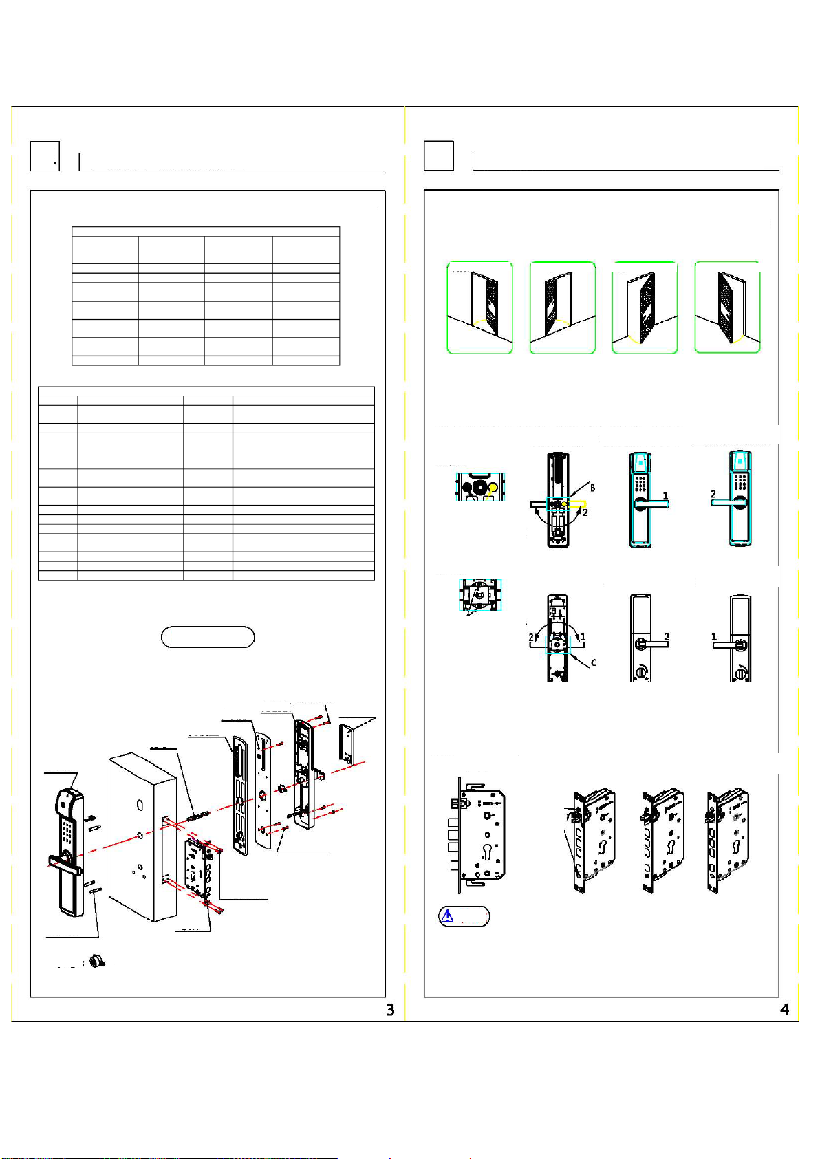
11、It is suggested to turn on the safety button when going out, which means to turn on the cat's
eye protection function. The opening state is shown in the following figure.
Normal
state
Open state
2.Unlock in double fingerprint mode
In this mode, you can unlock the door by any two previously registered fingerprints. The specific
steps are as follows: open the sliding cover or touch the screen to wake up the system, first
enter any fingerprint added before, and upon recognition, it will voice prompt "Please place the
second finger" to record another fingerprint. When the LED indicator light is green or the
warning tone of "Vehicle Sound" is given, press down the handle to open the door. When the
LED indicator light is green or the warning tone of "Vehicle Sound" is given, press down the
handle to open the door.
3. Fingerprint password mode unclocked
The specific steps are as follows: open the sliding cover or touch the screen to wake up the
system, first enter any fingerprint added before, and upon a “beep”, it will voice prompt “please
enter the password” to enter the valid password added, and then press [#] button to confirm; or
first enter the admin password, press [#] button to confirm, then it will voice prompt "Please
place the finger" to record any non-temporary fingerprint added before.
4.Unlock by mechanical key
If the password is forgotten, the fingerprint cannot be identified, the battery runs out or the
system cannot operate normally, etc., the mechanical key can be used for unlocking. Insert the
assigned mechanical key into the lock hole at the bottom of the front cover plate and rotate 90°,
then press down the handle to unlock the door (the mechanical keycannot open the oblique bolt
and the main bolt, and the key must not be forced for unlocking to avoid damage). It is
accompanied by a one-minute audible and visual alarm, which can be released by admin
fingerprint.
5.Unlock by card
This function is an optional function. If the password is forgotten, the fingerprint cannot be
identified, or the system is awakened, the door will be unlocked by swiping the added card on
the touch screen.
6.Door lock
For outdoor lock, the door can be locked only by lifting the external handle, and for indoor lock,
the door can be locked by lifting the internal handle. For indoor counter-lock, it can be locked by
rotating the counter-lock knob, in which case only the administrator fingerprint or password can
be used for unlocking.
Caution
1、Only by the administrator account can the management mode be entered for performing appeal
operations.
2、Some in the above operations are with voice prompts and the LED indicator light will make
corresponding judgment according to the results you set. During normal operations, the LED
indicator light will be blue, after any operation is completed, theLED indicator light will be green,
and after any operation fails, the LED indicator light will be red. In the mute mode, besides
judging the operating results through the LED indicator light, it can also be judged through the
prompt tone. "Vehicle tone" means the operation is completed and "beep" means the operation
has failed.
3、During normal use, when the battery is low, the system will give a low-voltage alarm and the
LED red light will flash and prompt "Please replace the battery when the battery is low."
4、For unlock by password, if entering the password incorrectly 5 times in a row, the system will be
locked for one minute, and an alarm will be given with the LED red light flashing.
5、The smart lock supports the functions of front virtual password and rear virtual password. As
long as the input unlocking password contains a complete and valid password combination, the
door can be unlocked, but the total number of digits of the input password cannot be greater
than 20.
6、For temporary passwords, temporary fingerprints and temporary cards, they will be
automatically deleted after unlocking once, with no time setting.
7、This smart lock does not allow repeated registration of saved passwords/fingerprints/card
accounts.
8、This smart lock is a green energy-saving product. After stopping operations for 12 seconds, the
system will return to the sleep energy-saving state and touch the button to wake up the system.
9、When the door lock is seriously deformed or broken by external force, the smart lock will send
out an audible and visual alarm signal, which can not only deter criminals but also give users
prompt in time.
10、The smart lock can match different networking modules as required to realize networking
functions.
Smart Lock Setup Guide
V
Safety precautions
VI
Guide on the Use of the Smart Lock
1.Unlock in the normal mode
In this mode, the user can unlock the door through any valid fingerprint orpassword registered before,
and the specific steps are as follows: open the sliding cover or touch the screen to wake up the
system and input any valid fingerprint or password registered. When the LED indicator light is green or
the warning tone of "Vehicle Sound" is given, press down the handle to open the door.
Waking up the
system
Password
entry
Fingerprint
entry
Press the
handle

Product Operating
Instruction
Building B, E-Link World Internet of Things
Industrial Park, Qingpu District, Shanghai
Main Technical Parameters
VII
1、Main technical parameters:
The main technical parameters of this smart lock are shown in the following
table:
No.
Category
Details
Technical features
1 Operating power
Operating voltage
4*1.5V AA Battery (5#)
Battery life
≈6000 times
Alarm voltage
≤4.8V
2 <font color="#000000">Power
consumption</font>
Quiescent current
≤70uA
Dynamic current
≤200mA
Peak current
≤300mA
3 Fingerprint collector
60
-30℃~60℃
Relative
temperature
20%-95%
Fingerprint capacity
199 pcs
Memory ability
100 years
False Reject Rate
<0.1%
False Accept Rate
<0.001%
Acquisition angle
360°
Fingerprint sensor
Semiconductor
fingerprint sensor
4 Password
Password length
6-12 digit
Password capacity
99 sets
5
Card
Card capacity
99 sets
6 Auxiliary function Clock function
Time and date
adjustment
Unlock record
Best 200 unlock
records
7 LED display
Screen area
0.96 inch
Display content
Operating process and
results
Operating
Temperature
-25℃~60℃
8 Zigbee smart module
Operating
Temperature
-25℃~55℃
Operating
Temperature
0~99RH
9 Executive standards
GA 701-2007 GA
21556-2008
Disclaimer
We have done our best to ensure that the information provided in this manual is
correct and reliable, however, we cannot fully guarantee that there will be no errors
before and during printing. Please understand that sometimes, in order to improve
the performance, reliability and installation convenience of components and
systems, we may upgrade the products, which may lead to some inconsistencies
between the actual products and the instructions, which however will not affect the
actual operations. The functions described in this manual shall not be used as a
reason for using this product for special purposes and the company shall not assume
any responsibilities for accident or harm caused by user's wrong operation.
Thank you for your careful reading of this manual. If you encounter any problems in
using this smart lock in the future, please contact your local dealer or our service
hotline in time.
SMS132K
2018.12
Super Smart Lock
Table of contents
Popular Door Lock manuals by other brands

Assa Abloy
Assa Abloy ANYKEY Operation instructions

Kwikset
Kwikset Smartcode 914 Programming and troubleshooting guide

Salto
Salto E1CD0x00fft installation guide

Karcher Design
Karcher Design EZ180 RCBR 71 Assembly instruction

schmersal
schmersal AZM 200 AS operating instructions

Pizzato Elettrica
Pizzato Elettrica P-KUBE 2 Safety