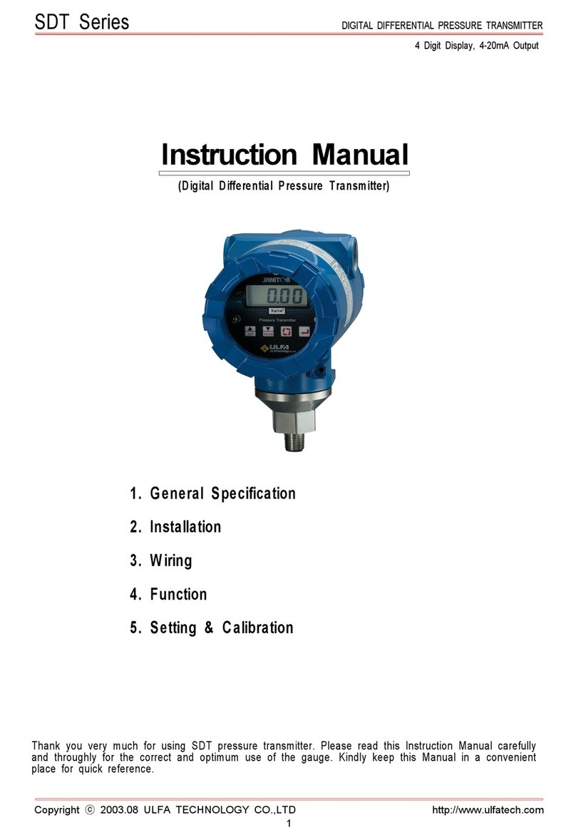
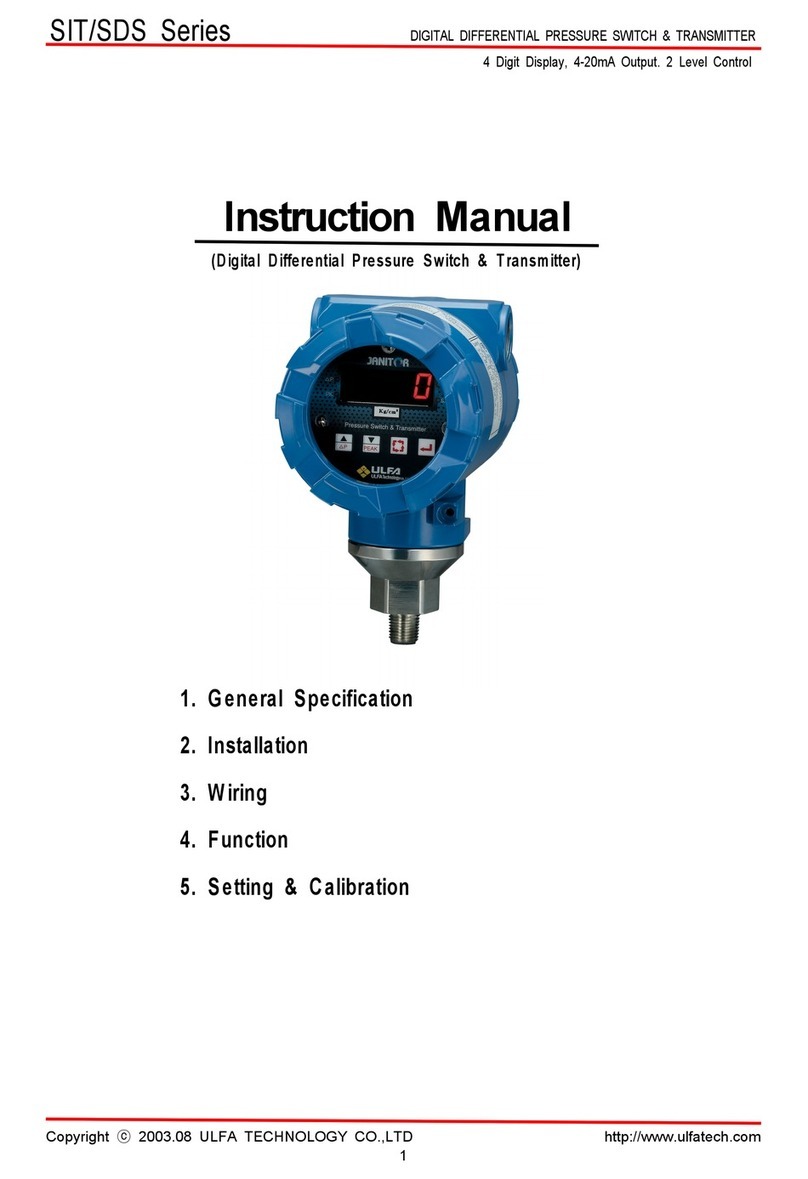
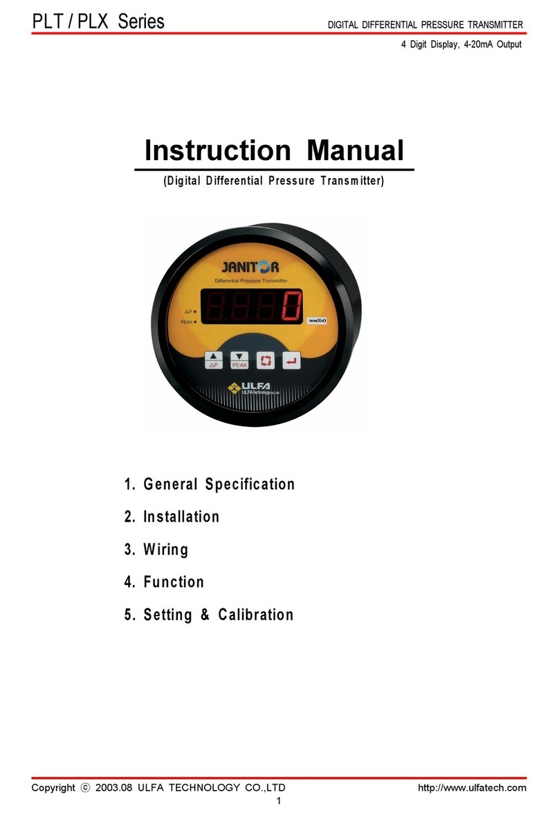
ULFA TECHNOLOGY JANITOR PDT Series User manual

PDT Series
DIGITAL DIFFERENTIAL PRESSURE TRANSMITTER
Copyright 2003.08 ULFA TECHNOLOGY CO.,LTD http://www.ulfatech.com
1
Instruction Manual
(D ig ita l D iffe re n tia l P re s su re T ra n s m itte r)
1. G e n era l S p ecific a tio n
2. In sta llatio n
3. W irin g
4. Func tio n
5. S etting & C alib ratio n
4 Digit Display, 4-20mA Output

PDT Series
DIGITAL DIFFERENTIAL PRESSURE TRANSMITTER
Copyright 2003.08 ULFA TECHNOLOGY CO.,LTD http://www.ulfatech.com
2
General Specification
PDT Series pressure transmitter are measures
and controls positive, negative(vacuum) and
differential pressure of air or non corrosive
gases, and for the variously choice of ranges
available to suit yourneeds precisely.
The PDT Widely used to measure fan and
blower pressures, filter resistance, pressure
drop across orifice plates, liquid levels in
storage tanks and many other applications. The
PDT model has four functions of gauge, peak
pressure detection, Offset( p) pressure and
transmitter. It is very easy to set and use by
front pad key.
Accuracy is +/-0.25% of full scale.
GENERAL
Maximum Pressure:
Rated Ran
g
e x 3
Media Compatibilit
y
:
A
ir and non corrosive
g
as
Pressure Ran
g
e:
Refer to ran
g
e table
ELECTRICAL
Power Suppl
y
:
DC24V
(
100-.220VAC
50~60Hz
)
Connections:
2 screw terminal block
Displa
y
:
4 Di
g
it LCD
Warm up Time:
15 minutes
TRANSMITTER
Connections:
2 Screw terminal block
Output Si
g
nal:
4-20mADC
(
limited at
30mADC
)
Loop Resistance:
0 - 1100
Zero & Span Ad
j
:
One touch Ad
j
ustable on
Panel
PERFORMANCE AT 23
Ran
g
e Table
Zero Output:
4 mA
Model No Range Resolution
Full Span Output:
20 mA
A
ccurac
y
:
±0.25 % FSO
(
Includes
Linearity, Hysteresis &
Repeatability)
-B15M ±15.0 mmH2O 0.1 mmH2O
-B150M ±150.0 mmH2O 0.1 mmH2O
Operating Temperature:
-10 to 70
-B1500M ±1500 mmH2O 1 mmH2O
-B760H ±760 mmHg 1 mmHg MECHANICAL
-D30M 0~30.0 mmH2O 0.1 mmH2O
Pressure Connections:
1/8" PT female
Materials:
ABS Mold Resin
-D300M 0~300.0 mmH2O 0.1 mmH2O
Weight
600g
-D3000M 0~3000 mmH2O 1 mmH2O
-B01K ±1.000 kg/cm20.001 kg/cm2
STANDARD ACCESSARIES
-B07K ±7.00 kg/cm20.01 kg/cm2
Tow
(
2
)
1/8" PT plu
g
s for duplicate/ Snap rin
g
Mounting ring, four(4) mounting screws
We can apply to other user specification
(Pressure units and range)
unit: mm
Differential Pressure Transmitter
Model :
Range :
Max Pressure :
S / N :
HIGH LOW
MADE IN KOREA
EXT.
18-35V
1
2
3
4
75
20
41
ULFA TECHNOLOGY CO.,LTD
100
92
5

PDT Series
DIGITAL DIFFERENTIAL PRESSURE TRANSMITTER
Copyright ⓒ 2003.08 ULFA TECHNOLOGY CO.,LTD http://www.ulfatech.com
3
Installation Wirin
g
LOCATION : Select your site location , Clean and
dry, no shock and vibration, proper to the ambien
t
temperature and humidity in use.
PANEL MOUNTING
The PDT Series Digital Pressure Transmitter is
designed for panel mounting in a single
93mm diameter hole.
POWER CONNECTION
The following procedures are to be used to install a
standard 24V DC main power source.
1. Before connection, the user must first confirm that
the power specification is DC24V or AC100-220V.
2. Verify that the facility's main power source is
turned off or disconnected.
3. Connect lead cable to power terminal matchin
g
polarity as shown in FIG.2 below. Take care that
wrong wiring will damage the Instrument and
malfunction (AC220V is not concerned to polarity)
CURRENT OUT CONNECTION(4-20mA)
The PDT sends a standard 2wire 4-20mA current out
1. Connect lead cable to current out terminal
matching polarity as shown in FIG.2 below.
2.
Do not run the signal cable along with any hi
g
h
voltage or power cable or put them in the same
race way. It may cause malfunction due to
induction.
A panel mounting fastening kit is provided with all
PDT Series Pressure Transmitter.
1. Select your site location, mark the appropriate
panel cutout and complete the necessary panel cut.
2. Carefully insert the Pressure Transmitter through the
hole from front of the panel.
3. Carefully insert the mount ring through the body o
f
PDT from back side.
4. Insert the snap ring to the snap ring groove.
5. Tightening four mount screw through the mount rin
g
from back side.
PRESSURE PORT CONNECTION
Tow(2) PT 1/8" barbed nipples are provided with all
PDT Series Pressure Transmitter
1. Wind teflon seal tape 3 or 4 times on the screw o
f
the nipple and tightening it in the pressure port
high and low
2. If you use the PDT to measure differential pressure,
high pressure is connect to 'HIGH" port, and low
pressure is connect to "LOW" port.
3. If you use PDT to measure single pressure,
positive pressure is connect to "HIGH" port and
negative pressure(vacuum) is connect to "LOW"
port. (In this case, another port is open to air)
4. Standard pressure connections are barbed fittin
g
s
for 3/16" I.D. tubin
g
.
2Wire4 Wire
4~20mA
mA
Receiver
SUPPLY
24VDC
POWER
1
2
3
4
0 5 40353025201510
Max Value
Supply Voltage(VDC)
ReceiverResistance(
)
50
700
800
900
600
500
400
300
200
100
20mADC
Vps-12.0
1200
1100
1000
1300
1400
FIG.1
The ranges of optimum receiver resistance is
refer to below graph.
FIG.2
SUPPLY
24VDC
POWER
PANEL
SCREW MOUNT RING
SNAP RING
93mm HOLE
SNAP RING GROOVE
1
2
3
4
mA
Receiver
4~20mA
JUMPER
R Max =

PDT Series
DIGITAL DIFFERENTIAL PRESSURE TRANSMITTER
Copyright ⓒ 2003.08 ULFA TECHNOLOGY CO.,LTD http://www.ulfatech.com
4
Function Settin
g
and Calibration
Zero setting : Optimize display and current out t
o
zero automatically by front key pressed.
Peak pressure Measurement : This mode i
s
display for peak pressure by supplied pressure. And
the display is cleared by press enter key in the pea
k
mode.
Offset(△p) pressure Measurement : Thi
s
mode is display the changed pressure based on th
e
current pressure. Current pressure is turned into "0"
when offset mode selected. This mode does no
t
concern to 4-20mA current out put.
Sampling time setting : Sample rate is 0.1se
c
of this product. Sampling time is measuring time b
y
sample rate. For example, if setting time is 2 sec,
PDT measures 20 times for 2 seconds and out t
o
display and 4-20mA out put by average of 20 time
s
measured value.
Transmitter : PDT has 4-20mA current out put.
Span (20mA) range can be changed within original
range.
Communication(option) : Measurement
pressure can be sent by RS232 or RS485 for option
specification.
ID setting : This mode set identification numbe
r
for communication.
Over pressure warning : PDT displays warning
on LCD for over pressure (positive and negative).
Upper 4elementsofsegment("— — — —")blinkfo
r
warning when measurement pressure over 10% fo
r
high pressure(factory setting value), And under
4
elements of segment("_ _ _ _") blink for warning
when measurement pressure under 10% for lo
w
pressure(factory setting value),
Factory setting recovery : The parameters ar
e
changed all to factory setting value and all use
r
setting value is cleared.
Hear by describe key function and setting methode.
Please read this section carefully for the correct and
optimum use of this product.
Ke
y
functions
UP
- Increase setting value
- Offset mode set/reset
DOWN
- Decrease setting value
- Peak pressure mode set/reset
MODE
- Entering into the setting mode
- Setting item circulation
ENTER
- Save setting value
- Clear peak value in the peak mode
- Release setting mode
Peak mode
Press the PEAK
(
down
)
key once to set peak
mode
"PEA" displayed like left
while press peak key
Press the ENTER to
reset peak value and
newly start
Press the PEAK
(
down
)
key once more to release
peak mode
Offset mode
Press the
△
P(UP) ke
y
once to set offset mode
"dELt" displayed like left
while press
△
P key
Press the
△
P(UP) ke
y
once more to release
offset mode
P
PEAK
P
PEAK
P
PEAK
P PEAK
PEAK
P
PEAK
P
PEAK
P
PEAK
P

PDT Series
DIGITAL DIFFERENTIAL PRESSURE TRANSMITTER
Copyright ⓒ 2003.08 ULFA TECHNOLOGY CO.,LTD http://www.ulfatech.com
5
User settin
g
mode Zero settin
g
Entering User setting mode : Pres
s
MODE key for more than 3seconds till appear "I n t"
on LCD into the user setting mode. Press th
e
MODE key once in user setting mode to chang
e
setting item. The setting item circulate " I n t "
⇒
" PoFS " ⇒ " P 4 " ⇒ " P20 " ⇒ " Id " ⇒ " FAC
t
" ⇒ " I n t " while mode key press repeated.
Each item setting methode is refer to next pages.
Save : If you complete your setting in the each
mode, Press ENTER once to save and exit t
o
measure mode.
Press ENTER for more than 3 seconds to save and
exist in the setting mode.
Release User setting mode :
Press ENTER once to save and exit to measur
e
mode.
If you are not operate this instrument for about 1
minute, It's released user setting mode automaticall
y
and return to measuring mode.
Optimize zero to display and current out automaticall
y
by front key pressed.
CAUTION : Release pressure port free before
zero set
Press MODE for more
than 3 seconds till
appear "Int" on LCD
display
Press MODE ke
y
once
till appear "PoFS" on
LCD display.
Press ENTER once to
set zero and exit to
measure mode. "PoFS"
blink for about 5 seconds
to calculate zero.
Press ENTER ke
y
for
more than 5 seconds till
appear "SAvE" on LCD
display to save and exist
in the setting mode.
Sampling time setting
It can be set 0.1~5.0 seconds by 0.1 sec resolution.
PDT reading pressure 0.1sec interval for a setting
time and calculate average pressure to display and
4-20mA output.
(ex) setting time : 2 sec
PDT reading pressure 20 times for 2 seconds
and calculate average of measured 20 data t
o
display and 4-20mA current output.
This functions is useful to measure hunted pressure
Press MODE key for
more than 3 seconds till
appear "Int" on LCD
display like left.
Release MODE ke
y
then
appear current set time
on LCD display
(
default
set time is 0.5 sec)
Set
y
our samplin
g
time
use up/down key
Press ENTER once to
save and exit to measure
mode.
Press ENTER key for
more than 3 seconds till
appear "SAvE" on display
to save and exist in the
sampling time settin
g
mode
4mA current settin
g
This function is set pressure level to 4mA current out.
Generally pressure zero is setting to 4mA current out.
By the way, negative pressure is setting in anothe
r
case. PDT can be set any pressure level to 4m
A
current out between low and high pressure range.
Low and high pressure ranges are setting in factory.
Press MODE key for
more than 3 seconds till
appear "Int" on LCD
display.
Press MODE ke
y
once
till appear "P4" on LCD
display.
Set
y
our pressure level
to 4mA out use up/down
key
Press ENTER once to
save and exit to measure
mode.
Press ENTER ke
y
for
more than 3 seconds till
appear "SAvE" on LCD
display to save and exist
in the setting mode
PEAK
P
PEAK
P
PEAK
P
PEAK
P
PEAK
P
PEAK
P
PEAK
P
PEAK
P
PEAK
P
PEAK
P
PEAK
P
PEAK
P
PEAK
P
PEAK
P
PEAK
P

Copyright 2003.08 ULFA TECHNOLOGY CO.,LTDhttp://www.ulfatech.com
6
PEAK
P
PEAK
P
PEAK
P
PEAK
P
PEAK
P
PEAK
P
PEAK
P
PEAK
P
PEAK
P
20mA current settin
g
value
This function is set pressure level to 20mA curren
t
out,That isset span. PDT can be set an
y
pressure level to 20mA current out between lo
w
and high pressure ranges.
Low and high pressure ranges are setting in factory.
Recall to Factor
y
settin
g
This function is recall to initial states of factory
out from unmatched user parameters that zero,
span etc.
PressMODE ke
y
for
more than 3 seconds till
appear "Int"on LCD
display.
Press MODE ke
y
once
till appear "P20" on
LCD display.
Set
y
our pressure level
to 20mA current out use
up/down key
Press ENTER once to
save and exit to measure
mode.
Press ENTER ke
y
for
more than 3 seconds till
appear "SAvE"onLCD
tosaveandexist in the
settingmode
Press MODE ke
y
for
more than 3 seconds till
appear "Int"on LCD
display.
Press MODE ke
y
once
till appear "FACt" on
LCD display.
Press ENTER once to
recall and exit to measure
mode.
Press ENTER ke
y
for
more than 3 seconds till
appear "SAvE"onLCD
to recalland existin the
settingmode
ID No settin
g
ID number is use for address for communication t
o
master.It's concern to PDT communication functio
n
installed.(option)
Press MODE key for
more than 3 seconds till
appear "Int"on LCD
display.
PressMODE ke
y
once
tillappear "ID"on
segment.
Set
y
our IDNo use
up/downkey(0~255)
default set is0.
Press ENTER once to
save and exittomeasure
mode.
Press ENTERke
y
for
morethan 3 seconds till
appear "SAvE"onLCD
tosaveandexist in the
settingmode.
ULFA TECHNOLOGY CO.,LTD
344, industrial zone ,201 haan 3-dong
kwang myung-city, kyung ki-do
423-754 KOREA
TEL:02-806-4403 FAX:02-806-4406
PDT Series
DIGITAL DIFFERENTIAL PRESSURE TRANSMITTER
PEAK
P
PEAK
P
PEAK
P
PEAK
P
PEAK
P
Table of contents
Other ULFA TECHNOLOGY Transmitter manuals