ULTRA LEGS Tri-Toon User manual

www.ultralegs.com
1
Ultra Legs®Tri-Toon
Installation Guide
3006.4611
Ultra Legs®are a hydraulic leg lift that attaches to your pontoon, giving you the freedom and
range to take your lift anywhere you can take your pontoon. The Twin-Tube model operates
with two sets of legs, each set is strengthened by a reinforced crossbar and holds a sturdy
footpad. The Tri-Toon model comes complete with four separate legs. When not in operation,
the legs nestle within inches of the deck of your pontoon, invisible to the unknowing eye, yet
when operating, Ultra Legs®gives your boat up to six feet of lift, keeping it safe, secure and out
of the water in nearly any shallow water situation. Rocks, muck, wind and current are no match
for your new lift. Welcome to Ultra Legs®.
CAUTION:
Installation of Ultra Legs®should be done only by trained and authorized professionals, needs
a minimum of two people and requires access to the underside of the pontoon receiving the
Ultra Legs®. Under no circumstances should installation be attempted in water as severe injury,
drowning or death may occur. Install only in a well-lit area on a hard, flat surface. Ultra Legs®
require at minimum six feet above and in front of your pontoon to check product operation
during installation. Always wear appropriate protective equipment.
Do not begin installation until these requirements have been met.
Equipment Checklist:
Included in your Ultra Legs®package should be the following:
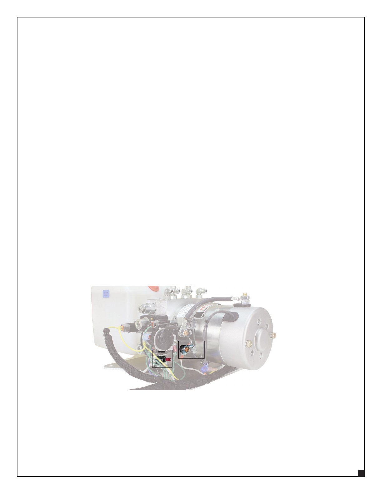
• Ultra Legs®Power Unit and Remote Control (1): 2.5 HP, 12VDC, uni-rotational electric motor for
raising and retracting lifting leg cylinders.
• Ultra Legs®Leg Component (4): Leg Components with 3500 psi and solid steel Hydraulic
Cylinder construction.
• Ultra Legs®Oil
o 2.5 Gallon Bottle (1): Used for initial installation.
o 1 Gallon Bottle (1): Used for initial installation.
• Ultra Legs®Installation Kit
o 360” Hydraulic Hose (1)
o 252” Hydraulic Hose (2): Purple, Purple/Brown
o 192” Hydraulic Hose (3): Orange, White, Orange/White
o 96” Hydraulic Hose (2)
o 28.5” Hydraulic Hose (2)
o 12” Hydraulic Whip Hose (4)
o 15’ Battery Cables (2): Red, Black
o 5/16” x 1” Zinc-plated Hex Lag Screw (4)
o 5/16 – 18 x 1” Hex Cap Bolts (56)
o 5/16 – 18 Flange Lock Nut (56)
o #8 x 1” Stainless Steel Screws (9)
o Cable Tie with Eye (5)
o Cable Tie without Eye (10)
o T-Fitting (2)
o 90° Fitting (8)

www.ultralegs.com
2
Recommended Tools:
• Drill with 5/16” and 1/8” standard steel bits, 5/16” and 1/8” 8”-10” long steel bits and 2” hole saw bit
• 1/2” Ratchet with extensions and sockets
• Open end wrenches: 1/2”, 9/16”, 7/16”, 15mm, 17mm
• Impact wrench
• C-clamps or large vise-grips (4)
• Tape measures (2)
• 1/4” socket or hex driver
• Wire & Cable Cutter
• Hex Lug & Terminal Crimper
Battery Requirements:
• Use a fully charged Starting Battery with a minimum 850 cold cranking amps, such as a
Group 27 battery.
Ultra Legs®Floor Jack:
Ultra Legs®offers a floor jack specifically designed to make installation of Ultra Legs®easier.
Contact Ultra Legs®for more information.
INSTALLATION
Set-Up:
• Place pontoon securely onto blocks on a flat, clean and dry surface with adequate clearance
above and in front of boat. Area should be free of obstructions. A minimum of two people
should be used in the installation of Ultra Legs®. Blocks should raise the pontoon 24” off the
ground at minimum.
Power Unit and Hoses:
1. Locate the corner-seat compartment on the deck of the pontoon; this is generally the best
location for the Power Unit. Should the corner seat compartment be too small or unavailable,
other under-seat compartments may work as well, though adjustments to cable placements
may be needed.
Note: Power Unit must not be placed in the same compartment as the pontoon battery.
2. Set the Power Unit into the chosen compartment in a position not contacting the walls of the
compartment to ensure proper fit. Mark this position.
3. Find a spot near the Power Unit large enough for a 2” hole for the hydraulic hoses. Mark this
location. Remove the Power Unit from the compartment.
4. Drill a 1/8” pilot hole at the marked location through the compartment floor and pontoon
deck being careful not to hit any wiring or puncture a pontoon. Once the pilot hole has been
established as free from wiring and safe, drill a 2” hole over the original pilot hole through
the compartment floor and pontoon deck.
5. Find the location each hydraulic hose will be placed and mark these locations.
a. Rear Leg Components: Measure 52” forward from the rear-most full crossbar in each
tunnel. Mark that location on the nearest crossbar. This location is to where rear-
running hoses will be routed.
b. Front Leg Components: Measure 42” back from the front-most full crossbar in each
tunnel. Mark that location on the nearest crossbar. This location is to where forward-
running hoses will be routed.

www.ultralegs.com
3
6. Feed the provided hydraulic hoses through the compartment hole and into the pontoon
support brackets leaving enough length inside the compartment to allow hookup to the
Power Unit.
a. Route the 360” hose over the middle pontoon to the marked location on the driver-
side bow.
b. Run the two 252” hoses (Purple, Purple/Brown) toward the marked location on the
passenger-side bow.
c. Place the three 192” hoses (Orange, White, Orange/White) toward the stern of the
boat. Route the White hose over the middle pontoon to driver-side stern.
7. Feed the battery cables (Black, Red) through the same hole and route them toward the
battery compartment. For adjacent battery compartments, battery cables may be run
through a hole in the wall as opposed to underneath the boat.
8. In the Power Unit compartment, place and fasten the Remote Receiver vertically to a wall
with the provided stainless steel screws, avoiding close proximity to any speakers to avoid
frequency interference.
9. Replace the Power Unit back into its original marked position and fasten it to the floor with
the provided lag screws.
10. Connect and secure the hose ends remaining in the compartment to the appropriate hose
fittings on the Power Unit.
a. DRE: Driver Rear Extend – White
b. PRE: Passenger Rear Extend – Orange
c. RR: Rear Retract – Orange/White
d. DFE: Driver Front Extend
e. PFE: Passenger Front Extend – Purple
f. FR: Front Retract – Purple/Brown
11. Cut battery wires to length, making the shortest direct connection possible. Crimp new
ends on using supplied terminals.
12. Connect the battery wire ends remaining in the compartment to the appropriate terminals
on the Power Unit as shown. Snug all bolts. Do not connect the wires to the battery.
13. Find the WeatherPack connectors on both the Power Unit and the Remote Receiver and
connect them to each other.
14. From underneath the boat, route the two 96” hydraulic hoses over the center pontoon, one
in the bow and one at the stern. While extended, each end should span the gap between
the marked locations at their respective ends of the boat.
15. Secure all hoses and wires both in the compartment and underneath the boat neatly using
cable ties. Power Unit installation is now complete.
+

www.ultralegs.com
4
HYDRAULIC HOSE CONNECTION
Driver-Side Stern:
1. Fasten the 96” hydraulic hose to the 90° fitting on the cylinder’s rod-end.
2. Connect the 192” White hydraulic hose to the 12” whip hose.
3. Secure the 96” hydraulic hose toward the piston-end of the cylinder to maintain clearance
from the unit’s pinch points.
4. Make sure all connections have been tightened.
Passenger-Side Stern
1. Fasten a 28.5” hydraulic hose to the 90° fitting on the cylinder’s rod-end.
2. Connect a T-Fitting to the free end of the 28.5” hydraulic hose.
3. Connect the 96” hydraulic hose to an end of the T-Fitting.
4. Secure the 192” Orange/White hydraulic hose to the free end of the T-Fitting.
5. Fasten the 192” Orange hydraulic hose to the 12” whip hose.
6. Secure the 28.5” hydraulic hose toward the piston-end of the cylinder to maintain clearance
from the unit’s pinch points.
7. Make sure all connections have been tightened.
Driver-Side Bow
1. Fasten the 96” hydraulic hose to the 90° fitting on the cylinder’s rod-end.
2. Connect the 360” hydraulic hose to the 12” whip hose.
3. Secure the 96” hydraulic hose toward the piston-end of the cylinder to maintain clearance
from the unit’s pinch points.
4. Make sure all connections have been tightened.
Passenger-Side Bow
1. Fasten a 28.5” hydraulic hose to the 90° fitting on the cylinder’s rod-end.
2. Connect a T-Fitting to the free end of the 28.5” hydraulic hose.
3. Connect the 96” hydraulic hose to an end of the T-Fitting.
4. Secure the 252” Purple/Brown hydraulic hose to the free end of the T-Fitting.
5. Fasten the 252” Purple hydraulic hose to the 12” whip hose.
6. Secure the 28.5” hydraulic hose toward the piston-end of the cylinder to maintain clearance
from the unit’s pinch points.
7. Make sure all connections have been tightened.

www.ultralegs.com
5
FILLING HYDRAULIC SYSTEM
Never run Ultra Legs®without oil in the oil tank. Filling the hydraulic system takes time and
must be done slowly to ensure all air is removed from the system. Air remaining in the system
may prevent smooth operation. Ultra Legs®require approximately thirteen quarts of oil. While
filling the hydraulic system, you will be raising and lowering the pontoon; make sure adequate
space is had before initiating fill. Use only Ultra Legs®provided oil.
1. Connect black battery wire to the Negative ( – ) battery terminal and the red battery wire to
the Positive ( + ) battery terminal. Ensure all hoses have been tightened.
2. Using the 2.5 gallon bottle and the 1 gallon bottle, slowly pour oil into the oil tank until it is
1/2” from the top.
3. Press the ALL button on the remote control. Do not let the oil level drop below half
full. As the level drops, add more oil to maintain a safe oil level. Continue this until the alarm
sounds to signal that the legs have been fully retracted.
4. Fill oil level to within 1” of top of the tank.
5. Press the ALL button on the remote control to raise the pontoon fully into the standing
position. Do this slowly and do not let the oil level drop below half full. As the level drops,
add more oil to maintain a safe oil level.
6. Press the ALL button on the remote control to lower the pontoon back onto the blocks.
Do this slowly and do not let the oil level drop below half full. As the level drops, add more
oil to maintain a safe oil level.
7. Press the FRONT button on the remote control. Do not let the oil level drop below
half full. As the level drops, add more oil to maintain a safe oil level. Lift until the bow of the
pontoon begins to lift off the blocks.
8. Check for leaks in all front hoses and fittings.
9. Press the REAR button on the remote control. Do not let the oil level drop below half
full. As the level drops, add more oil to maintain a safe oil level. Lift until the stern of the
pontoon begins to lift off the blocks.
10. Check for leaks in all rear hoses and fittings.
11. Ensure blocks are still in place, then press the ALL button on the remote control.
Continue this until the alarm sounds to signal that the legs have been fully retracted.
12. Press the ALL button on the remote control. Do not let the oil level drop below half
full. As the level drops, add more oil to maintain a safe oil level at slightly above half full.
Continue this until the pontoon reaches its full height. You may have to toggle the bow or
stern individually during lifting to levelly raise the pontoon.
13. At this point, the oil level in the tank should be approximately half full as oil will return to
the tank as the boat lowers. Only add more oil if the oil level drops below half full, and only
fill back to half full.

www.ultralegs.com
6
14. Ensure the blocks are still in place, then press the ALL button on the remote control.
Continue this until the alarm sounds to signal that the legs have been fully retracted.
15. Cycle the pontoon all the way up and down twice more, going slowly or pausing
periodically to allow any trapped air to release from the system. Fill oil tank as necessary.
16. The Ultra Legs®hydraulic system is now full.
Final Steps:
1. Lift the pontoon into the full upright position.
2. Walking underneath, find and secure any loose wiring or hoses with cable ties.
3. Step out from underneath the boat and lower it onto the blocks until the alarm sounds.
4. Fill oil tank to within 1” of top, then secure the oil tank cap in place.
Program Remote:
Ultra Leg remote receivers allow for the programming of up to three (3) remote control units.
To program a new remote control or to reset the original remote control if the remote receiver
no longer recognizes it, follow the following instructions.
1. Locate the remote receiver in the compartment next to the hydraulic pump.
2. Disconnect the harness from between the pump and receiver.
3. Reconnect the harness between the pump and receiver. The receiver will now be in “Pairing
Mode” for 10 seconds.
4. Press and hold ON button on the remote for three (3) seconds during the pairing window.
5. The remote should now function properly.
Remote Troubleshooting:
• Each remote is equipped with a 10-minute standby timer. After 10 minutes of no commands
being sent, the remote will go into standby mode. To resume operation, press the ON button
to wake the remote and resume control. Toggle switches will remain operational on the
receiver box even if the remote is in standby mode.
• The receiver can hold up to three (3) remote pairings. Pairing a new remote after all three
pairings are filled will cycle and remove the oldest stored remote to add the newest pairing.
• If the pairing process is not able to be completed per the instructions, ensure the pump is
connected to a fully charged battery and that any battery switches are in the “on” position.

www.ultralegs.com
7
TRI-TOON
Part No. 3006.8029
360” Hose
Brown
Port
Starboard
Part No. 3006.8032
12” Hose
Part No. 3006.8032
12” Hose
Part No. 3006.7966
252” Hose
Purple
Part No. 3006.8026
252” Hose
Brown/Purple
Part No. 3006.8035
102” Hose
Part No. 3006.8035
102” Hose
Part No. 3006.7969
90° Fitting
Part No. 3006.7969
90° Fitting
Part No. 3006.7969
Part No. 3006.8017
192” Hose
Orange
Part No. 3006.8032
12” Hose
Part No.3006.7948
28.5” Hose
Part No. 3006.8032
12” Hose
Part No. 3006.8020
192” Hose
White
Part No. 3006.7969
90° Fitting
Part No. 3006.7969
90° Fitting
Part No. 3006.7975
T-Fitting
Part No. 3006.8023
192” Hose
Orange/White
Part No. 3006.7975
T-Fitting
Part No. 3006.7948
28.5” Hose
94”
8”
28”
70”
7”
Side View Open
This manual suits for next models
1
Table of contents